Chapter 7
Installation of General Circuits and Equipment
ARTICLE 100 DEFINITIONS*
*References in the margins are to the specific applicable rules and tables in the National Electrical Code.
This chapter deals with the installation of conductors and equipment for general use in electrical systems. Such equipment is normally used to conduct or control electricity or to perform some mechanical function rather than utilize electrical energy for useful purposes. The items considered include cabinets, conduit bodies, cutout boxes, devices, fittings, raceways, and switches. Distribution equipment and utilization equipment are covered in later chapters of the Guide.
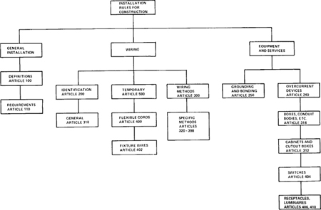
For convenience, the Code rules for general installation can be separated as shown in Figure 7–1 into general rules, wiring rules, and rules for equipment and devices. These rules apply to all installations unless modified by other rules dealing with specific circuits, equipment, or occupancies.
Figure 7–1. Organization of Code Rules for the Installation of Conductors and Equipment for General Use
The chapter divides the discussion of installation rules as follows: (a) use of conductors in circuits, (b) installation and protection of conductors, (c) wiring methods, (d) equipment grounding and bonding, and (e) equipment and devices. In each section summary tables and discussions concentrate on the basic installation rules. Information of primary concern to manufacturers is not covered except as it aids in understanding the intent of the Code. In many cases, an abbreviated discussion, or no mention at all, is given of certain Code rules that are considered less general than the ones covered but may nevertheless be of interest in a specific situation. The reader, therefore, is urged to study the Code text completely even though the Guide covers only a portion of the material presented there.
7–1 Use of Conductors in Circuits
ARTICLE 240
When current-carrying conductors are used in an electrical system, the Code requires that each conductor be protected from damage by an overcurrent protective device such as a circuit breaker or fuse. The conductors must also be identified so that the ungrounded conductors may be distinguished from the grounded and grounding conductors. Minimum sizes or required ampacity for any of these conductors used in a circuit are selected based on Code rules and tables. The Code also provides tables that list the physical and electrical properties of conductors to allow the designer to select the proper conductor for any application.
7–1.1 Overcurrent Protection of Conductors
240.4
Table 7–1 summarizes the Code rules for protecting conductors from excess current caused by overloads, short circuits, or ground faults. The setting or sizes of the protective device are based on the ampacity of the conductors as listed in appropriate Code tables. Under certain conditions, the overcurrent device setting may be larger than the ampacity rating of the conductors as listed in the exceptions to the basic rule. For convenience, a standard rating of a fuse or circuit breaker may be used even if this rating exceeds the ampacity of the conductor if the rating does not exceed 800 amperes.
Table 7–1. Overcurrent Protection of Conductors
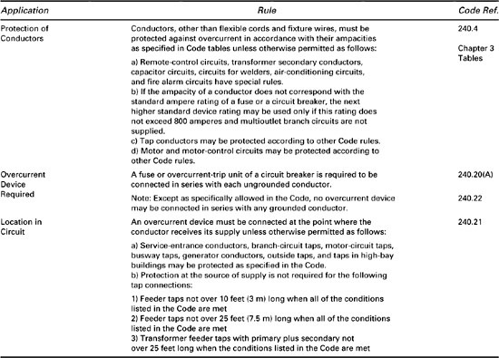
240.21
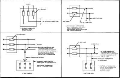
In most cases, an overcurrent device must be connected at the point where the conductor to be protected receives its supply as shown in Figure 7–2(a). Figure 7–2(b) illustrates tap conductors protected with overcurrent protection matching their ampacity. Figures 7–2(c) and 7–2(d) illustrate the 10-foot tap rule and the 25-foot tap rule, respectively.
Figure 7–2. Overcurrent Protection of Conductors
7–1.2 Identification of Conductors
200.2
Premises wiring systems require a grounded conductor in most installations. A grounded conductor, such as the neutral, or a grounding conductor must be identified either by the color of its insulation, by markings at the terminals, or by other suitable means. Table 7–2 summarizes the rules for identification of both grounded and grounding conductors.
Table 7–2. Identification of Conductors
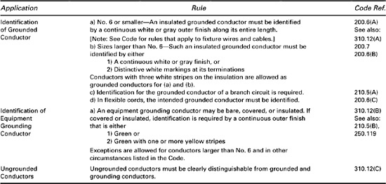
200.6, 310.12
Unless allowed by other means in the Code, a grounded conductor must have a white or gray finish. When this is not practical for conductors larger than No. 6, marking the terminals with white color is an acceptable method of identifying the conductor.
A grounding conductor, unless it is bare, must be identified by a green outer finish or a finish that is green with yellow stripes. Ungrounded conductors must be distinguishable from grounded conductors and must not use white, gray, or green colors or markings.
7–1.3 Size and Ampacity of Conductors
310.5
The minimum size conductors allowed for general wiring are No. 14 copper or No. 12 aluminum or copperclad aluminum. Smaller conductors are allowed in special circumstances as listed in Table 7–3. In most cases, however, conductors are selected based on the required ampacity to supply a given load rather than to meet the minimum size requirement.
Table 7–3. Size and Ampacity of Conductors
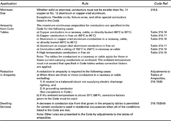
310.15
TABLE 310.16
The maximum continuous ampacity of copper, aluminum, and copperclad aluminum conductors are specified in Code tables that relate the AWG size to the ampacity of the conductor. In addition to specifying the ampacity of a given size conductor, separate Code tables are provided for enclosed conductors and for conductors exposed in air. The tables for “Not More Than Three Current-Carrying Conductors in Raceway or Cable” are normally used in design problems to determine the proper conductor size.
TABLES 310.18, 310.19
TABLE 310.18
If high-temperature (150°C to 250°C) conductors are used, separate tables of ampacities must be referenced to determine the allowable ampacity. For example, a No. 14, type THW, 75°C conductor is rated to carry 20 amperes in a raceway. The same size conductor with fluorinated ethylene propylene (FEP) insulation may carry 36 amperes continuously.
310.15(B)
Adjustments to the tables of ampacities modify the stated ampacities of conductors in certain installations. When more than three conductors are installed in a raceway or cable, the listed ampacities must be reduced because of the heating effect of many current-carrying conductors in proximity. Grounding conductors and neutral conductors are not counted as current-carrying conductors except when electric discharge lighting is served, in which case the neutral is counted.
The ampacity stated in the tables must also be reduced if the ambient temperature for the conductor location exceeds 30°C (86°F). This reduction is required even if the reduction for more than three conductors in a raceway is also applied. Thus, if six No. 10 type TW conductors carry current in a raceway where the ambient temperature is 40°C, the ampacity of 30 amperes must be reduced to 80% because of conduit fill and then reduced again by a correction factor of .82 because of the ambient. The allowable ampacity is then only .8 × .82 = .656 or 65.6% of the original value. The ampacity for six No. 10 type TW conductors in a 40°C ambient becomes
30 A × .8 × .82 = 19.68 A
310.15(B)
310.60
In the case of residential feeders or services consisting of a 120/240-volt, three-wire, single-phase circuit, the ampacity listed in the Code tables may be increased for certain types of conductors. In practice, the local enforcing agency determines whether or not this increase in ampacity is allowed and in some cases prohibits it. For installations where raceway or cables are buried in earth, specific Code tables must be used to determine conductor ampacity according to appropriate conditions. If the circuits operate at over 2000 volts, appropriate Code tables of ampacities must be used.
7–1.4 Properties of Conductors
Various Code tables listed in Table 7–4 define the physical and electrical properties of conductors. Electrical designers use the Code tables of physical properties to select the type of conductors and the size of conduit required to enclose the conductors in a specific application.
Table 7–4. Tables of Properties for Conductors
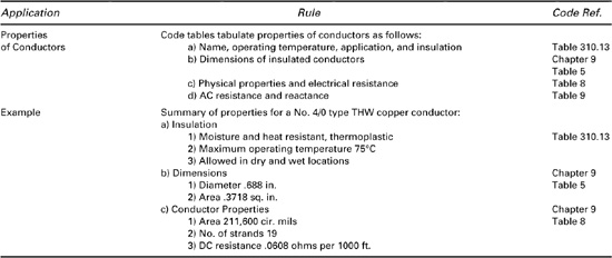
CHAPTER 9
TABLE 8, TABLE 9
In other design problems the dc resistance and wire area are used to solve problems involving voltage drop. When large conductors are used in ac circuits, the inductive reactance increases the effective impedance and hence the voltage drop for a given length of wire. Table 7–4 also summarizes the properties of a No. 4/0 type THW copper conductor as an example and to show how these properties are used.
7–1.5 Miscellaneous Types of Conductors
ARTICLE 400, ARTICLE 402
Flexible cords and cables and fixture wires are subject to special rules presented in the Code. The use of these conductors in circuits is restricted to the connections listed by the Code.
7–2 Installation and Protection of Conductors
Conductors must be installed and protected from damage according to rules set forth in the Code. Additional rules specify the use of boxes or fittings for certain connections, specify how connections are made to terminals, and restrict the use of parallel conductors. When conductors are installed in enclosures or raceways, additional rules apply. Finally, if conductors are installed underground, the burial depth and other installation requirements are specified by the Code.
This section covers the rules that determine the method of installation and protection of conductors under various conditions. If the conductors form a specific circuit, such as a branch circuit, feeder, or service, additional rules may apply as discussed in Chapter 6 of the Guide.
7–2.1 General Rules for Conductor Installation
110.11
310.8
Table 7–5 lists the general rules that govern the installation of conductors. Insulated conductors that are identified for use in the intended location must be used as required by the Code. In wet locations, for example, only certain types of conductors specified in the Code such as type RHW may be used since the insulation of these conductors is able to resist water damage (as indicated by the letter W in the type designation).
Table 7–5. General Rules for Installation of Conductors
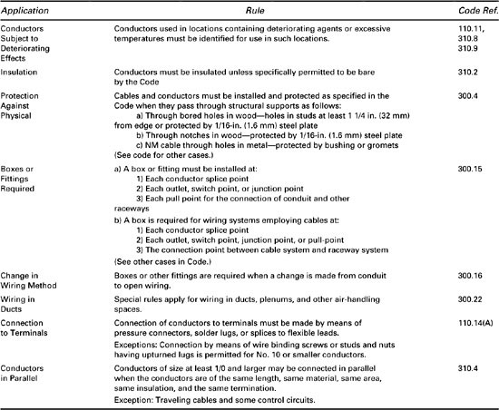
300.4
Cables and conductors must also be adequately protected from physical damage and must have special protection when they pass through bored holes, notches in wood, or holes in metal frames. A steel plate at least ![]() inch (1.6 mm) in thickness must be installed to protect cables likely to be damaged from nails or screws that might accidently penetrate the cable.
inch (1.6 mm) in thickness must be installed to protect cables likely to be damaged from nails or screws that might accidently penetrate the cable.
Whenever conductors are spliced, connected, or pulled, a box or fitting must be installed for the connection of conduit and other raceways. If a cable system is to be connected to a raceway system, a box is required at the point of connection.
110.14(A)
Connection of conductors to terminals must be made with pressure connectors, solder lugs, or splices if the conductors are larger than No. 10. Conductors of size No. 10 or smaller may be connected by wire binding screws or studs and nuts.
310.4
Conductors of size 1/0 and larger run in parallel must all have the same construction and electrical properties. Smaller size conductors are not permitted to be run in parallel in power circuits.
7–2.2 Conductors in Enclosures and Raceways
In many installations, conductors are routed in a raceway system for convenience and to provide physical protection. The circuits are connected in splice boxes and terminate at outlets or other enclosures such as panelboards. In such installations, the various Code rules listed in Table 7–6 apply.
Table 7–6. Instllation of Conductors in Enclosures and Raceways
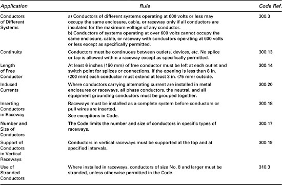
300.3
Conductors of systems operating at different voltages up to 600 volts may occupy the same enclosure, cable, or raceway where all conductors are insulated for the maximum voltage.
300.13
300.14
When conductors are installed, they must be mechanically and electrically continuous between outlets, devices, etc.; splices are not permitted within a raceway itself except for wiring methods that specifically permit such splices. At each outlet or switch point where splices are permitted or fixtures are to be connected there must be at least 6 inches of conductor left free for the connection.
300.18
300.17
310.3
Unless a raceway is exposed with a hinged or removable cover, a raceway system must be installed as a complete system without conductors. Pull wires may then be installed and the conductors pulled in as long as the number or size of conductors does not exceed that which allows dissipation of heat and safe installation or withdrawal of the conductors. The Code specifies the number and size of conductors that may be used with a particular type of raceway of a given size. General conductors of size No. 8 or larger must be stranded when installed in raceways.
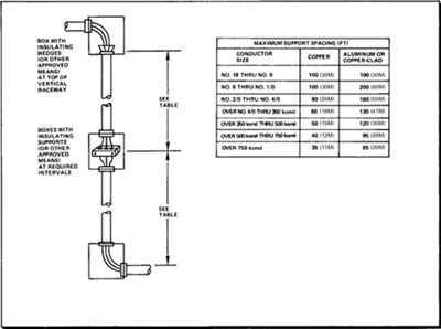
300.19
As shown in Figure 7–3, conductors in vertical raceways must be supported at the top and at fixed intervals. An approved method using clamps or other support is required.
Figure 7–3. Support of Conductors in Vertical Raceway
7–2.3 Underground Installations
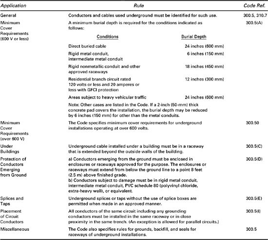
310.8, 300.5
Conductors and cables installed underground must be listed for such use and be protected from physical damage. The rules for underground installations and the minimum burial depths are listed in Table 7–7.
Table 7–7. Rules for Underground Installations
7–3 Wiring Methods and Techniques
110.8
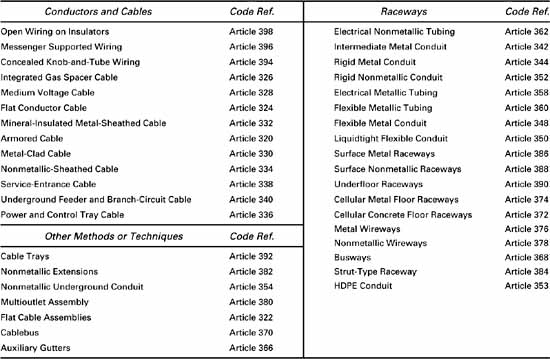
The Code recognizes various wiring methods that may be properly installed in buildings or other occupancies. Table 7–8 lists the specific methods and techniques covered in the Code. For convenience, the wiring methods are separated into those using cables and conductors, those using raceways, and those using other methods. Selected wiring methods are discussed in this section of the Guide and summary tables are presented indicating the description, use, and installation rules for the more common methods.
Table 7–8. Summary of Wiring Methods and Techniques
7–3.1 Wiring Methods Using Conductors and Cables
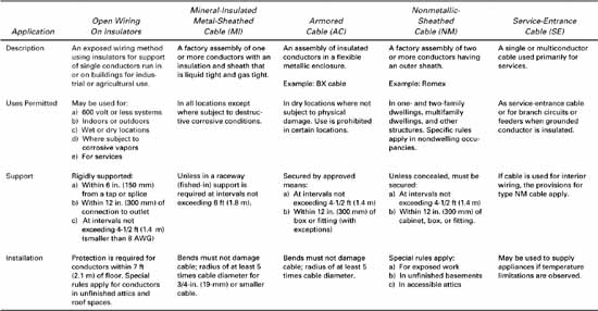
In addition to the general rules for the installation of cables and conductors, specific wiring methods are treated in separate Code articles. Table 7–9 presents a brief summary of the Code rules for a few selected wiring methods in common use.
Table 7–9. Installation Rules for Selected Wiring Methods Using Cables or Conductors
7–3.2 Wiring Methods Using Raceways
In industrial and commercial construction, raceways are used to contain conductors and cables for electrical distribution to panelboards, switchboards, and outlets. Each type of raceway is approved for certain uses with installation rules given in the Code that apply to each type. The most common raceways are of the conduit type consisting of circular metallic or nonmetallic tubes that enclose the conductors. Other types of raceways have very specific uses as outlined in the Code.
ARTICLE 344
Conduit-Type Raceways. Table 7–10 summarizes the rules for raceways that normally come in standard lengths of circular tubing. The basic raceway is rigid metal conduit that provides maximum protection for conductors in any installation. Because of its high cost and because it is difficult to install, other types of similar raceways have been developed that are less expensive, lighter in weight, and easier to install.
Table 7–10. Rules for Installation of Conduit-Type Raceways

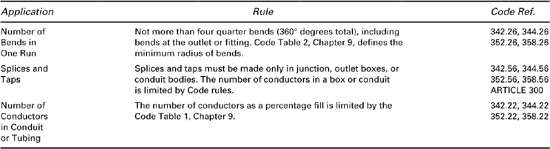
The similar rules of installation for intermediate metal conduit, rigid metal conduit, rigid nonmetallic conduit, and electrical metallic tubing are summarized in Table 7–11. The rules for flexible conduit differ significantly from those of the other types and are not included in the table.
Table 7–11. Rules for the Installation of Conduits and Tubing (Except Flexible Types)
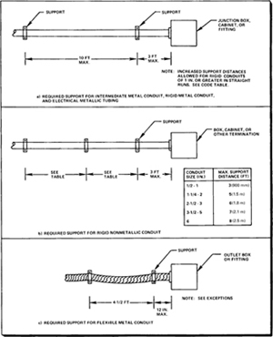
Every raceway must be supported at fixed intervals as specified in the Code. Figure 7–4 illustrates the support distances for the raceways listed in Table 7–10.
Figure 7–4. Required Support for Conduit-Type Raceways
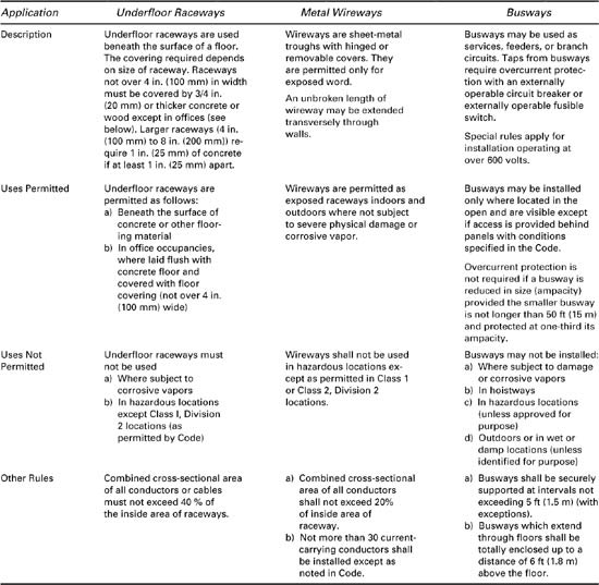
Other Raceways. In addition to conduit-type raceways, several other wiring methods using raceways are permitted by the Code. The rules for underfloor raceways, wireways, and busways are summarized in Table 7–12 to describe only three of the approved methods.
Table 7–12. Installation Rules for Underfloor Raceways, Wireways, and Busways
ARTICLE 390
The underfloor raceway system consists of ducts connected by special junction boxes. Floor outlets are easily attached by using special inserts set or screwed into the walls of the ducts. The raceways must be laid in straight lines and must be held firmly in place. When an outlet is removed, the circuit wiring must also be removed from the raceway.
ARTICLE 376
Wireways are installed exposed to allow access to conductors or cables at all points for tapping, splicing, etc., without disturbing existing wiring. Metal wireways must be supported at least every 5 feet (1.5 m) unless listed for greater distances between supports or run vertically.
ARTICLE 368
Busways are used primarily to provide a flexible distribution system within a building (although approved outdoor types are available). A common use is in machine shops to supply power for power tools or machines that may be moved occasionally. A plug-in overcurrent device with an externally operable circuit breaker or switch is used to tap a branch circuit, with a power cord serving as the branch-circuit conductors from the plug-in unit to the outlet for the machine.
7–3.3 Other Wiring Methods and Techniques
ARTICLE 366
To meet particular installation requirements, the Code allows a number of special wiring methods and techniques in addition to the common methods previously discussed. A typical example of such special techniques is the use of auxiliary gutters. An auxiliary gutter is used to supplement wiring spaces at meter centers and similar locations. The gutters are sheet-metal troughs in which conductors may be routed after the gutter has been installed. In multifamily dwellings, for example, auxiliary gutters are used to enclose the wiring, including splices and taps, for individual metering of apartments. Slightly different rules apply to nonmetallic auxiliary gutters.
The auxiliary gutter may extend not more than 30 feet beyond the equipment that it supplements (except for elevators). The trough may not contain more than 30 current-carrying conductors and may not be filled to more than 20% of the interior cross-sectional area (with certain exceptions). When splices or taps are made, the total area of conductors, including splices and taps, must not exceed 75% of the area of the gutter.
7–4 Equipment Grounding and Bonding
ARTICLE 250
The grounding and bonding of the noncurrent-carrying metal parts of equipment is treated extensively in the Code. Grounding is required for most equipment unless excepted or specifically prohibited in the Code. Bonding is normally only required to assure electrical continuity when the continuity may be broken by connections, loose joints, or the like.
7–4.1 Equipment Grounding
250.3
250.112, 250.114
Table 7–13 summarizes the equipment grounding rules for any type of equipment that is required to be grounded. These general Code rules apply to all installations unless amended by other Code rules for specific equipment. The Code provides a reference list of additional rules that modify or extend the basic rules for grounding equipment. The Code also lists specific equipment that is to be grounded regardless of voltage.
Table 7–13. Equipment Grounding Rules
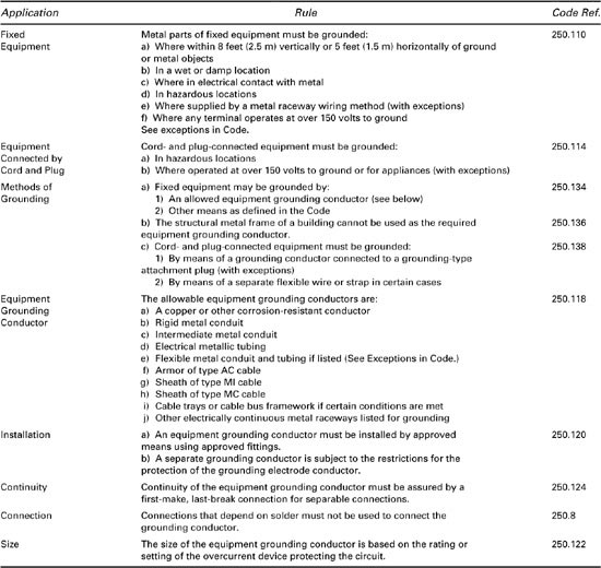
In all occupancies, major appliances and many motor-operated tools are required to be grounded. The appliances include refrigerators, freezers, air conditioners, clothes washing and drying machines, dishwashing machines, sump pumps, and electrical aquarium equipment. Other tools likely to be used outdoors and in wet or damp locations must be grounded or have a system of double insulation.
250.140, 250.142
Although new appliance circuits require an equipment grounding conductor, the frames of electric ranges and clothes dryers may be grounded by the grounded circuit conductor for existing circuits. This is allowed if the supply circuit is 120/240 volts or 120/208 volts, single-phase and if the grounded conductor is of size No. 10 or larger and is insulated (with exceptions). Also, the grounding contacts of receptacles on the equipment must be bonded to the equipment. If these specified conditions are met, it is not necessary to provide a separate equipment grounding conductor, either for the frames or any outlet or junction boxes which are part of the circuit for these appliances.
7–4.2 Equipment Bonding
ARTICLE 100 DEFINITIONS
A bonding jumper is sometimes used to assure electrical conductivity between metal parts. When the jumper is installed to connect two or more portions of the equipment grounding conductor, the jumper is referred to as an equipment bonding jumper. The rules for the equipment bonding jumper are summarized in Table 7–14. Some specific cases in which a bonding jumper is required are also listed in the table.
Table 7–14. Installation Rules for Equipment Bonding Jumper
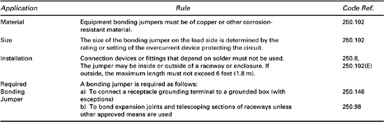
250.96
250.118
Metal raceways, cable armor, and other metal noncurrent-carrying parts that serve as grounding conductors must be bonded whenever necessary in order to assure electrical continuity. When flexible metal conduit that is not listed for grounding is used for equipment grounding, an equipment bonding jumper is required if the length of the ground return path exceeds 6 feet (1.8 m) or the circuit enclosed is rated over 20 amperes. When the path exceeds 6 feet (1.8 m), the circuit must contain an equipment grounding conductor and the bonding may be accomplished by approved fittings.
250.102
A short length of flexible metal conduit that contains a circuit rated greater than 20 amperes may not serve as a grounding conductor itself, but a separate bonding jumper can be provided in lieu of a separate equipment grounding conductor for the circuit. This bonding jumper may be installed inside or outside the conduit, but an outside jumper cannot exceed 6 feet (1.8 m) in length.
250.97
In many instances, a bonding jumper is not required to bond equipment together to assure electrical continuity. For raceways, cable armor, etc., suitable fittings or threaded couplings may serve to bond sections together. If a circuit operates at over 250 volts to ground, the methods used for bonding service equipment can be used or threadless fittings made up tight may serve to bond conduit or metalclad cable. For threaded metal conduit, a connection to a box or cabinet can use two locknuts, one inside and one outside, to bond the conduit or cable to the box.
7–5 Equipment and Devices
This section discusses Code rules for the installation of various types of electrical equipment and devices that are used to construct a complete electrical system. The purpose of these items is to conduct or control electricity or to perform a mechanical function in the electrical system. Figure 7–5 illustrates this type of equipment, which includes fuses, device boxes, conduit bodies, and pull boxes. Other devices that are used in systems include overcurrent devices, switches, receptacles, and certain types of lighting fixtures and associated apparatus.
Figure 7–5. Miscellaneous Electrical Devices
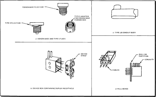
Various boxes are used as junction boxes for splices or as device boxes to support switches and outlets. Small boxes come in standard sizes, and restrictions are placed on the number of conductors or devices they may contain. Larger boxes and conduit bodies are used as junction boxes and pull boxes for installations using conduit or other raceway methods.
Cabinets and cutout boxes normally enclose apparatus that must be accessible through a door or panel that can be opened easily. Circuit breakers and control equipment are placed in such enclosures.
7–5.1 Overcurrent Devices
ARTICLE 240
This section deals with the installation of circuit breakers and fuses used for overcurrent protection of conductors. Table 7–15 summarizes the rules for these devices and the other rules that apply to all types of overcurrent devices. When fuses serve as the overcurrent protective device, the Code specifically considers plug fuses and cartridge fuses.
Table 7–15. Installation Rules for Overcurrent Devices
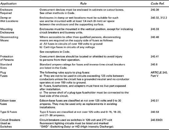
ARTICLE 240, PART V
Plug fuses have a screw-shell base and are commonly used in dwellings for circuits that supply lighting, heating, and appliances. Plug fuses are supplied with standard screw bases (Edison-base) or type S bases. Edison-base fuses are permitted only as replacements in existing installations. These fuses are being replaced with type S fuses that are constructed so that a larger ampere rated fuse will not fit the fuse holder or adapter for a lower rated size. In most industrial and commercial applications, cartridge fuses are used because they have a wider range of types, sizes, and ratings than do plug fuses.
7–5.2 Boxes Containing Outlets, Receptacles, Switches, or Devices
Boxes are used to contain conductors as well as outlets, receptacles, switches, fittings, and devices. They differ from cabinets and cutout boxes in that the covers are normally screwed or bolted on rather than hinged for easy access. The most common smaller boxes are used for light fixtures, switches, and receptacles. Larger boxes of 100-cubic inch capacity or more are normally used as junction boxes or pull boxes as described in the next section of the Guide.
TABLE 314.16(A)
In addition to the general installation rules listed in Table 7–16, the Code restricts the number of conductors allowed in a standard box of a given size. For a 4-inch by 1½-inch square box, for instance, ten No. 14 conductors may be enclosed or four No. 6 conductors.
Table 7–16. Installation Rules for Boxes Containing Outlets, Receptacles, Etc.
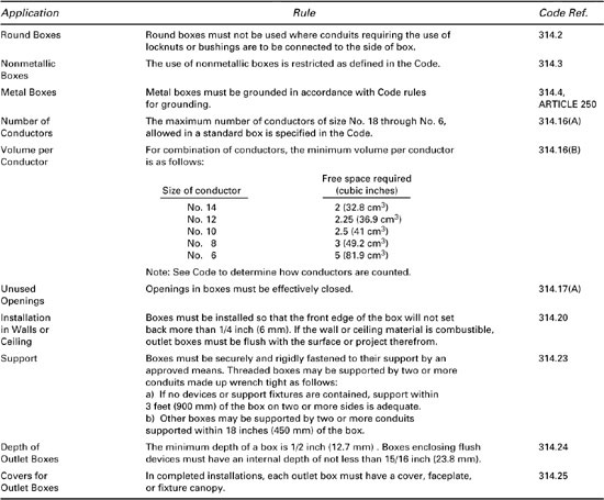
TABLE 314.16(B)
The opposite problem, that of determining the size of box needed to enclose a given number of conductors, is solved by calculating the total volume of conductors based on a Code table of volume required per conductor. In addition to the actual circuit conductors, other devices or conductors in the box are counted as follows:
a. Fixture studs, cable clamps, or hickeys count as one conductor each
b. Each mounting yoke or strap counts as two conductors (for switches or receptacles)
c. One or more grounding conductors count as only one conductor
d. A conductor running through the box is counted as one conductor
e. Each conductor originating outside the box and terminating within the box is counted as one conductor
By adding up the number of conductors and their volumes, the proper size box may be selected. The volume required per conductor is listed in Table 7–16.
If a box contains a duplex receptacle supplied by two No. 14, two-wire cables (plus one grounding conductor per cable), the number of conductors to be counted is:
![]()
Each No. 14 conductor requires 2 cubic inches. Thus, a device box of over 14 cubic inches is required. A standard 3-inch by 2-inch by 234-inch device box would be adequate.
7–5.3 Conduit Bodies, Pull Boxes, and Junction Boxes
300.15
ARTICLE 100 DEFINITIONS
At each splice point, junction point, or pull point for the connection of conduit or other raceways, a box or fitting must be installed. The Code specifically considers conduit bodies, pull boxes, and junction boxes and specifies the installation rules as listed in Table 7–17.
Table 7–17. Installation Rules for Conduit Bodies, Pull and Junction Boxes
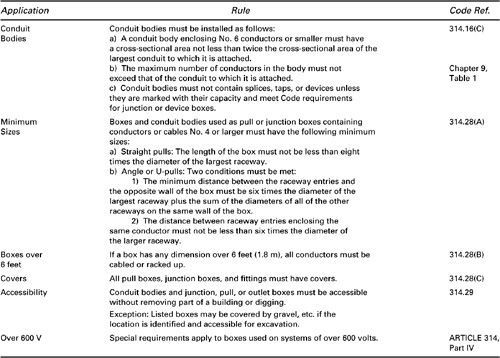
314.16(C)
Conduit bodies provide access to the wiring through removable covers. Typical examples are type T, type E, and type LB. Conduit bodies enclosing No. 6 or smaller conductors must have an area twice that of the largest conduit to which they are attached, but the number of conductors within the body must not exceed that allowed in the conduit. If a conduit body is marked with its cubic inch capacity, splices may be made within the conduit body. Splices may not be made in conduit bodies unless the volume is indicated. Conduit bodies must be supported.
314.28
When conduit bodies or boxes are used as junction boxes or as pull boxes, a minimum size box is required to allow conductors to be installed without undue bending. The calculated dimensions of the box depend on the type of conduit arrangement and on the size of the conduits involved.
For straight pulls or junctions in straight runs of conduit, the length of the box must be at least eight times the trade diameter of the largest conduit. If the conductors are smaller than No. 4, the length restriction does not apply. Figure 7–6(a) shows the minimum length for a box connected to one 3-inch conduit and two 2-inch conduits all containing No. 1/0 conductors. The minimum length is 8 × 3 inches = 24 inches.
Figure 7–6. Minimum Size Pull Boxes
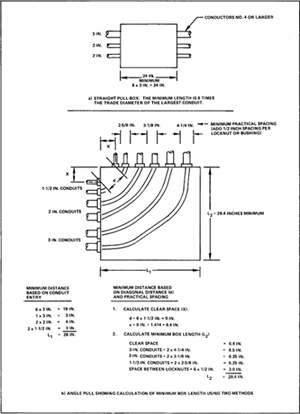
In angle or U-pulls, two conditions must be met in order to determine the length and width of the required box. First, the minimum distance to the opposite side of the box from any conduit entry must be at least six times the trade diameter of the largest raceway plus the sum of the diameters of the raceways on the same wall. Figure 7–6(b) shows the minimum length of a box with two 3-inch conduits, two 2-inch conduits, and two 1½-inch conduits in a right-angle pull. The minimum length based on this configuration is:
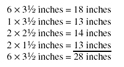
Since the number and size of conduits on the two sides of the box are equal, the box is square and has a minimum side dimension of 28 inches. This size box is not sufficient, however, because it does not meet the complete Code requirements.
The second condition given in the Code must also be checked to assure that the box is large enough. In addition to the minimum length for the box, the spacing between raceways enclosing the same conductor must not be less than six times the raceway diameter. Figure 7–6(b) shows that the diagonal spacing must be
![]()
The distance from the corner of the box to the center of the conduits (x) is then the diagonal distance (d) divided by the square root of 2 (1.414). For the 1½-inch conduits, this distance is 9 inches ÷ 1.414 = 6.4 inches. In order to determine the required length, this distance must be added to the spacing of the other conduits, including locknuts or bushings and clearance for a wrench. As shown in Figure 7–6(b), the minimum length calculated this way is 29.4 inches; therefore, this larger length must be used. The spacing for the conduits was based on a measurement of the locknuts with ½-inch clearance between locknuts.
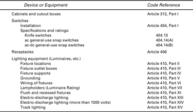
7–5.4 Cabinets and Cutout Boxes, Switches, Receptacles, and Luminaires
The Code provides rules for miscellaneous devices and equipment such as cabinets and cutout boxes, switches, receptacles, luminaires (lighting fixtures), and similar devices. Although many of the rules deal with the manufacture or construction of the units, a summary of the important references for installation is listed below.