Chapter 6
Installation Rules For Specific Circuits or Systems
This chapter presents a discussion of the Code rules for the installation of electrical wiring considered as a complete circuit or system. Branch circuits, feeders, services, systems operating at over 600 volts, and miscellaneous circuits and systems are discussed. These particular circuits and systems are covered separately by the Code and the requirements for them supplement or modify Code rules that apply to any installation.
The installation rules in this chapter apply to the circuits or systems discussed regardless of the type of equipment supplied except as specifically noted. Additional rules apply when specific loads such as appliances or motors are supplied.
In addition to the installation rules presented in this chapter, the Code specifies a number of rules concerned with the design of circuits to supply various loads. These rules are discussed in Part I of the Guide and are not repeated here.
6–1 Installation of Branch Circuits
When a circuit is installed as a branch circuit, various Code rules must be followed to assure a safe installation in complete conformance with the Code. These branch-circuit installation rules can be separated into (a) general installation rules for any construction; (b) rules that apply only for dwellings; and (c) rules that apply for other specific locations, such as hotels or motels.
210.2*
*References in the margins are to the specific applicable rules and tables in the National Electrical Code.
This section discusses the installation of branch circuits in such locations. Other chapters in the Guide cover the additional requirements for branch circuits that supply particular loads including motors, electric space-heating equipment, and other utilization equipment. In fact, the Code includes a detailed list of other articles which contain rules for specific-purpose branch circuits.
6–1.1 General Installation Rules for Branch Circuits
ARTICLE 100 DEFINITIONS
Branch circuits in dwellings, commercial occupancies, and industrial areas are distinguished by their use. A general-purpose branch circuit supplies two or more outlets for lighting and appliances. An individual branch circuit can supply only a single unit that utilizes electrical energy. Restrictions are placed on the maximum rating and use of general-purpose branch circuits as explained in this section. Either type of branch circuit may be installed as a multiwire branch circuit, but a general-purpose multiwire branch circuit must conform to Code rules not applicable to individual branch circuits.
The grounded and the grounding conductors for any branch circuit that requires such conductors must be identified by color or other means to distinguish them from ungrounded conductors. Other Code rules that apply to every branch circuit specify the maximum voltage allowed under certain conditions and also specify rules that apply to receptacle outlets installed in branch circuits.
590.6
To protect personnel at a construction site, there must be ground-fault circuit interrupters on certain circuits. In some cases, a program of maintenance and testing for grounding conductors is allowed.
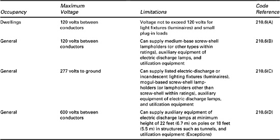
General rules for the installation of branch circuits are listed in Table 6–1 and a summary of the voltage limitations is presented in Table 6–2. The discussion that follows explains some of the more important rules although not every item in the tables is covered in the text.
Table 6–1. General Branch-Circuit Installation Rules
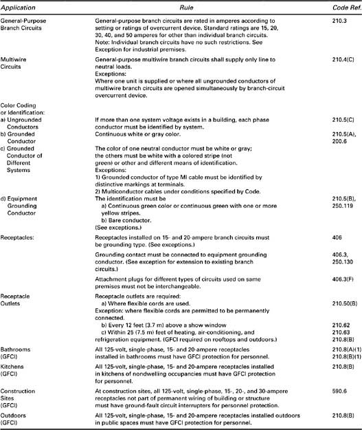
Table 6–2. Voltage Limitations for Branch Circuits
210.3
General-Purpose Branch Circuits. General-purpose branch circuits are classified according to the rating or setting of the overcurrent protective device for the circuit. When several outlets are supplied, the branch-circuit rating must be either 15, 20, 30, 40, or 50 amperes. If a load requires a supply current of more than 50 amperes, an individual branch circuit is required except in an industrial establishment.
210.4
A general-purpose multiwire branch circuit may supply only line-to-neutral loads except when all ungrounded conductors of the circuit are opened simultaneously by the branch-circuit protective device. For example, a 120/240-volt, three-wire circuit with grounded neutral may normally be used to supply only 120-volt loads, but it can supply combinations of 120- and 240-volt loads if all the ungrounded circuit conductors are opened simultaneously, for example, by a multiple-pole circuit breaker protecting the circuit.
Where more than one system voltage exists in a building, each ungrounded conductor must be identified by system at the branch-circuit panelboard. Each phase conductor can be identified by color coding, tagging, or other means.
210.5(A),
200.6
Color Coding of Grounded Conductors. The grounded conductor in a two-wire circuit or the neutral in a three-wire or four-wire circuit must, in most cases, be identified by a white or gray color. In certain cases, the identification can be at the terminals rather than continuously along the conductor. The grounded conductors of Type MI cable and grounded conductors of multiconductor cable maintained by qualified persons may be identified in that manner. If several circuits are installed in the same raceway or enclosure, one system neutral must be white or gray and the other neutrals must be identified by other means.
210.5(B),
205.119
Unless it is bare, the grounding conductor is required to be identified by a continuous green color or green with yellow stripes. The Code allows exceptions for insulated conductors larger than No. 6 or for an insulated conductor in a multiconductor cable maintained by qualified persons. In these cases, identification is required only where the conductor is accessible.
210.6(A)
210.6(D)
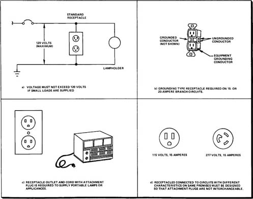
Maximum Voltage. As shown in Figure 6–1(a), the voltage for a branch circuit supplying lighting fixtures or small appliances (1440 VA or less) in dwellings must not exceed 120 volts. The conditions listed in Table 6–2 permit industrial and commercial lighting fixtures to be supplied by branch circuits with a voltage to ground of up to 277 volts when all specified conditions are met. This allows the use of the common 277-volt lighting system. Lighting on poles and in tunnels may operate at up to 600 volts between conductors if the height restrictions listed in Table 6–2 are met.
Figure 6–1. Illustrations of Branch-Circuit Rules for Any Type of Construction
ARTICLE 406
250.130
406.3
Receptacles. Receptacles installed on 15- or 20-ampere branch circuits must be of the grounding type and must have their grounding contact connected to the equipment grounding conductor of the circuit as shown in Figure 6–1(b). In existing installations in which an equipment grounding conductor is not present, the grounding contact may be connected to another point on the grounding system. If no grounding means exists, a nongrounding type receptacle or a ground-fault circuit interrupter (GFCI) receptacle must be used.
210.50(B)
400.7(B)
A receptacle outlet is required to supply equipment using a flexible supply cord except when flexible supply cords are specifically permitted to be permanently connected. When the receptacle is required, the cord must be equipped with an attachment plug, as shown in Figure 6–1(c), where portable lamps or appliances that must be moved occasionally are supplied.
210.62
Show windows require at least one-receptacle to be installed for each 12 feet of length. The receptacles must be installed directly above the window.
210.63
210.8(B)
210.70
A receptacle is required within 25 feet (7.5 m) of heating, air-conditioning, and refrigeration equipment. The required 15- or 20-ampere receptacle is intended to power electric hand tools or handlamps used during the servicing of the equipment. Similar equipment on a roof of a commercial building or a multifamily dwelling also requires an outlet for service purposes. Outdoor or rooftop receptacles and receptacles in the kitchen in nondwelling occupancies must also have ground-fault circuit-interrupter protection. A lighting outlet controlled by a switch is required at the entry to attics or underfloor spaces containing the equipment in any occupancy.
406.3(F)
If several circuits with different characteristics (voltage, current, frequency, etc.) are present on the same premises, the receptacle for each circuit must prevent the use of interchangeable attachment plugs. Figure 6–1(d) shows two standard receptacles for different voltages that meet this requirement.
590.6
Ground-Fault Circuit Interrupters for Construction Sites. GFCIs are required at construction sites for 120-volt, single-phase, 15-, 20-, and 30-ampere outlets that are not part of the permanent wiring system. Ground-fault circuit protection may not be required for certain circuits when an approved procedure is enforced to assure that equipment grounding conductors are properly installed and maintained. This Code exception requires a designated individual at the construction site to test the grounding system, as specified in the Code, including all equipment connected by cord and plug if ground-fault circuit interrupters are not provided.
6–1.2 Branch-Circuit Installation Rules for Dwelling Units
Specific consideration is given to branch-circuit installations in dwellings since the safety of the public is involved. Since misuse of electrical equipment in homes has caused many unfortunate accidents, Code rules assure that an adequate number of circuits and outlets is provided to avoid overloaded circuits and the excessive use of extension cords.
To provide the safety required in a dwelling, the maximum voltage between conductors for certain branch circuits is limited to 120 volts. Additional protection for the occupants is provided by ground-fault circuit interrupters on circuits in areas where the shock hazard is considered greatest.
The Code specifies the location and placement of receptacle outlets and lighting outlets in great detail. A sufficient number of outlets placed conveniently in a dwelling unit is required to yield an installation that meets Code rules for such occupancies.
Table 6–3 lists the pertinent installation rules for circuits and outlets in a dwelling.
Table 6–3. Branch-Circuit Installation Rules for Dwellings
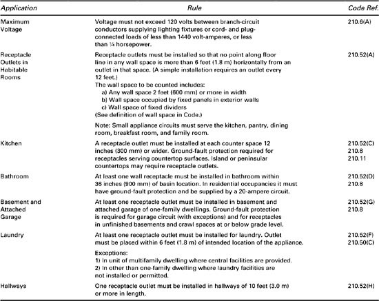
Maximum Voltage. On any branch circuit that supplies lighting fixtures or small appliances in dwelling units, the maximum voltage between conductors must not exceed 120 volts. Permanently connected appliances or large appliances rated 1440 watts or more connected by cord and plug may be supplied by a circuit with a higher voltage.
210.52(A)
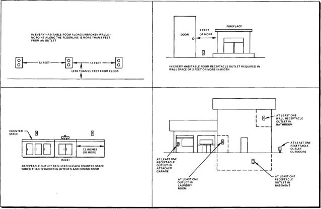
Receptacle Outlets Required. As illustrated in Figure 6–2, receptacle outlets are required in habitable rooms and kitchens so that no point along the floor line is more than 6 feet (1.8 m) from an outlet. On an unbroken wall, then, an outlet would be required at least every 12 feet. When a wall is broken by doorways, fireplaces, or similar openings, each wall space of 2 feet (600 mm) or more must be considered separately. The required receptacle outlets do not include those that are part of a lighting fixture or appliance or that are located in cabinets or cupboards. Also, those located over 5½ (1.7 m) feet above the floor or located in the floor away from the wall more than 18 inches do not count as required receptacles.
Figure 6–2. Placement of Receptacle Outlets in a Dwelling Unit
210.52(C)
210.52(c) 210.8
In the kitchen and dining areas a receptacle outlet must be installed at each countertop space 12 inches (300 mm) or wider. Receptacles must be installed in a kitchen so that no point along the wall line of a counter placed against a wall is more than 24 inches (600 mm) horizontally from a receptacle outlet. Island or peninsular countertops that are 24 (600 mm) or more inches in length and 12 or more inches (300 mm) in width require at least one receptacle outlet to be installed. Receptacle outlets must be located not more than 20 inches (500 mm) above the countertop. The countertop space separated by range tops, refrigerators, or sinks must be considered separately. These kitchen and dining area receptacle outlets must be supplied by two or more of the required 20-ampere small appliance branch circuits. Receptacles supplying countertop surfaces in the kitchen and within 6 feet (1.8 m) of a wet bar sink require GFCI protection.
210.52(D)
210.52(F)
210.50(c)
210.11(c)
Additionally, at least one wall receptacle outlet must be installed in the bathroom within 36 inches (900 mm) of the basin and at least one receptacle outlet must be installed for the laundry in every dwelling unit where laundry facilities are permitted. A laundry outlet is not required in individual dwelling units of multifamily dwellings if central facilities are provided or if individual laundry facilities are not permitted. When required, the receptacle outlet(s) for the laundry equipment must be placed within 6 feet (1.8 m) of the intended location of the appliance and the laundry receptacle outlet(s) must be supplied by a separate 20-ampere branch circuit.
210.52(E)
210.52(G)
210.8(A)
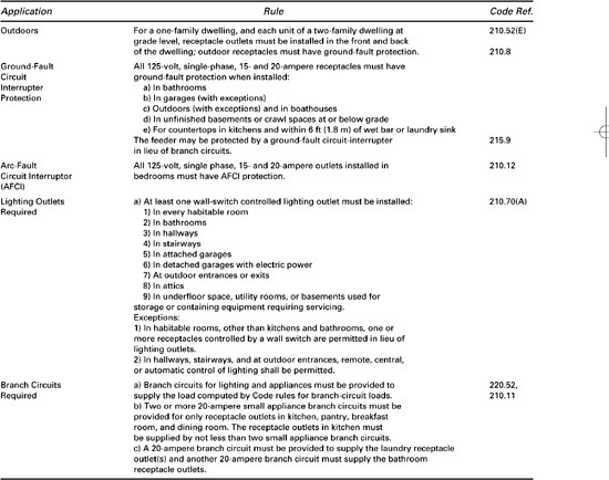
In one-family dwellings other receptacle outlets are required in the basement, in each attached garage, and outdoors. One-family dwellings and each unit of a two-family dwelling at grade level require a receptacle outlet outdoors at the front and at the back of the dwelling. Receptacle outlets in the garage (with exceptions) and outdoors (if the receptacles are general-purpose and readily accessible) must have ground-fault circuit-interrupter protection. Receptacles installed in an unfinished basement or in crawl spaces at or below grade level must have GFCI protection.
210.52(H)
210.63
In dwelling units, hallways of 10 feet (3.0 m) or longer require a receptacle outlet in the hallway. This receptacle could be used conveniently to power a vacuum cleaner or a hall lamp in an entrance hallway. A receptacle outlet is required within 25 feet (7.5 m) of heating or air-conditioning equipment.
210.8
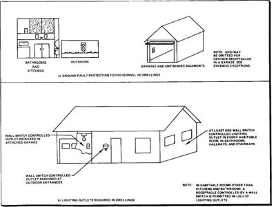
215.9
Ground-Fault Circuit Protection. As shown in Figure 6–3(a), certain receptacle outlets in dwelling units must have ground-fault circuit protection for personnel. This protection may be provided by a ground-fault circuit interrupter built into the receptacle itself or by a ground-fault circuit interrupter as part of either the branch-circuit circuit breaker or the circuit breaker protecting the feeder or service conductors. The principle of operation of the GFCI is based on the device’s sensing a difference in current between the ungrounded conductor and the neutral caused by a current flow to ground through a person’s body in contact with the ungrounded conductor. The GFCI opens the circuit when the detected difference exceeds a preset value. GFCI devices to protect occupants are usually set to operate at approximately 5 milliamperes since tests have determined that a current flow through a person’s body in excess of that value may be harmful.
Figure 6–3. Rules for Ground-Fault Protection and Required Lighting Outlets
210.12
The code requires an arc-fault circuit interrupter (AFCI) for all 125-volt, single-phase, 15-and 20-ampere outlets installed in dwelling unit bedrooms. The AFCI device is intended to provide protection from the effects of arc faults by deenergizing the circuit when an arc is detected. The arc is usually caused by a break in a current-carrying conductor or a fault without sufficient current to cause the branch-circuit overcurrent device to operate and protect the circuit.
210.70(A)
Lighting Outlets Required. In a dwelling as shown in Figure 6–3(b), wall-switch controlled lighting outlets are required in each habitable room, the bathroom, hallways, stairways, attached garages, and at outdoor entrances. A wall-switch controlled receptacle may be used in place of the lighting outlet in habitable rooms other than kitchens and bathrooms. Providing a wall switch for room lighting is intended to prevent an occupant’s groping in the dark for table lamps or pull chains. In certain locations, such as hallways, stairways, and outdoor entrances, the Code permits central or remote control of lighting.
Wall-switch controlled lighting outlets or a lighting outlet containing a switch are required in attics, underfloor space, utility rooms, and basements when these spaces are used for storage or contain equipment requiring servicing.
210.11
Branch Circuits Required. Branch circuits must be provided to supply the computed lighting load and appliance loads. In addition, two 20-ampere small appliance branch circuits and 20-ampere laundry and bathroom circuits must be provided in dwelling units.
6–1.3 Branch-Circuit Installation Rules for Guest Rooms or Guest Suites in Hotels and Motels
ARTICLE 100 DEFINITIONS
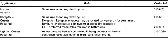
Table 6–4 summarizes the branch-circuit installation rules that apply to guest rooms of hotels and motels. These occupancies are not considered dwelling units if provisions for housekeeping, including eating, are not made available. Nevertheless, most rules for dwelling units apply to guest rooms, although receptacle outlets may be located where convenient for permanently installed furniture layouts.
Table 6–4. Branch Circuit Installation Rules for Guest Rooms
6–2 Installation Rules For Feeders
ARTICLE 215
ARTICLE 225
110.15
215.9
215.10
The Code provides specific installation requirements for feeders, but these requirements are not as extensive as those for branch circuits or services as shown by the summary in Table 6–5. A four-wire delta connected feeder, such as a high-leg delta circuit, must have the higher voltage phase identified when the midpoint of one phase is grounded. Also, the Code permits ground-fault circuit interrupter protection to be provided at the feeder rather than the branch circuit when GFCI is required. Certain feeder circuits require ground-fault protection of equipment as described in Section 6–3.2 of this Guide.
Table 6–5. Installation Rules for Feeders
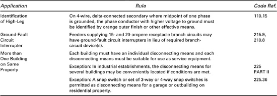
225, PART II
When more than one building is on the same property and under single management, the Code requires that each building be supplied by one feeder (with exceptions) and that a disconnecting means be provided for each building served. This disconnecting means must be suitable for use as service equipment unless the second building is a garage or similar structure on residential property. In such locations, a snap switch or other switch suitable for use on branch circuits may be used as the disconnecting means for the second building.
6–3 Installation Rules For Services
ARTICLE 230
The Code article defining the design and installation of services contains an extensive coverage of installation requirements for service conductors and equipment. For convenience, this section of the Guide separates these installation rules into (a) general installation rules, (b) installation requirements for disconnecting means and overcurrent protection, and (c) grounding and bonding requirements for services.
ARTICLE 100 DEFINITIONS
Many of the terms used to discuss services are defined in the Code and the reader should become familiar with them before proceeding. The service, which delivers energy from the utility distribution system to the premises served, is the control and distribution point for the electrical system within an occupancy. The service equipment consists of the main disconnecting means and main overcurrent devices as well as enclosures, watt-hour meters, and other required devices. When a system ground is required, the grounded and grounding conductors are connected at the service and then to earth through a grounding electrode system.
6–3.1 General Installation Rules for Services
In addition to installation rules that apply to any service, the Code provides specific installation rules for overhead services and service-entrance conductors. These rules and rules for the protection and support of service conductors are discussed in this section.
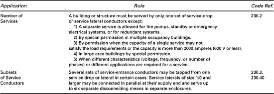
230.2
Number of Services. In general, a building may be served by only one set of service-drop or service lateral conductors, with the exceptions listed in Table 6–6. It is permissible to tap from two to six sets of service-entrance conductors to supply separate service-entrance enclosures if separate disconnecting means are supplied for each circuit.
Table 6–6. Number of Services Allowed
230.24
Installation Rules for Overhead Services. When overhead service-drop conductors are installed, a minimum specified clearance over roofs, from ground, and from building openings is required. These clearances are listed in Table 6–7 and some examples are illustrated in Figure 6–4.
Figure 6–4. Required Clearance of Service-Entrance Conductors over Roofs and from Ground
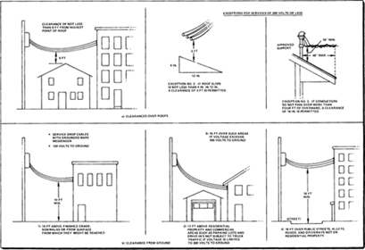
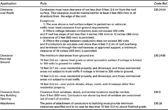
Table 6–7. Clearance for Overhead Services of 600 Volts or Less
Installation Rules for Service-Entrance Conductors. The Code specifies that service-entrance conductors must not be bare, but the Code lists several conditions under which the grounded conductor may be bare. The Code also limits the methods that may be used to install service-entrance conductors. These wiring methods are listed in Table 6–8 and are discussed in further detail in Chapter 7 of this Guide.
Table 6–8. Installation Rules for Service-Entrance Conductors and Service Equipment
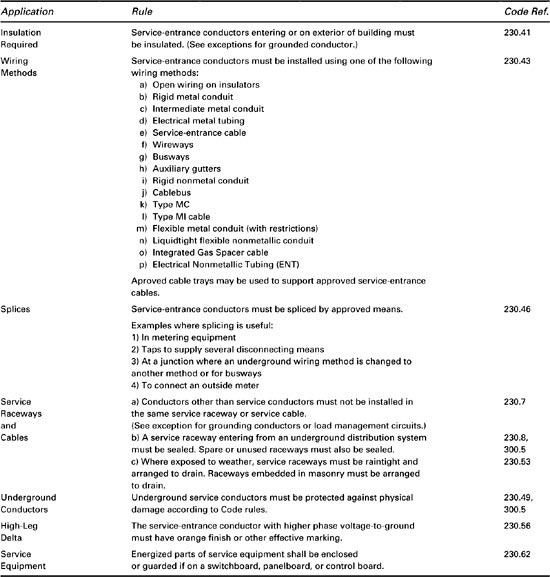
230.46, 230.7
230.62
230.49, 230.50
Service-entrance conductors may be spliced using approved means. If they are installed in a raceway, no other conductors other than grounding conductors or load management control conductors may share the same raceway. In general, energized parts of service equipment including the termination of service-entrance conductors must be enclosed to prevent contact unless they are guarded as described in Chapter 8 of this Guide. Every service conductor must also be protected from physical damage whether installed underground or above ground.
Protection, Support, and Installation of Service Conductors. The Code specifies the method of protection and support of service conductors when run above ground. Connection of service conductors on a building to supply the service equipment must be by an approved method and must meet the requirements stated in the Code.
ARTICLE 338
Service-entrance conductors may be individual conductors or part of a service-entrance cable. Type SE (service-entrance) cable is an approved wiring method used specifically for service-entrance conductors. In any case, if individual conductors or cable might be subject to physical damage, the Code rules listed in Table 6–9 must be followed.
Table 6–9. Protection, Support, and Installation of Service Conductors
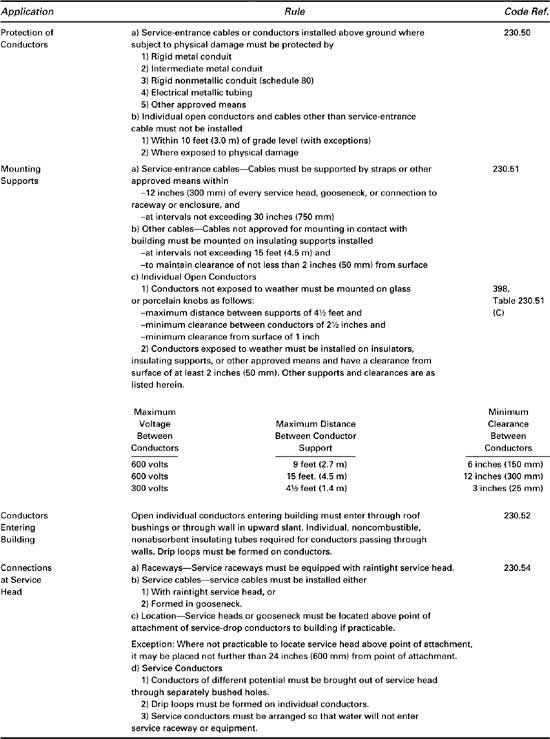
230.51
When service-entrance cable is used to connect the service equipment to the service-drop conductors, the cable must be supported as shown in Figure 6–5(a). Other cables not approved for mounting in contact with a building must maintain a clearance of 2 inches (50 mm) and be supported at least every 15 feet (4.5 m).
Figure 6–5. Installation Rules for Service-Entrance Conductors
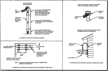
Open individual conductors supported on buildings must meet the clearances and distances between supports summarized in Table 6–9. Figure 6–5(b) illustrates the rules for installing open individual conductors that are not exposed to weather. If any open individual conductors enter a building, approved methods of passing conductors through a roof or wall must be used.
230.54
Figure 6–5(c) illustrates the most commonly used method of connecting service-entrance conductors to the service-drop conductors. When a service head and a service raceway are used, as shown, the service-entrance conductors are brought out of the service head and are spliced to the service drop. A raintight service head with individual bushings for each conductor must be used so that the whole arrangement does not allow water to enter the service raceway or equipment. Normally, the service head is located above the point of attachment of the service-drop conductors to a building; if this is impractical, the location must be within 24 inches of the point of attachment.
6–3.2 Installation Rules for Service Disconnecting Means and Overcurrent Protection
Each service requires a disconnecting means to disconnect all conductors in a building from the service-entrance conductors. In addition, each service-entrance conductor must be protected from overcurrent created by overloads or short circuits. Specific installation rules from the Code for the disconnecting means and for the overcurrent protective device at the service are discussed in this section.
230.71
230.72(C)
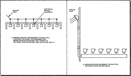
Service Disconnecting Means. The rules for the disconnecting means summarized in Table 6–10 restrict a disconnecting means to be not more than six switches or six circuit breakers. These devices may be mounted in a single enclosure, on a switch-board, or in a group of separate enclosures. In multiple occupancy buildings, separate disconnecting means and metering equipment are commonly provided for each occupant. In multiple-occupancy buildings, each occupant must have access to his disconnecting means with certain exceptions.
Table 6–10. Installation Rules for Service Disconnecting Means
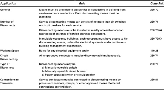
Figure 6–6. Location of Disconnects in Multiple-Occupancy Building
230.91
240.21
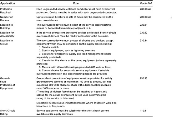
Overcurrent Protection. The Code rules listed in Table 6–11 specify that the overcurrent protective device or devices for a service must be placed in series with each ungrounded service-entrance conductor. The overcurrent protection is normally provided in the service enclosure, which also contains the service disconnecting means. In this arrangement the service-entrance conductors are not protected at their source of supply from the service-drop or lateral; instead, they are protected at their load end, as permitted by the Code.
Table 6–11. Installation Rules for Service Overcurrent Protection
230.90(A)
240.24(B)
230.72,
230.92
Service-entrance conductors may be protected by not more than six circuit breakers or six sets of fuses. In multiple-occupancy buildings, each occupant should have access to the disconnecting means and all overcurrent devices protecting the conductors supplying that occupancy. An exception is allowed if the building is under continuous building management supervision. In buildings with continuous electrical maintenance, the service and feeder overcurrent devices and disconnect are permitted to be made accessible to authorized personnel only. In such cases, a separate room for electrical equipment is typically provided in the building and the branch-circuit protective devices for each occupancy should be readily accessible to the occupant.
230.94
The service overcurrent protective device is required to protect all circuits and devices. This implies that all equipment must be connected on the load side of the overcurrent protective device. Exceptions are provided that permit the service switch and certain special devices (current-limiting devices, meters and other measuring devices, lightning protection devices, emergency and fire alarm circuits, etc.) to be connected on the supply side.
230.95
215.10
Ground-fault protection is required for solidly grounded wye services operating at more than 150 volts to ground and less than 600 volts phase to phase if the rating of the service disconnecting means is 1000 amperes or more. Thus, a 480Y/277-volt system with a 1000-ampere disconnecting means would require such protection. This provision is intended to protect equipment from a fault current resulting from a line-to-ground fault on the load side of the overcurrent protective device. Without such protection, the protective device may be set so high that it will not open the circuit because of the current drawn by the fault; a fire or other damage could result from the ensuing arc between the faulted conductor and ground. Such protection is required for a feeder disconnect rated 1000 amperes or more in a solidly grounded wye system operating at more than 150 volts to ground and less than 600 volts phase to phase except when such protection is provided on the supply side of the feeder.
6–3.3 Grounding and Bonding at Services
ARTICLE 100 DEFINITIONS
In a premises wiring system it is often required that a grounded conductor for the system be provided. The noncurrent-carrying metal parts of service equipment must also be connected together and grounded at the service. This grounding is actually accomplished by electrically connecting the grounded conductor and the equipment together and providing a conducting path to earth. As discussed in this section, this path consists of a grounding electrode conductor connected to a grounding electrode in intimate contact with the earth.
Bonding is the permanent joining of metal parts to form an electrically conductive path. Equipment and conductors required to be grounded at the service must be bonded together as described in this section.
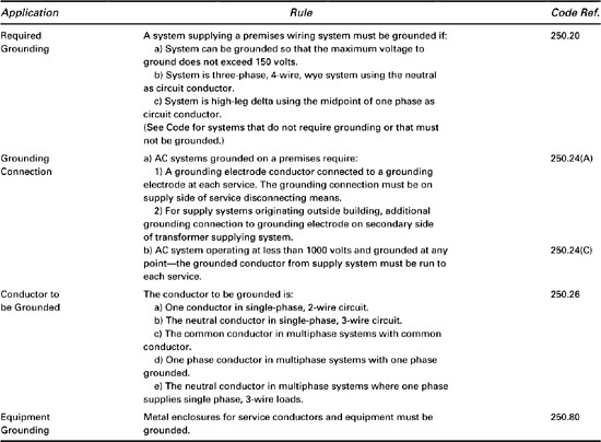
250.20
Grounding of Systems and Service Equipment. The Code requires a grounded circuit conductor in many alternating-current systems to limit or stabilize the voltage to ground. An ungrounded conductor may attain any voltage with respect to the earth. Hence, unless one conductor is grounded, a system with a fixed potential difference between conductors may not have a known voltage to ground. In most cases, this is not desirable. As listed in Table 6–12, the Code specifies the circuits to be grounded and the method of grounding.
Table 6–12. General Requirements for Service Grounding
Many alternating-current system operating between 50 volts and 1000 volts require grounding as shown in Figure 6–7(a). Grounding is required on any system that can be grounded in such a manner that the maximum voltage to ground does not exceed 150 volts, such as the common 120/240-volt system. Other systems that must be grounded include 480Y/277-volt services and the 240/120-volt high-leg delta service. Exceptions are made for special circuits such as control circuits and systems requiring isolation.
Figure 6–7. System Grounding Requirements
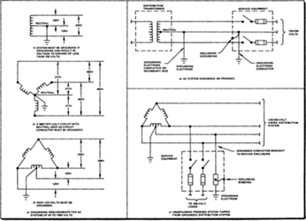
250.24(A)
In addition to these specific cases, a system grounded on the premises requires a grounding electrode at each service. If the supply system originates outside the building, a second grounding electrode is required at the transformer. Figure 6–7(b) shows a 120/240-volt system with the required grounding electrode conductor connections to the grounding electrodes. A grounding electrode is required at the service connected to the grounding electrode conductor on the supply side of the service disconnecting means. The other grounding electrode conductor is connected to the transformer on the secondary side.
Figure 6–7(c) shows an ungrounded premises system tapped from a grounded distribution system. The premises system requires grounding even though the loads do not use the neutral conductor. A grounded conductor must be brought to the enclosure for the disconnecting means to connect the grounding system at the service to that of the distribution system.
250.26
250.80
The Code also specifies which conductor is to be grounded for various alternating-current systems, as the examples of Figure 6–7(a) show. Another general rule requires that metal enclosures for service conductors and equipment be grounded.
Rules for service grounding specify requirements for grounding both circuits and equipment. Grounding of the distribution system and grounding at the service as just described provide a path to earth outside the building if the outside circuits are struck by lightning. Thus, equipment and interior wiring are protected. Equipment grounding is required so that personnel are protected from contacting accessible metal equipment that is not at earth potential.
If an ungrounded conductor were to accidentally contact an ungrounded metal object, that object would assume the potential of the conductor with respect to the earth. A fault would then have occurred in the system. A person touching the metal object would be subjected to the voltage of the conductor, causing a fault current to flow through the person’s body, with possible serious consequences. Grounding metal objects assures that any contact between the object and an ungrounded conductor would draw excessive current (since the resistance is low) and cause the circuit overcurrent protective devices to open the circuit.
250.130
A well-protected system is grounded so that all metal equipment required to be grounded is electrically connected to the grounding electrode system at the service, thus providing a low resistance path to earth if a fault were to occur. If the system has a grounded circuit conductor, this must also be electrically connected to the grounding electrode system at the service to assure one common grounding point for both circuits and equipment. The grounded circuit conductor must be grounded only at this point to assure current flow through the conductor rather than through the equipment or the earth. The Code rules for bonding specify how the grounding connections must be made using bonding jumpers.
250.92
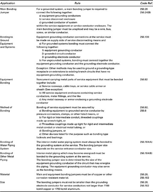
Bonding at the Service. The rules for service bonding specify the required bonding, the methods of bonding, and the sizes of the bonding conductors. Table 6–13 summarizes these rules for bonding.
Table 6–13. Rules for Bonding at the Service
Bonding jumpers at the service connect conductors and equipment to assure electrical continuity for adequate grounding. A bonding jumper is not necessarily a wire, but it must maintain the required electrical continuity between metal parts required to be grounded.
250.28
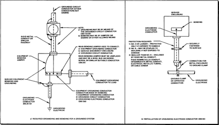
The grounded system in Figure 6–8(a) requires a main bonding jumper to connect the equipment grounding conductors and the service disconnect enclosure to the grounded circuit conductor. The main bonding jumper may be a wire, bus (as shown), screw, or similar conductor within the service equipment enclosure.
Figure 6–8. Grounding and Bonding of Services
250.130
The grounding connection between the circuit, equipment, and the grounding electrode conductor is provided by bonding the equipment grounding conductors to the grounding electrode conductor and thus to the grounding electrode system. If the system is grounded, the grounded circuit conductor must also be bonded to this connection.
250.92
Equipment grounding requirements refer to service equipment as well as noncurrent-carrying metal parts of other equipment and raceways that are part of the system. The service equipment must be bonded together, as described in Table 6–13, and then grounded. Any equipment grounding conductors from utilization equipment supplied by the system must also be connected together and grounded at the service.
250.142
The method of grounding equipment at the service is by bonding to the grounding electrode conductor as previously described, except that specific equipment on the supply side of the service disconnecting means, such as meter enclosures and metal service raceways, may be grounded by the grounded circuit conductor of the service conductors.
250.104
250.104(B)
In addition to the conductors and equipment that must be bonded together and grounded, the Code specifies that interior metal piping and structural steel that may become energized must be bonded to the service equipment enclosures and to the grounded conductor at the service. The size of the service-entrance conductors determines the size of the bonding jumper for a water piping system. However, the size of the jumper required for other metal pipes depends on the rating of the circuit that may energize the piping.
250.28,
250.102
The Code further specifies that the main bonding jumper and equipment bonding jumpers on the supply side of the service must be of copper or other corrosion-resistant material. The size must not be less than that of the grounding electrode conductor for service-entrance conductors as large as 1100 kcmil copper or 1750 kcmil aluminum.
250.24
250.32
The Grounding Electrode Conductor. Any grounded premises wiring system requires a grounding electrode installed according to the Code rules listed in Table 6–14. This conductor connects equipment grounding conductors, service equipment enclosures, and the grounded circuit conductor to the grounding electrode. If a single service supplies several buildings, each building, in most cases, requires a grounding electrode. The Code also specifies rules for grounding separately derived systems supplied from a generator, transformer, or similar unit.
Table 6–14. Installation Rules for Grounding Electrode Conductor
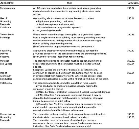
250.64
The grounding electrode conductor must be copper, aluminum, or copperclad aluminum and must be resistant to any corrosive condition at the installation. In fact, the Code restricts the use of aluminum or copperclad aluminum conductors. These conductors must not be used in direct contact with masonry or the earth or outside within 18 inches of the earth.
Figure 6–8(b) illustrates rules for installing the grounding electrode conductor. The conductor or its enclosure must be securely fastened to the surface on which it is carried. If the conductor is No. 4 or larger, it requires no protection unless it is exposed to severe physical damage. A No. 6 conductor not exposed to physical damage need not be protected either, and it may be stapled to the building. Conductors smaller than No. 6 or a No. 6 conductor subject to physical damage must be enclosed in a raceway of the type listed in the Code.
250.70
If the grounding electrode conductor is enclosed in a metal raceway, the raceway must be electrically continuous from the service equipment to the grounding electrode and it must be connected to the ground clamp or fitting at the electrode. The ground clamp or other means that connects to the grounding electrode itself must be a listed type without solder connections.
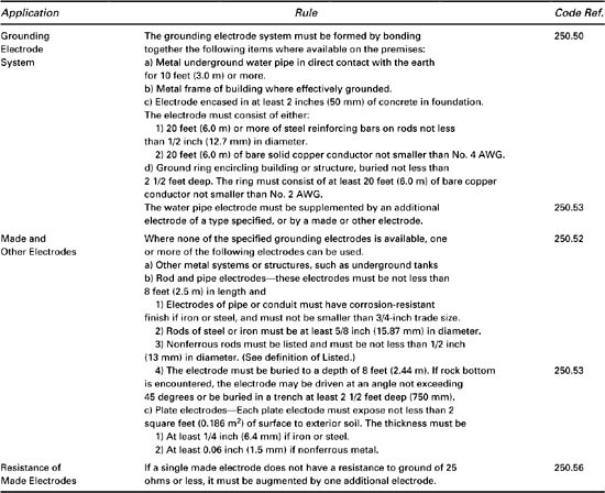
250.50
250.52
250.56
The Grounding Electrode. The most commonly used grounding electrode for a building has been an underground metal water piping system at least 10 feet long. A Code rule change in 1978 required that this electrode be supplemented by an additional electrode, either available on the premises or specially constructed for the purpose (made electrode). An acceptable grounding electrode system including various supplemental electrodes for a building is illustrated in Figure 6–9(a). All the elements of the grounding system must be bonded together as listed in Table 6–15, including the water pipe, other available electrodes, and any made electrodes that are used. The supplemental electrodes at the building served could include the grounded metal frame of the building, steel reinforcing bars or rods at least 20 feet (6 m) in length and ½-inch or more in diameter encased in 2 inches (50 mm) of concrete, or a length of copper conductor. If none of these additional electrodes is available, a made electrode or other electrodes must be used to supplement the water piping system. If a made electrode must be used, the various types of electrodes shown in Figure 6–9(b) are acceptable. Note that gas piping systems and aluminum electrodes are not permitted for use as grounding electrodes. For made electrodes, the Code specifies a maximum resistance to ground of 25 ohms. If the measured resistance exceeds this value, one additional electrode must be used to augment the grounding electrode system.
Figure 6–9. Grounding Electrode System
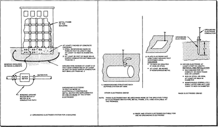
Table 6–15. Installation Rules for Grounding Electrode
6–4 Systems Operating at Over 600 Volts
ARTICLE 490
The Code provides specific rules for systems operating at more than 600 volts. These rules supplement or modify the rules for general installations. Although a separate Code article is devoted to high-voltage systems, various rules for specific installations are set forth throughout the Code. The reader should refer to Chapter 12 of this Guide for a discussion of installation rules applicable to such systems.
6–5 Miscellaneous Circuits and Systems
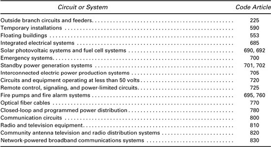
Code references to installation rules for miscellaneous circuits and systems are listed in Table 6–16. The reader should refer to the Code text in order to gain a complete understanding of the Code rules applicable to these specific circuits and systems. Several of these circuits or systems are discussed in Chapter 12 of this Guide.
Table 6–16. Miscellaneous Circuits and System