Chapter 13
Review of Electrical Theory
This chapter presents a brief review of electrical theory consistent with the level presented in the Guide and in the various examinations. The areas of direct-current theory, conductors, alternating-current theory, and equipment in alternating-current circuits are discussed. Important formulas for problem solving in these areas are listed in Appendix A for convenient reference. The test in this chapter requires the application of these formulas to solve problems typical of many electrician’s examinations.
13–1 Direct-Current Theory
The calculation of current and voltage in a direct-current circuit containing only resistive elements is determined by Ohm’s law. This basic law states that the voltage across a resistive element is equal to the resistance of the element times the current through the element or
![]()
where E is the voltage, I is the current in amperes, and R is the resistance in ohms. The power dissipated by the resistance R is given by
![]()
When resistive elements are connected in a circuit, it is possible to combine the resistances to obtain a total resistance for the circuit. Then Ohm’s law applies to the entire circuit if R in the equation above is taken to be the total resistance. Various formulas for combining resistive elements are given in Table A–1 of Appendix A. Review problems for direct-current circuits are contained in Part I of the test for this chapter.
13–2 Conductors
A conductor used in electrical circuits has a resistance that increases with its length and decreases with its area. The relationship is expressed as
![]()
where L is the length in feet, A is the area in circular mils, and ρ is the resistivity which depends on the material and the temperature.
The circular mil area is the square of the diameter of the wire in mils. Thus, a wire of diameter one-thousandth of an inch (.001 inch) has an area of 1 circular mil (cmil). The true area in square inches is given by
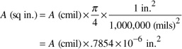
This formula is useful in converting between the area of a rectangular bus bar and that of a circular conductor since the current-carrying capacity of either depends on the area. Thus, they can be compared.
For large conductors, the circular mil area is measured in thousands of circular mils or kcmil. Thus, a 1000-kcmil conductor has an area of 1,000,000 cmils, a diameter of 1000 cmils or 1 inch, and an area of .7854 square inches.
The resistivity of the conductor depends on the material, either aluminum or copper, in most applications. The units of resistivity are ohms per circular mil-foot, which measures the resistance of a conductor 1 circular mil in area and 1 foot long. Typical values at 25°C (77°F) are as follows:
a. Aluminum 17.7 ohms—cmil/foot
b. Copper 10.5 ohms—cmil/foot
These values apply at the temperature stated and would increase with increasing temperature. The values at 75°C (167°F) are approximately 12.6 for copper and 20.6 for aluminum.
TABLE 8, CHAPTER 9
Many tables list the resistance of conductors in ohms per 1000 feet. Thus, if the length of a given size conductor is known, its resistance may be determined from the appropriate table. The code values are given at 75°C (167°F).
Selected formulas are listed in Table A–2 of Appendix A to aid in the solution of problems presented in Part II of the test for this chapter.
13–3 Alternating-Current Theory
The alternating-current voltage or current waveform is characterized by its amplitude, frequency, and phase angle. The amplitude is the value of the wave at its maximum or peak and the frequency is the number of times the wave repeats its full cycle during 1 second. If this occurs 60 times per second, the frequency is 60 hertz (Hz). The period of the wave is the time duration of each cycle or the reciprocal of the frequency given by
![]()
where T is the period and f is the frequency in hertz.
The phase angle determines the shift in time of the wave from a reference point, with 360° being a shift of one entire cycle. In circuits that contain inductance or capacitance the voltage and current waveforms are not in phase but are shifted by a phase angle that depends on the properties of the circuit.
An important result of alternating-current theory is that a sinusoidal waveform such as the common 60-Hz power distribution wave can be represented by its root mean square (rms) value. This value is obtained by dividing the peak value by the square root of 2. A voltage wave with a peak of 162.6 volts has a root mean square value of 162.6 ÷ 1.414 = 115 volts. The alternating-current waveform is then characterized by its root mean square value, frequency, and phase angle.
A brief review is given in this section of inductors and capacitors, impedance, power, and power factor in ac circuits. Table A–3 in Appendix A contains summary formulas for the problems in Part III of the chapter test.
13–3.1 Inductors and Capacitors
In addition to resistors, ac circuits often contain inductors and capacitors. These elements are characterized by their inductive reactance and capacitive reactance, respectively. When an ac voltage is applied to either circuit element, the voltage and current waveforms are not in phase. However, the root mean square magnitude of the current I is related to the root mean square value of the voltage V across an inductor or capacitor by the expression
![]()
where X is the reactance of the element as given by formulas in Table A–3. This reactance is measured in units of ohms.
13–3.2 Impedance
Impedance, abbreviated ![]() , is the ratio of the voltage to the current in an ac circuit. Since the voltage and current may be out of phase, a phase angle is associated with the impedance. However, the magnitude of
, is the ratio of the voltage to the current in an ac circuit. Since the voltage and current may be out of phase, a phase angle is associated with the impedance. However, the magnitude of ![]() written Z, depends only on the resistance and reactance of the circuit elements as shown in Table A–3 and is the ratio of the root mean square voltage to the root mean square current.
written Z, depends only on the resistance and reactance of the circuit elements as shown in Table A–3 and is the ratio of the root mean square voltage to the root mean square current.
13–3.3 Power and Power Factor
Power is the rate of doing work. The average power is associated only with resistive elements in a circuit. Capacitors and inductors store and release energy during each cycle of the ac wave, but they do not absorb or generate power on the average. However, their effect in a circuit is determined by their rating in volt-amperes reactive or VARS. This value is calculated as follows:
![]()
where I is the root mean square current through the element and X is the reactance. The rating in VARS for a capacitor or inductor is mathematically similar to the power in a resistor in watts.
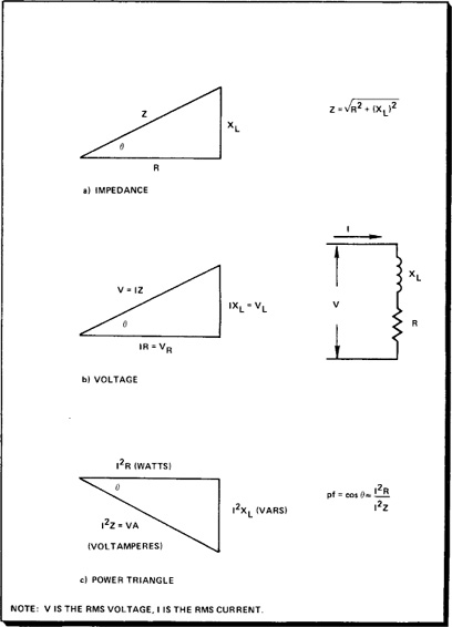
To combine the power in watts and the voltamperes reactive to determine the “apparent” power or volt-ampere requirement of a circuit, the power triangle is drawn. The adjacent side represents power in watts, and the opposite side at 90° is the reactive component. The hypotenuse becomes the volt-ampere component. Figure 13–1 shows the impedance, voltage, and power relationships in an ac circuit and defines the phase angle between the power and the volt-ampere component for a series circuit consisting of a resistor and an inductor. The reactive component in the power triangle is drawn down to indicate that the current has a lagging phase angle with respect to the voltage. In a capacitive circuit the reactive component would be drawn upward by convention.
The power factor is the cosine of the phase angle which is calculated as
![]()
In the circuit shown in Figure 12–1 the power factor is given by
![]()
since the same current flows in each element.
When the power factor of a circuit is known, the power can be calculated from the volt-ampere product for the circuit. If the root mean square voltage and current are known, then
![]()
for a single-phase circuit. In a balanced three-phase circuit
![]()
13–3.4 Power Factor Correction
To improve the power factor of a load, inductance or capacitance must be added to the circuit to reduce the reactive volt-ampere rating of the circuit. The ideal power factor is unity since the input volt-ampere rating is then converted entirely to power in watts. This is not always possible, but an increase in the power factor of the circuit is desirable. The formulas of Table A–3 give correction calculations in terms of the power and the new desired power factor of the circuit.
13–3.5 Energy (Watt-Hours)
The electrical energy supplied to a circuit is measured as the power consumed over a specified period of time. This energy is measured in watt-hours or kilowatt-hours as follows:
![]()
Figure 13–1. Relationships in Alternating-Current Circuits
The kilowatt-hour is the energy resulting from the power of 1 kilowatt operating for 1 hour.
In certain circuits the units of watts, volt-amperes, or volt-amperes reactive may be too small for convenient measurement. These units in thousands become kilowatts (kW), kilovoltamperes (kVA), and kilovoltamperes reactive (kVAR), respectively.
13–4 Equipment in AC Circuits
When equipment is supplied by an ac circuit, the calculation of the voltage, current, or volt-ampere requirement is based on the characteristics of the circuit and the equipment. A given single-phase or three-phase load draws a current at its rated voltage that is easily determined by basic ac theory. However, the voltage at the load may be less than the source voltage because of the voltage drop in the supply conductors. When the voltage drop is expected to be significant i.e., more than several percent of the supply voltage, it should be calculated as shown in this section.
The specific equipment considered in this section includes transformers and motors. The important formulas are summarized in Table A–4 and problems related to equipment in ac circuits are given in Part IV of this chapter’s test.
13–4.1 Loads
Each item of ac equipment represents a load for the supply circuits whose capacity must be great enough to supply every unit. The rating of the load is normally specified in watts for purely resistive loads or in volt-amperes for loads with reactive characteristics. The total load for a circuit or system determines the required rating of the generating equipment and any transformers used to stepup or stepdown the voltage of the system. The size or rating of conductors and overcurrent protective devices is based on the current drawn by the loads.
In single-phase and balanced three-phase circuits the current in amperes is calculated by using the formulas presented in Table A–4. The line current for each circuit depends only on the voltage and the volt-ampere rating of the load.
If the load of a three-phase circuit is unbalanced, the individual phases of the circuit draw currents that depend on the load of each phase. The calculation of the load currents involves ac theory beyond the scope of this Guide, but the calculation is treated in several of the references mentioned in the Bibliography of this Guide.
13–4.2 Voltage Drop in Conductors
Since a conductor has a resistance that depends on its size and length, the current flowing in a conductor causes a voltage drop between the source and the load. This voltage drop for a single conductor is the product of the current times the resistance of the conductor as given in Table A–4.1 This drop is not, however, the voltage drop for the entire circuit since at least two conductors are required for any circuit, with three or four required in three-phase circuits.
1The voltage drop calculations given in this section must be modified for any of the following conditions: (1) the power factor of the load is not 1.0, (2) the inductance of the circuit cannot be neglected, or (3) the ac resistance of the conductors must be considered. The American Electricians Handbook listed in the Bibliography explains procedures in these cases.
The voltage drop for a circuit is defined as the difference between the voltage of the source and voltage at the load expressed as
![]()
The percentage voltage drop in terms of the source voltage is
![]()
Thus, a two-wire, 230-volt source supplying 220 volts at the load has a 10-volt or 4.3% voltage drop.
In two-wire, single-phase circuits the voltage drop is calculated as
![]()
where R is the resistance of one of the supply conductors. The value of R is determined from tables of conductor resistance based on the length of the conductor. The formula also may be used to determine the voltage drop for three-wire, single-phase circuits with a balanced load. In these circuits there is no current in the neutral conductor and hence no voltage drop from line-to-neutral.
Three-wire, three-phase circuits with a balanced load have a voltage drop determined as
![]()
where the factor .866 (![]() /2) is due to the three-phase circuit and the other values represent the two-wire voltage drop in a single-phase circuit. Rewritten, the formula becomes
/2) is due to the three-phase circuit and the other values represent the two-wire voltage drop in a single-phase circuit. Rewritten, the formula becomes
![]()
where I is the line current and R is the resistance of one of the conductors supplying the three-phase load. Thus, a 480-volt, three-phase circuit supplied by conductors with 1-ohm (Ω) resistance which carry 1 ampere has a voltage drop of
![]()
and a percentage voltage drop of .36%.
In a balanced, three-phase, four-wire circuit the line-to-neutral voltage drop is
![]()
or one-half of the two-wire drop in a single-phase circuit.
13–4.3 Transformers
Transformers are used in ac systems to change the voltage level of a distribution system or service when required. Depending on the turns ratio of the primary and secondary windings, the voltage may be increased or decreased. Since the volt-ampere rating of the primary is equal to that of the secondary in an ideal transformer, the ratio of primary to secondary current must change as indicated by the formulas in Table A–4.
13–4.4 Motors
There is extensive literature covering the characteristics and use of motors in ac circuits. From this wealth of information only a few basic principles concerning speed, efficiency, and power factor are presented here.
The speed of a synchronous motor is determined by the frequency of the ac voltage waveform and the number of poles the motor contains. The speed is proportional to frequency and decreases with the number of poles as shown in Table A–4.
In order to calculate the power output of a motor, the input power and the efficiency must be known. These quantities are related by the equation
![]()
where η is the efficiency. Normally, the power input is measured in watts and the output power is measured in horsepower where 1 horsepower equals 746 watts. When a motor has a power factor, the input power is the volt-ampere input times the power factor.
The power factor of a motor may be improved by adding a capacitor to the circuit to cancel the lagging reactive component of the motor load. Once the reactive component is determined, the value of the capacitor to correct or increase the power factor is found as discussed in Section 12–3.
13–4.5 Electrical Diagrams
The reader should be familiar with the wiring diagrams and elementary or one-line diagrams for transformers, motors, and motor controllers. The wiring diagrams show the complete electrical system and the connection of each element. Since the complete diagram is very detailed, interpretation is sometimes difficult and the simpler elementary diagram is used. The elementary diagram is intended to yield a clear picture of the operation of a circuit, but it is not detailed enough to be followed when a circuit is being wired.
TEST CHAPTER 13
I. Basic dc Theory
1. What is the current in a series circuit consisting of resistors of 20 ohms, 10 ohms, and 30 ohms supplied by a 100-volt source?
2. A 20-ohm and a 15-ohm resistor are in series with a 120-volt source. What is the voltage across the 15-ohm resistor? What power is dissipated by the 15-ohm resistor?
3. Two 600-watt heaters are connected in series to a 120-volt source. What is the current in the circuit and what is the resistance of each heater?
4. What is the equivalent resistance of a 20-ohm and a 40-ohm resistor in parallel?
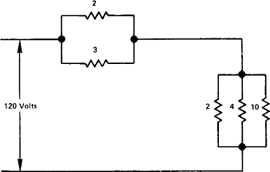
5. In the circuit shown below find the current from the 120-volt source. The values given are in ohms.
II. Conductors
1. What is the circular mil area of a No. 10 conductor whose area is .008155 square inches?
2. Calculate the dc resistance of 100 feet of copper wire .102 inches in diameter at 75°C.
3. It is required to replace a .75-inch × 1 inch bus bar with a conductor that carries the same current. Determine the kcmil size of the conductor.
4. Calculate the dc resistance of 400 feet of No. 12 solid copper conductor at 75°C.
5. What is the dc resistance of four No. 1/0 aluminum conductors in parallel for a length of 1000 feet?
6. Calculate the ratio of the square mil area to the circular mil area for a conductor ¼ inch in diameter.
7. What is the diameter of a conductor 15,625 circular mils in area?
III. ac Theory
1. What is the period of a 60-Hz ac waveform?
2. In a 60-Hz ac waveform a phase shift of 60 degrees represents what shift in time?
3. A coil without resistance connected to a 150-volt, 60-Hz supply draws 3 amperes. Calculate the reactance and the inductance.
4. A coil with 5 ohms of resistance and 12 ohms of reactance is connected to a 120-volt supply. What is the current in the coil?
5. Compute the power factor of the coil in problem 4.
6. A resistor of 20 ohms and a capacitance of 31.8 ohms reactance are connected in series to a 200-volt ac source. Calculate (a) the current, (b) the voltage drop across the resistor, and (c) the power delivered by the source.
7. A capacitor connected to 240-volt source draws 120 amperes. What is the rating of the capacitor in VARS?
8. A 50-kilowatt load has a lagging power factor of .8. If the line voltage is 240-volts, find (a) the kilovolt-amperage for the load and (b) the current.
9. A balanced, three-phase load connected to a 208Y/120-volt supply has a power factor of .75 and draws 50 amperes. Calculate the power of the load.
10. A 10-kilowatt load operates continuously. What is the energy consumption in 1 day?
11. A 25-kilowatt load has a lagging power factor of .6. Determine the kilovolt-ampere reactive rating of the load and the value of the capacitive reactance to increase the power factor to .80.
1. Two 50-kilowatt, 240-volt, single-phase loads are connected to a circuit. First, determine the currents drawn by each load if the power factors are 1.0 and .8, respectively. Next, combine the two loads and calculate the overall power factor, required kilovolt-amperes, and current.
2. A balanced 30-kilowatt load is connected to a 480-volt, three-phase supply. If the power is .75, find the supply current.
3. Calculate the voltage drop and percentage voltage drop if No. 10 copper conductors supply loads 1000 feet away. The individual loads have the following characteristics: (a) single-phase, 200-volt load with resistance of 18 ohms; (b) three-phase, 230-volt load of 2 kilowatts; (c) 2-kilowatt, 277-volt load supplied by a 480Y/277-volt circuit.
4. What size copper conductor is required to limit the voltage drop of a 50-ampere, 120-volt, single-phase load to less than 3% if the load is 300 feet away.
5. Determine the primary and secondary rated current for a 480/208/120-volt, 300-kilovolt-ampere transformer.
6. Determine the speed of a four-pole ac motor connected to a 60-hertz supply. What would the speed be if the supply frequency were 120 hertz?
7. A 460-volt, three-phase motor has a power factor of .8 and an efficiency of .85. If the motor draws 75 amperes, determine the horsepower delivered by the motor.
8. Using the appropriate Code tables, determine the efficiency of the following motors: (a) 1-horsepower, 115-volt, single-phase; (b) 5-horsepower, 115-volt, single-phase; (c) 1-horsepower, 460-volt, three-phase; (d) 100-horsepower, 460-volt, three-phase.
9. A 460-volt, three-phase, 50-horsepower motor has a power factor of .7. Determine the required rating of the capacitor to raise the power factor to 1.0.