
Chapter 9. Static and Dynamic Architecture
Systems have a static and a dynamic architecture. The static architecture is represented by a collection of components that are structured in a component hierarchy. For each component in the hierarchy, its component implementation defines the internal structure in terms of subcomponents and interactions in terms of connections. The dynamic architecture is represented by a collection of component and connection configurations that are controlled by modes. Modes effectively represent operational modes and fault tolerant configurations of both software and hardware, as well as modal behavior of individual components. In this chapter, we discuss subcomponents and arrays of subcomponents to represent the static architecture, as well as modes and mode transitions to represent the dynamic architecture. Component interactions in terms of connections and information flows throughout the system are discussed in subsequent chapters.
9.1. Subcomponents
A subcomponent declaration defines a component instance by referencing a component type or implementation. This reference identifies a pattern for the subcomponent that defines the category and characteristics of that instance.
9.1.1. Declaring Subcomponents
The template for a subcomponent declaration for a subcomponent follows:
name : <component category> [component reference]
[{properties}] [in modes];
Both a subcomponent name and a component category are required. The entry <component category> must be replaced by one of the legal AADL component categories, such as thread, process, memory, or abstract. The name of a subcomponent is a single AADL identifier. This identifier must be unique within the component implementation (i.e., you cannot have two subcomponents with the same name, or a connection and a subcomponent with the same name).
The component reference identifies a component type or component implementation whose instance the subcomponent represents. The reference can be to a component type or implementation within the same package (e.g., core_system) or in a different package (e.g., data_pkg::set_points). The subcomponent name can be the same as the name of the component type in the component reference. The component reference is optional for a partially complete component implementation. Similarly, property associations are optional. Finally, you only need to declare in modes if the subcomponent is part of a component implementation with modes and the subcomponent is only active in certain modes. Example subcomponent declarations are shown in Listing 9-1.
Listing 9-1. Example Subcomponent Declarations
control_process: process controller.speed
in modes (init, operational);
set_point_data: data data_pkg::set_points;
navigation_system: system core_system;
real_time_processor: processor rt_fast.rt_processor;
marine_bus: bus hardware_pkg::marine_bus;
marine_certified_RAM: memory { Memory_Protocol => read_write;};
init_process: process init_process in modes (init)
9.1.2. Using Subcomponent Declarations
Subcomponents are declared within the subcomponents section of a component implementation and define component instances that are contained within that implementation. Since a contained component may itself contain subcomponents, subcomponent declarations can be used to establish a compositional component hierarchy. For example, a control system component can contain a system component that itself contains a directional control system. The directional control system can contain a process, which contains a thread that provides the control law algorithm processing. This is shown in Listing 9-2, where the system implementation basic.speed_control contains three subcomponents. The subcomponent declaration of speed_control references the process implementation control.speed, which contains two thread subcomponents.
Listing 9-2. Defining a Component Hierarchy with Subcomponent Declarations
system implementation basic.speed_control
subcomponents
speed_sensor: device sensor.speed;
throttle: device actuator.speed;
speed_control: process control.speed;
end basic.speed_control;
--
process implementation control.speed
subcomponents
scale_speed_data: thread read_data.speed;
speed_control_laws: thread control_laws.speed;
end control.speed;
thread implementation read_data.speed
end read_data.speed;
thread implementation control_laws.speed
end control_laws.speed;
Each component category allows certain other component categories to be subcomponents. For example, you cannot place a thread within a system unless that thread is contained in a process or within a thread group that itself is contained within a process. This restriction is discussed for each category in the Constraints subsection of the respective chapter.
You can partially declare subcomponents by omitting the classifier reference or by simply specifying a component type. For example, consider the system implementation basic.directional_control shown in Listing 9-3. In the declaration only the type references are included for the GPS and rudder subcomponents and no classifier reference is used for the directional_control process subcomponent. The result is a partially complete system architecture model, in which some details have not been provided yet. You can still generate instance models from partially complete models and perform some analyses (e.g., you may be able to analyze resource budgets of processes). For other analyses, such as scheduling analysis, the model must include both processors and threads.
Listing 9-3. Partially Specified Subcomponents
system implementation basic.directional_control
subcomponents
GPS: device Basic_GPS;
rudder: device actuator;
directional_control: process;
end basic.directional_control;
9.1.3. Declaring Subcomponents as Arrays
A subcomponent can be defined as an array consisting of multiple instances of a single component classifier. These can be single or multidimensional arrays that are declared by including an array dimension within a subcomponent declaration. An array dimension consists of a size entry that is included before any optional property associations as shown in the box that follows.
name : <component category> [component reference] ( [size] )+
[{properties}] [(in modes)];
The size entry defines the number of dimensions and the size of each dimension using square brackets. The plus sign superscript on [size] indicates one or more bracketed entries. Each bracket represents a dimension of the array and an integer, integer property value, or integer constant within the bracket defines the number of elements (the size of the dimension). For example, a two-dimensional array of size two by three is declared as [2] [3]. Arrays may be specified with dimensions but without a size value. The size value is then provided for all dimensions of an array in a refinement declaration. The size value can be an integer, a property, or a property constant. By using a property or property constant you can parameterize the array size.
You can declare arrays at any level of a component hierarchy and for any component category. Examples of declaring array subcomponents are shown in Listing 9-4. The subcomponent sensor_network is a 4 by 4 array of instances of the device type radar_sensor. The process data_filters is a one dimensional array of size r_level, where r_level is an aadlinteger property defined in the property set ex_prop_set and assigned the value 3.
Listing 9-4. Array Subcomponents
subcomponents
sensor_network: device radar_sensor [4] [4];
data_filters: process filters.basic [ex_prop_set::r_level];
*****
ex_prop_set::r_level => 3;
You are able to declare subcomponent arrays of components that themselves contain subcomponent arrays. For example, you can declare a system called MemoryBoard that contains a single-dimensional array of memory components, and then declare a system called MemoryBox that contains a single-dimensional array of memory boards. The resulting instance model effectively has a two-dimensional array of memory instances.
9.2. Modes
A component can have modes and mode transitions. We can use modes to represent various operational states of a system or component. A mode can represent a configuration of active subcomponents and connections. These configurations can represent different operational configurations and different fault tolerant configurations. For example, during taxiing of an aircraft its autopilot is not engaged. Similarly, an aircraft may have a dual redundant flight guidance subsystem that operates nominally with both instances active, but continues to operate with one instance when the other instance fails. Mode transitions determine when the system is reconfigured dynamically to a new configuration.
Components can have property values that differ from mode to mode. For example, a thread can have different modes to represent an algorithm executing with different levels of precision and different execution times, or a processor can have different modes with different cycle times.
Modes can be used within threads or subprograms to specify different call sequences. This allows you to model the behavior of application code. The mode concept has some limitations in that role since it is primarily intended for architectural modeling. Therefore, you can make use of the Behavior Annex standard [BAnnex] or a state-based modeling language to represent the functional behavior of application components.
9.2.1. Declaring Modes and Mode Transitions
Modes are states within a state machine abstraction. They are declared in the modes section of a component type or implementation.
A mode declaration involves naming the mode, optionally identifying the mode as the initial mode, and declaring properties as desired. In the declaration, the reserved word mode must be included as shown in the template that follows.
name : [initial] mode [{properties}];
A mode transition declaration consists of a name (that is optional), source mode, triggers, and destination mode for the transition. All transitions involve a single source and a single destination mode. Multiple source or destination modes are not permitted, but you can declare several transitions originating in a particular mode or being the destination of a particular mode.
The template for a mode transition declaration is shown in the box that follows.
[ name :] (source mode) -[ (triggers) ]-> (destination mode) ;
Note that the brackets shown with the transition arrow are part of the mode transition symbols, not a designation of an optional entry. Rather, a mode transition symbol consists of two parts –[ and ]-> that enclose the triggers for the transition. The triggers for a transition are port names (event, event data, or data), a self.source_name declaration, or a processor.source_name declaration. The named ports can be those of the component itself to represent external events triggering mode transitions, or ports of subcomponents to represent events propagating up the component hierarchy and being handled by this component. You can also name events that are raised by the component itself such as fault event, or by the processor on which the application executes.
The arrival of events, data, or event data through a named port is the trigger for a transition. If the mode transition names more than one trigger, then the arrival of events, data, or event data on any of them results in a mode transition. In other words, the mode transition trigger condition is a logical or condition. The default or condition can be refined through an annex subclause into a more complex condition. Such conditions can be evaluated by application software, such as a health monitor, which then raises the mode transition trigger event.
9.2.2. Declaring Modal Component Types and Implementations
Modes can be declared within component types or implementations. When declared in a type, modes apply to all implementations of that type. There are two cases of mode declarations within component types. In the first case, modes are declared with mode transition declarations in a modes section. In this case, the mode state machine performs mode transitions according to the transition trigger specification. In the second case, modes are declared as inherited in a requires modes section. In this case, the component inherits the mode state machine from the enclosing component and operates in different modes according to the mode transition of the inherited mode state machine. Inherited modes are described in more detail in Section 9.2.4.
Mode transitions may be triggered externally through ports in a component type. In this case, the mode transitions can be specified in the component type. A mode transition may be triggered from within the component. In this situation, component implementations can add mode transitions that refer to the event ports of subcomponents. However, component implementations cannot add modes, if modes are declared in the component type.
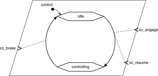
Examples of mode declarations are shown in Listing 9-5 that presents textual and graphical representations of modes and transitions for a simplified controller thread type control_modal. In this example, mode transitions are triggered by external events that enter through event ports. There are two modes, idle and controlling, and three event ports in this example. The idle mode is the initial mode. The event brought into the thread by the event port cc_engage results in a mode transition from the idle mode to the controlling mode (the thread configuration that provides the functionality to maintain a set speed). The event carried through the event port cc_resume1 also results in a switch to the controlling mode. The event port cc_brake results in an exit of the controlling mode and transition into the idle mode.
Listing 9-5. Example Modes Within a Type
thread control_modal
features
cc_engage : in event port;
cc_resume : in event port;
cc_brake: in event port;
modes
idle : initial mode;
controlling : mode;
idle -[ cc_engage, cc_resume ]-> controlling;
controlling -[ cc_brake]-> idle;
end control_modal;
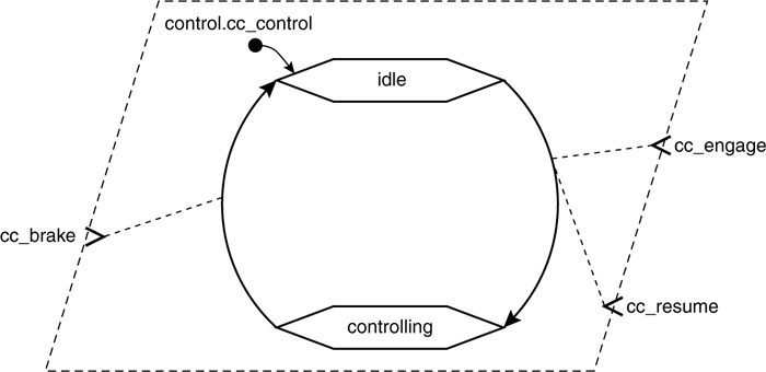
Listing 9-6 shows type and implementation declarations for a system with the same modes and transitions shown in Listing 9-5. However, the modes are declared in the implementation control_b.cc_control rather than in the type control_b. The lower portion of Listing 9-6 contains a graphical representation of the mode transitions for the implementation. Since no modes are declared in the type, other implementations of control_b could define alternative modes from those of control_b.cc_control.
Listing 9-6. Sample Graphical and Textual Specifications for Modes
thread control_b
features
cc_engage : in event port;
cc_resume : in event port;
cc_brake: in event port;
end control_b;
thread implementation control_b.cc_control
modes
idle : initial mode;
controlling : mode;
idle -[ cc_engage, cc_resume ]-> controlling;
controlling -[ cc_brake]-> idle;
end control_b.cc_control;
9.2.3. Using Modes for Alternative Component Configurations
Modes can be used to define alternative configurations of subcomponents and connections within an implementation. This can be done when the modes and their transitions are declared in the implementation or in its type. You indicate which subcomponents and connections are part of a mode by adorning subcomponents and connections with an in modes statement. Within threads and subprograms, you can do the same for call sequences. In addition, you can declare flow specifications, flow implementations, end-to-end flows, and property associations to be mode-specific with an in modes statement.
The template for an in modes statement is shown here.
in modes ( mode names )
The mode names entry is a single mode name, or a list of mode names separated by commas. Note that the parentheses are required around mode names entries. The mode name must refer to a mode declared within the component or as inherited by the component through the requires modes section. You can also specify that a connection is only active during a mode transition. In this case, you refer to the mode transition name in the in modes statement of the connection declaration. This capability is useful if you want to model that data is transferred from a component that is deactivated to a component that is activated during a mode transition.
The example in Listing 9-7 shows a multimode process control_algorithms.impl. In the textual specification for the process control_algorithms.impl, the modes section defines the two operational modes of ground and flight and the transitions between them. The transitions are triggered by out event ports from the thread controller that is a subcomponent of the process implementation control_algorithms.impl. The subcomponent thread controller is active in all modes, whereas the thread flight_algorithms is active only in the flight mode and the thread ground_algorithms is active in the ground mode. Similarly, the connections to and from the data ports on the thread flight_algorithms are active only during flight mode and the connections to and from the data ports on the thread ground_algorithms are active in the ground mode.
In the upper right portion of the figure in Listing 9-7, a graphic shows the modes and their transitions that are triggered by the events from the controller thread. In that figure, the flight mode configuration is shown in black and the ground mode is shown in gray. This distinction illustrates that the ground_algorithms thread and its connections are not part of the flight mode.
process control_algorithms
features
status_data: in data port;
aircraft_data: in data port;
command: out data port;
end control_algorithms;
--
process implementation control_algorithms.impl
subcomponents
controller: thread controller;
ground_algorithms: thread ground_algorithms in modes (ground);
flight_algorithms: thread flight_algorithms in modes (flight);
connections
C1: port aircraft_data -> ground_algorithms.aircraft_data
in modes (ground);
C2: port aircraft_data -> flight_algorithms.aircraft_data
in modes (flight);
C3: port ground_algorithms.command_data -> command
in modes (ground, g_to_f);
C4: port flight_algorithms.command_data -> command
in modes (flight);
modes
ground: initial mode;
flight: mode;
g_to_f: ground -[controller.switch_to_flight]-> flight;
f_to_g: flight -[controller.switch_to_ground]-> ground;
end control_algorithms.impl;
--
thread controller
features
status_data: in data port;
switch_to_ground: out event port;
switch_to_flight: out event port;
end controller;
--
thread ground_algorithms
features
aircraft_data: in data port;
command_data: out data port;
end ground_algorithms;
--
thread flight_algorithms
features
aircraft_data: in data port;
command_data: out data port;
end flight_algorithms;

9.2.4. Inheriting Modes
As mentioned in Section 9.2.2, components can declare their modes to be “inherited” from their enclosing component by declaring the modes using a requires modes statement. When you declare an instance of such a component as a subcomponent, you must specify a mapping of the enclosing modes to all the modes of the subcomponent. You do this through the in modes statement of the subcomponent declaration. For each mode, you specify <enclosing mode> => <subcomponent mode>. The names of the enclosing and subcomponent modes may be the same or different. Multiple modes of an enclosing component may be mapped to a single subcomponent mode.
This capability allows a process to have modes with subcomponent threads that all respond to the same mode state machine. As a simple example, consider the AADL text shown in Listing 9-8, in which there is a thread subcomponent control for the process implementation autopilot.modal_thread. This thread has modal behavior, where the thread’s execution time is mode dependent. The modes for the subcomponent thread are declared in the requires modes statement in the subcomponent’s classifier type declaration controller. The modes for the containing process implementation autopilot.modal_thread are defined in its process type declaration autopilot. In declaring the thread subcomponent control, the mode names are mapped from the containing process to the thread subcomponent (ground => ground, flight => robust).
An example of an implementation of such a modal behavior utilizes a state variable. This state variable in the source code is accessed by all subcomponent threads of the process. One subcomponent thread sets the variable thereby managing the state changes. The other threads read this variable and respond appropriately (e.g., executing alternative algorithms with different execution times). By modeling this implementation with inherited modes, we are able to be explicit about mode-specific component properties. If we had modeled the state variable as a data component with shared access by threads through requires data access features, we would have lost the fact that the state variable represents mode states.
Listing 9-8. An Example of Inheriting Modes
process autopilot
features
switch_to_flight: in event port;
switch_to_ground: in event port;
status_data: in data port;
aircraft_data: in data port;
command: out data port;
modes
ground: initial mode;
flight: mode;
ground -[switch_to_flight]-> flight;
flight -[switch_to_ground]-> ground;
end autopilot;
--
process implementation autopilot.modal_thread
subcomponents
control: thread controller.modal
in modes (ground => ground, flight => robust);
status_manager: thread status_mgr.basic;
end autopilot.modal_thread;
thread controller
features
switch_to_flight: in event port;
switch_to_ground: in event port;
status_data: in data port;
aircraft_data: in data port;
command: out data port;
requires modes
ground: initial mode;
robust: mode;
end controller;
thread implementation controller.modal
properties
Compute_Execution_Time => ( 2 ms..5ms in modes (ground),
3 ms..7ms in modes (robust));
end controller.modal;
9.2.5. Mode-Specific Properties
Mode-specific property associations can be used to define mode-dependent property values. The property values can only be dependent on the mode of the component that the property value is associated with. For example, in Listing 9-8 the thread controller.modal has two property values, one for each of the two modes of the thread. In the example, the values are dependent on the two modes of the thread (defined as Ground and Robust in Listing 9-8, not the modes of the process that the thread subcomponent is declared in).
For example, consider the partial specification in Listing 9-9 that has a modified version of the process implementation for control_algorithms.impl shown in Listing 9-7. In this example, the modes for the process are defined in the process type control_algorithms. The mode transitions do not have an identifier and are triggered by internal events (the self declarations). The thread subcomponent controller in the process implementation control_algorithms.impl has a different execution time for the ground mode than for the flight mode. Note that multiple property associations are used to adorn a single declaration for that subcomponent declaration.
Listing 9-9. Mode-Specific Component Property Associations
process control_algorithms
features
status_data: in data port;
aircraft_data: in data port;
command: out data port;
modes
ground: initial mode;
flight: mode;
ground -[self.switch_to_flight]-> flight;
flight -[ self.switch_to_ground]-> ground;
end control_algorithms;
--
process implementation control_algorithms.impl
subcomponents
controller: thread controller {Compute_Execution_Time =>
( 2 ms..5ms in modes (ground),
3 ms..7ms in modes (robust) ) };
ground_algorithms: thread ground_algorithms in modes (ground);
flight_algorithms: thread flight_algorithms in modes (flight);
--
end control_algorithms.impl;
9.2.6. Modal Configurations of Call Sequences
Alternative call sequences can be specified using modes. The example in Listing 9-10 shows a monitor thread that checks software and hardware and reports anomalies. The thread employs a sequence of calls to subprograms when the thread is in the nominal mode. When an error is detected, an error_condition is signaled through the event port error_event. This signal results in a mode switch and changes the subprogram calls sequence of the thread.
Listing 9-10. Mode-Dependent Call Sequences
thread monitor
features
error_event: in event port;
repaired: in event port;
end monitor;
--
thread implementation monitor.impl
calls
nominal_sequence: {
call_cksw: subprogram check_sw;
call_ckhw: subprogram check_hw;
call_report: subprogram report;
} in modes (nominal);
error_sequence: {
call_alarm: subprogram alarm;
call_diag: subprogram diagnose;
callreport: subprogram report;
} in modes (error_condition);
modes
nominal: initial mode;
error_condition: mode;
nominal -[error_event]-> error_condition;
error_condition -[repaired]-> nominal;
end monitor.impl;