
Chapter 18. Post-Processing
Post-processing refers to a set of graphics techniques that are applied after the scene is rendered. For example, you might want to convert the entire scene into grayscale or make bright areas glow. In this chapter, you author some post-processing effects and integrate them with your C++ rendering framework.
Render Targets
Thus far, all your demo applications have rendered directly to the back buffer, the 2D texture presented to the monitor when rendering is complete. But for post-processing applications, you render the scene to an intermediate texture and then apply the post-processing effect on that texture. The final image is rendered using a full-screen quadrilateral (two triangles that encompass the entire screen).
The following steps summarize the process:
1. Bind an off-screen render target to the output-merger stage.
2. Draw the scene.
3. Restore the back buffer as the render target bound to the output-merger stage.
4. Draw a full-screen quad using a post-processing effect that accepts the off-screen render target texture as input.
To facilitate this process, create a class named FullScreenRenderTarget whose declaration matches Listing 18.1.
Listing 18.1 Declaration of the FullScreenRenderTarget Class
class FullScreenRenderTarget
{
public:
FullScreenRenderTarget(Game& game);
~FullScreenRenderTarget();
ID3D11ShaderResourceView* OutputTexture() const;
ID3D11RenderTargetView* RenderTargetView() const;
ID3D11DepthStencilView* DepthStencilView() const;
void Begin();
void End();
private:
FullScreenRenderTarget();
FullScreenRenderTarget(const FullScreenRenderTarget& rhs);
FullScreenRenderTarget& operator=(const FullScreenRenderTarget&
rhs);
Game* mGame;
ID3D11RenderTargetView* mRenderTargetView;
ID3D11DepthStencilView* mDepthStencilView;
ID3D11ShaderResourceView* mOutputTexture;
};
The data members of this class should look familiar; your Game class contains identical members of type ID3D11RenderTargetView and ID3D11DepthStencilView. These are the types used for binding a render target and a depth-stencil buffer to the output-merger stage. Unlike the Game class, the FullScreenRenderTarget class also contains a ID3D11ShaderResourceView member that references the 2D texture underlying the render target. This output texture can be used as input into post-processing shaders.
The FullScreenRenderTarget::Begin() and FullScreenRenderTarget::End() methods bind the render target to the output-merger stage and restore the back buffer, respectively. Listing 18.2 presents the implementation of the FullScreenRenderTarget class.
Listing 18.2 Implementation of the FullScreenRenderTarget Class
#include "FullScreenRenderTarget.h"
#include "Game.h"
#include "GameException.h"
namespace Library
{
FullScreenRenderTarget::FullScreenRenderTarget(Game& game)
: mGame(&game), mRenderTargetView(nullptr),
mDepthStencilView(nullptr), mOutputTexture(nullptr)
{
D3D11_TEXTURE2D_DESC fullScreenTextureDesc;
ZeroMemory(&fullScreenTextureDesc, sizeof
(fullScreenTextureDesc));
fullScreenTextureDesc.Width = game.ScreenWidth();
fullScreenTextureDesc.Height = game.ScreenHeight();
fullScreenTextureDesc.MipLevels = 1;
fullScreenTextureDesc.ArraySize = 1;
fullScreenTextureDesc.Format = DXGI_FORMAT_R8G8B8A8_UNORM;
fullScreenTextureDesc.SampleDesc.Count = 1;
fullScreenTextureDesc.SampleDesc.Quality = 0;
fullScreenTextureDesc.BindFlags = D3D11_BIND_RENDER_TARGET |
D3D11_BIND_SHADER_RESOURCE;
fullScreenTextureDesc.Usage = D3D11_USAGE_DEFAULT;
HRESULT hr;
ID3D11Texture2D* fullScreenTexture = nullptr;
if (FAILED(hr = game.Direct3DDevice()->CreateTexture2D
(&fullScreenTextureDesc, nullptr, &fullScreenTexture)))
{
throw GameException("IDXGIDevice::CreateTexture2D()
failed.", hr);
}
if (FAILED(hr = game.Direct3DDevice()->CreateShaderResourceView
(fullScreenTexture, nullptr, &mOutputTexture)))
{
ReleaseObject(fullScreenTexture);
throw GameException("IDXGIDevice::CreateShaderResource
View() failed.", hr);
}
if (FAILED(hr = game.Direct3DDevice()->CreateRenderTargetView
(fullScreenTexture, nullptr, &mRenderTargetView)))
{
ReleaseObject(fullScreenTexture);
throw GameException("IDXGIDevice::CreateRenderTargetView()
failed.", hr);
}
ReleaseObject(fullScreenTexture);
D3D11_TEXTURE2D_DESC depthStencilDesc;
ZeroMemory(&depthStencilDesc, sizeof(depthStencilDesc));
depthStencilDesc.Width = game.ScreenWidth();
depthStencilDesc.Height = game.ScreenHeight();
depthStencilDesc.MipLevels = 1;
depthStencilDesc.ArraySize = 1;
depthStencilDesc.Format = DXGI_FORMAT_D24_UNORM_S8_UINT;
depthStencilDesc.SampleDesc.Count = 1;
depthStencilDesc.SampleDesc.Quality = 0;
depthStencilDesc.BindFlags = D3D11_BIND_DEPTH_STENCIL;
depthStencilDesc.Usage = D3D11_USAGE_DEFAULT;
ID3D11Texture2D* depthStencilBuffer = nullptr;
if (FAILED(hr = game.Direct3DDevice()->CreateTexture2D
(&depthStencilDesc, nullptr, &depthStencilBuffer)))
{
throw GameException("IDXGIDevice::CreateTexture2D()
failed.", hr);
}
if (FAILED(hr = game.Direct3DDevice()->CreateDepthStencilView
(depthStencilBuffer, nullptr, &mDepthStencilView)))
{
ReleaseObject(depthStencilBuffer);
throw GameException("IDXGIDevice::CreateDepthStencilView()
failed.", hr);
}
ReleaseObject(depthStencilBuffer);
}
FullScreenRenderTarget::~FullScreenRenderTarget()
{
ReleaseObject(mOutputTexture);
ReleaseObject(mDepthStencilView);
ReleaseObject(mRenderTargetView);
}
ID3D11ShaderResourceView* FullScreenRenderTarget::OutputTexture()
const
{
return mOutputTexture;
}
ID3D11RenderTargetView* FullScreenRenderTarget::RenderTargetView()
const
{
return mRenderTargetView;
}
ID3D11DepthStencilView* FullScreenRenderTarget::DepthStencilView()
const
{
return mDepthStencilView;
}
void FullScreenRenderTarget::Begin()
{
mGame->Direct3DDeviceContext()->OMSetRenderTargets(1,
&mRenderTargetView, mDepthStencilView);
}
void FullScreenRenderTarget::End()
{
mGame->ResetRenderTargets();
}
}
The bulk of this implementation resides within the FullScreenRenderTarget constructor. First, you populate a D3D11_TEXTURE2D_DESC structure and use it to create the render target’s underlying texture. These steps weren’t explicit when you initialized the Game class because the back buffer was created when you constructed the swap chain. Note the two bind flags specified for the texture: D3D11_BIND_RENDER_TARGET and D3D_BIND_SHADER_RESOURCE. These flags indicate that the texture can be used both as a render target and as input into a shader.
After the texture is created, it’s used to build shader resource and render target views. These views are exposed through public class accessors; after the views are instantiated, the texture reference can be released. Similar steps are used to initialize the depth-stencil view.
The FullScreenRenderTarget::Begin() method invokes the ID3D11DeviceContext::OMSetRenderTargets() method to bind the render target view and depth-stencil view to the output-merger stage. The FullScreenRenderTarget::End() method invokes Game::ResetRenderTargets(), which likewise invokes OMSetRenderTargets() but does so using its own Game class render target and depth-stencil views.
You use the FullScreenRenderTarget class with the following pattern:
mRenderTarget->Begin();
// 1. Clear mRenderTarget->RenderTargetView()
// 2. Clear mRenderTarget->DepthStencilView()
// 3. Draw Objects
mRenderTarget->End();
This pattern renders objects to the 2D texture underlying the FullScreenRenderTarget instance, and you can access this texture with the FullScreenRenderTarget::OutputTexture() method. After the FullScreenRenderTarget::End() method is invoked, anything you render is written to the back buffer.
A Full-Screen Quad Component
Now that you can render to an off-screen texture, you need a way to apply an effect to the texture and present its contents to the screen. Such a system needs to encapsulate the rendering code that would otherwise be redundant between applications, but it must also be flexible enough to support myriad post-processing effects. Listing 18.3 presents the declaration of the FullScreenQuad class.
Listing 18.3 Declaration of the FullScreenQuad Class
class FullScreenQuad : public DrawableGameComponent
{
RTTI_DECLARATIONS(FullScreenQuad, DrawableGameComponent)
public:
FullScreenQuad(Game& game);
FullScreenQuad(Game& game, Material& material);
~FullScreenQuad();
Material* GetMaterial();
void SetMaterial(Material& material, const std::string&
techniqueName, const std::string& passName);
void SetActiveTechnique(const std::string& techniqueName, const
std::string& passName);
void SetCustomUpdateMaterial(std::function<void()> callback);
virtual void Initialize() override;
virtual void Draw(const GameTime& gameTime) override;
private:
FullScreenQuad();
FullScreenQuad(const FullScreenQuad& rhs);
FullScreenQuad& operator=(const FullScreenQuad& rhs);
Material* mMaterial;
Pass* mPass;
ID3D11InputLayout* mInputLayout;
ID3D11Buffer* mVertexBuffer;
ID3D11Buffer* mIndexBuffer;
UINT mIndexCount;
std::function<void()> mCustomUpdateMaterial;
};
The FullScreenQuad::mMaterial data member references the material used to draw the quad, and it can be assigned through the SetMaterial() method. In this way, the same FullScreenQuad instance can be used with different materials throughout its lifetime. The mPass and mInputLayout members cache the corresponding data for use in the Draw() method. The familiar vertex and index buffers store the vertices and indices for the quad.
If you haven’t seen the std::function<T> type, this is a general-purpose function wrapper that you can use to store and invoke functions, bind expressions, and lambda expressions (callbacks and closures). It’s used here to allow a material to be updated by the calling context. This is necessary because the FullScreenQuad class doesn’t know what material is being used to render the quad (and hence what shader inputs the material uses). All the FullScreenQuad class knows how to do is render a quad; it leaves the material updating to someone else. Listing 18.4 presents the implementation of the FullScreenQuad class.
Listing 18.4 Implementation of the FullScreenQuad Class
#include "FullScreenQuad.h"
#include "Game.h"
#include "GameException.h"
#include "Material.h"
#include "VertexDeclarations.h"
namespace Library
{
RTTI_DEFINITIONS(FullScreenQuad)
FullScreenQuad::FullScreenQuad(Game& game)
: DrawableGameComponent(game),
mMaterial(nullptr), mPass(nullptr), mInputLayout(nullptr),
mVertexBuffer(nullptr), mIndexBuffer(nullptr),
mIndexCount(0), mCustomUpdateMaterial(nullptr)
{
}
FullScreenQuad::FullScreenQuad(Game& game, Material& material)
: DrawableGameComponent(game),
mMaterial(&material), mPass(nullptr), mInputLayout(nullptr),
mVertexBuffer(nullptr), mIndexBuffer(nullptr),
mIndexCount(0), mCustomUpdateMaterial(nullptr)
{
}
FullScreenQuad::~FullScreenQuad()
{
ReleaseObject(mIndexBuffer);
ReleaseObject(mVertexBuffer);
}
Material* FullScreenQuad::GetMaterial()
{
return mMaterial;
}
void FullScreenQuad::SetMaterial(Material& material, const
std::string& techniqueName, const std::string& passName)
{
mMaterial = &material;
SetActiveTechnique(techniqueName, passName);
}
void FullScreenQuad::SetActiveTechnique(const std::string&
techniqueName, const std::string& passName)
{
Technique* technique = mMaterial->GetEffect()
->TechniquesByName().at(techniqueName);
assert(technique != nullptr);
mPass = technique->PassesByName().at(passName);
assert(mPass != nullptr);
mInputLayout = mMaterial->InputLayouts().at(mPass);
}
void FullScreenQuad::SetCustomUpdateMaterial(std::function<void()>
callback)
{
mCustomUpdateMaterial = callback;
}
void FullScreenQuad::Initialize()
{
PositionTextureVertex vertices[] =
{
PositionTextureVertex(XMFLOAT4(-1.0f, -1.0f, 0.0f, 1.0f),
XMFLOAT2(0.0f, 1.0f)),
PositionTextureVertex(XMFLOAT4(-1.0f, 1.0f, 0.0f, 1.0f),
XMFLOAT2(0.0f, 0.0f)),
PositionTextureVertex(XMFLOAT4(1.0f, 1.0f, 0.0f, 1.0f),
XMFLOAT2(1.0f, 0.0f)),
PositionTextureVertex(XMFLOAT4(1.0f, -1.0f, 0.0f, 1.0f),
XMFLOAT2(1.0f, 1.0f)),
};
D3D11_BUFFER_DESC vertexBufferDesc;
ZeroMemory(&vertexBufferDesc, sizeof(vertexBufferDesc));
vertexBufferDesc.ByteWidth = sizeof(PositionTextureVertex) *
ARRAYSIZE(vertices);
vertexBufferDesc.Usage = D3D11_USAGE_IMMUTABLE;
vertexBufferDesc.BindFlags = D3D11_BIND_VERTEX_BUFFER;
D3D11_SUBRESOURCE_DATA vertexSubResourceData;
ZeroMemory(&vertexSubResourceData, sizeof
(vertexSubResourceData));
vertexSubResourceData.pSysMem = vertices;
if (FAILED(mGame->Direct3DDevice()->CreateBuffer
(&vertexBufferDesc, &vertexSubResourceData, &mVertexBuffer)))
{
throw GameException("ID3D11Device::CreateBuffer()
failed.");
}
UINT indices[] =
{
0, 1, 2,
0, 2, 3
};
mIndexCount = ARRAYSIZE(indices);
D3D11_BUFFER_DESC indexBufferDesc;
ZeroMemory(&indexBufferDesc, sizeof(indexBufferDesc));
indexBufferDesc.ByteWidth = sizeof(UINT) * mIndexCount;
indexBufferDesc.Usage = D3D11_USAGE_IMMUTABLE;
indexBufferDesc.BindFlags = D3D11_BIND_INDEX_BUFFER;
D3D11_SUBRESOURCE_DATA indexSubResourceData;
ZeroMemory(&indexSubResourceData, sizeof
(indexSubResourceData));
indexSubResourceData.pSysMem = indices;
if (FAILED(mGame->Direct3DDevice()-
>CreateBuffer(&indexBufferDesc, &indexSubResourceData, &mIndexBuffer)))
{
throw GameException("ID3D11Device::CreateBuffer()
failed.");
}
}
void FullScreenQuad::Draw(const GameTime& gameTime)
{
assert(mPass != nullptr);
assert(mInputLayout != nullptr);
ID3D11DeviceContext* direct3DDeviceContext =
mGame->Direct3DDeviceContext();
direct3DDeviceContext->IASetPrimitiveTopology(D3D11_PRIMITIVE_
TOPOLOGY_TRIANGLELIST);
direct3DDeviceContext->IASetInputLayout(mInputLayout);
UINT stride = sizeof(PositionTextureVertex);
UINT offset = 0;
direct3DDeviceContext->IASetVertexBuffers(0, 1, &mVertexBuffer,
&stride, &offset);
direct3DDeviceContext->IASetIndexBuffer(mIndexBuffer, DXGI_
FORMAT_R32_UINT, 0);
if (mCustomUpdateMaterial != nullptr)
{
mCustomUpdateMaterial();
}
mPass->Apply(0, direct3DDeviceContext);
direct3DDeviceContext->DrawIndexed(mIndexCount, 0, 0);
}
}
First, examine the FullScreenQuad::Initialize() method. This is code you’ve seen before, but notice the locations of the four vertices. These positions are in screen space where (-1, -1) is the lower-left corner of the screen and (1, 1) is the upper right. Because these positions are already in screen space, the vertex shader does not need to transform them.
Next, inspect the FullScreen::Draw() method. There’s nothing fancy here, except for the invocation of the mCustomUpdateMaterial() function wrapper. The std::function<T> class is a function object (or functor) and, therefore, exposes operator(). Because of this, it looks like we’re calling a function named mCustomUpdateMaterial; in reality, we’re invoking std::function<T>::operator(), which is actually performing our callback or lambda expression.
Finally, observe that the quad’s vertices are described by a position and texture coordinates. This limits the materials that you can use with this class, but its application is still quite broad. With a bit of effort, you could extend this class to dynamically construct the vertex buffer from the specified material.
Color Filtering
It’s time to exercise the FullScreenRenderTarget and FullScreenQuad classes, and the first demonstration is a color filter. A color filter just modifies the output color in some way. If you’ve ever worn tinted glasses, you have experienced color filtering first hand. In this demo, you author several color filter shaders, including grayscale, inverse, sepia, and a generic color filtering system that can produce any number of color effects.
A Grayscale Filter
Let’s begin by creating a ColorFilter.fx file matching the contents in Listing 18.5.
Listing 18.5 A Grayscale Shader
static const float3 GrayScaleIntensity = { 0.299f, 0.587f, 0.114f };
/************* Resources *************/
Texture2D ColorTexture;
SamplerState TrilinearSampler
{
Filter = MIN_MAG_MIP_LINEAR;
AddressU = WRAP;
AddressV = WRAP;
};
/************* Data Structures *************/
struct VS_INPUT
{
float4 Position : POSITION;
float2 TextureCoordinate : TEXCOORD;
};
struct VS_OUTPUT
{
float4 Position : SV_Position;
float2 TextureCoordinate : TEXCOORD;
};
/************* Vertex Shader *************/
VS_OUTPUT vertex_shader(VS_INPUT IN)
{
VS_OUTPUT OUT = (VS_OUTPUT)0;
OUT.Position = IN.Position;
OUT.TextureCoordinate = IN.TextureCoordinate;
return OUT;
}
/************* Pixel Shader *************/
float4 grayscale_pixel_shader(VS_OUTPUT IN) : SV_Target
{
float4 color = ColorTexture.Sample(TrilinearSampler,
IN.TextureCoordinate);
float intensity = dot(color.rgb, GrayScaleIntensity);
return float4(intensity.rrr, color.a);
}
/************* Techniques *************/
technique11 grayscale_filter
{
pass p0
{
SetVertexShader(CompileShader(vs_5_0, vertex_shader()));
SetGeometryShader(NULL);
SetPixelShader(CompileShader(ps_5_0,
grayscale_pixel_shader()));
}
}
This is a grayscale filter; it converts the sampled RGB color to grayscale by finding the intensity of the color. A naïve approach to determining a color’s intensity is to average the three channels:
However, the human eye sees red, green, and blue differently. Specifically, our eyes are more sensitive to green, then red, and finally blue. Therefore, a better expression of grayscale intensity is through a weighted average of the three color channels, using the following equation:
Intensity = 0.299 * R + 0.587 * G + 0.114 * B
Your grayscale pixel shader can calculate this through a single dot product.
Before moving on, notice that the vertex shader passes the vertex position without transforming it. This is because the positions are already specified in screen space.
A Color Filter Demo
Now you create a fresh Game-derived class that renders one of the demos you’ve developed over the last several chapters. For example, a class titled ColorFilteringGame that initializes a mouse and keyboard, a camera, a skybox, a reference grid, a frame-rate component, and the point light demo component. It also includes SpriteBatch and SpriteFont members for rendering some text to the screen. To this list, you add the following class members:
FullScreenRenderTarget* mRenderTarget;
FullScreenQuad* mFullScreenQuad;
Effect* mColorFilterEffect;
ColorFilterMaterial* mColorFilterMaterial;
This list includes members for your new FullScreenRenderTarget and FullScreenQuad classes. mColorFilterEffect stores the compiled color filter shader and is used to initialize the mColorFilterMaterial member. The ColorFilterMaterial class matches the inputs of the ColorFilter.fx shader.
You initialize these members in the ColorFilteringGame::Initialize() method with code such as the following:
mRenderTarget = new FullScreenRenderTarget(*this);
SetCurrentDirectory(Utility::ExecutableDirectory().c_str());
mColorFilterEffect = new Effect(*this);
mColorFilterEffect->LoadCompiledEffect(L"Content\Effects\ColorFilter.
cso");
mColorFilterMaterial = new ColorFilterMaterial();
mColorFilterMaterial->Initialize(*mColorFilterEffect);
mFullScreenQuad = new FullScreenQuad(*this, *mColorFilterMaterial);
mFullScreenQuad->Initialize();
mFullScreenQuad->SetActiveTechnique("grayscale_filter", "p0");
mFullScreenQuad->SetCustomUpdateMaterial(std::bind(&ColorFilteringGame::
UpdateColorFilterMaterial, this));
The full-screen quad is initialized with the color filtering material and pass p0 from the grayscale_filter technique. The quad’s custom material callback is set to the ColorFilteringGame::UpdateColorFilterMaterial() method, which has the following implementation:
void ColorFilteringGame::UpdateColorFilterMaterial()
{
mColorFilterMaterial->ColorTexture()
<< mRenderTarget->OutputTexture();
}
This method is invoked when the full-screen quad is drawn, and it passes the render target’s output texture to the ColorTexture shader variable. The final piece is the ColorFilteringGame::Draw() method, whose implementation is listed next:
void ColorFilteringGame::Draw(const GameTime &gameTime)
{
// Render the scene to an off-screen texture.
mRenderTarget->Begin();
mDirect3DDeviceContext->ClearRenderTargetView(mRenderTarget
->RenderTargetView() , reinterpret_cast<const float*>(&BackgroundColor));
mDirect3DDeviceContext->ClearDepthStencilView(mRenderTarget
->DepthStencilView(), D3D11_CLEAR_DEPTH | D3D11_CLEAR_STENCIL, 1.0f, 0);
Game::Draw(gameTime);
mRenderTarget->End();
// Render a full-screen quad with a post processing effect.
mDirect3DDeviceContext->ClearRenderTargetView(mRenderTargetView,
reinterpret_cast<const float*>(&BackgroundColor));
mDirect3DDeviceContext->ClearDepthStencilView(mDepthStencilView,
D3D11_CLEAR_DEPTH | D3D11_CLEAR_STENCIL, 1.0f, 0);
mFullScreenQuad->Draw(gameTime);
HRESULT hr = mSwapChain->Present(0, 0);
if (FAILED(hr))
{
throw GameException("IDXGISwapChain::Present() failed.", hr);
}
}
The Draw() method follows the post-processing steps discussed at the beginning of the chapter. First, it binds the off-screen render target to the output-merger stage with a call to mRenderTargt->Begin(). Then it draws the scene, starting by clearing the off-screen render target and depth-stencil views. Next, it restores the back buffer as the target bound to the output-merger stage by calling mRenderTarget->End(). Finally, it renders the full-screen quad to the back buffer. Because the full-screen quad has been configured to use the ColorFilter.fx shader with the grayscale_filter technique, it applies this effect to the rendered quad.
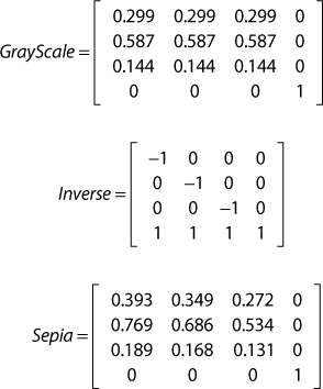
Figure 18.1 shows the output of the grayscale filter applied to a scene with a point light, a reference grid, and a skybox. Note that this demo is fully interactive, just as the original point light demo was. You can relocate the point light in the scene with the number pad keys. The post-processing effect is independent of what was rendered to the off-screen render target.
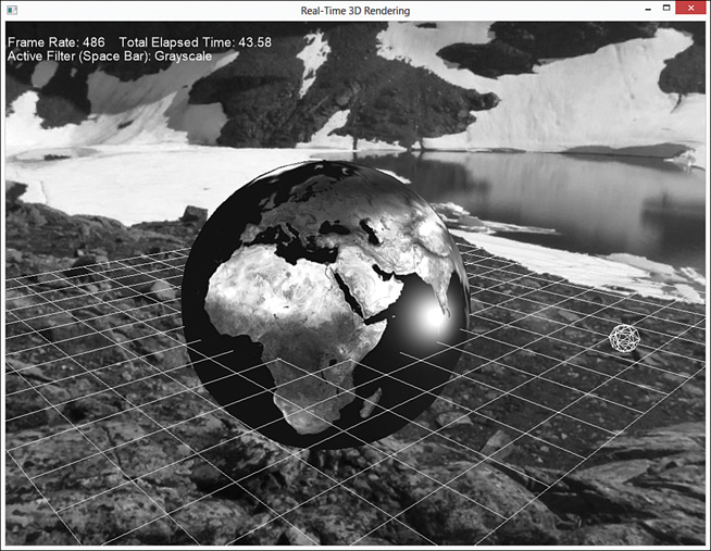
Figure 18.1 Output of the grayscale post-processing effect. (Skybox texture by Emil Persson. Earth texture from Reto Stöckli, NASA Earth Observatory.)
A Color Inverse Filter
You can apply additional color filters with little modification to the code base. For example, you can include a color inverse filter with the following pixel shader and technique:
float4 inverse_pixel_shader(VS_OUTPUT IN) : SV_Target
{
float4 color = ColorTexture.Sample(TrilinearSampler,
IN.TextureCoordinate);
return float4(1 - color.rgb, color.a);
}
technique11 inverse_filter
{
pass p0
{
SetVertexShader(CompileShader(vs_5_0, vertex_shader()));
SetGeometryShader(NULL);
SetPixelShader(CompileShader(ps_5_0, inverse_pixel_shader()));
}
}
This just inverts each color to yield results similar to Figure 18.2.
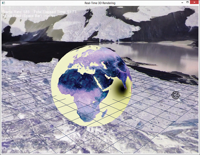
Figure 18.2 Output of the color inverse post-processing effect. (Skybox texture by Emil Persson. Earth texture from Reto Stöckli, NASA Earth Observatory.)
A Sepia Filter
Now let’s create a filter to resemble antique photographs. Back then, black-and-white photographs were actually shades of reddish-brown, called sepia tones. You can create a sepia shader using the same concepts as the grayscale effect, determining the intensity of a pixel through weighted calculations. This time, though, you compute a different intensity for each color channel. The equations are:
You could implement this through three separate dot product operations. But a cleaner alternative is to construct a 3×3 matrix for the sepia coefficients and perform a single matrix multiplication (which is just a set of dot product operations). Listing 18.6 presents the pixel shader and technique for the sepia post-processing effect. You can add this code to the ColorFilter.fx file instead of creating a completely separate effect.
static const float3x3 SepiaFilter = { 0.393f, 0.349f, 0.272f,
0.769f, 0.686f, 0.534f,
0.189f, 0.168f, 0.131f };
float4 sepia_pixel_shader(VS_OUTPUT IN) : SV_Target
{
float4 color = ColorTexture.Sample(TrilinearSampler,
IN.TextureCoordinate);
return float4(mul(color.rgb, SepiaFilter), color.a);
}
technique11 sepia_filter
{
pass p0
{
SetVertexShader(CompileShader(vs_5_0, vertex_shader()));
SetGeometryShader(NULL);
SetPixelShader(CompileShader(ps_5_0, sepia_pixel_shader()));
}
}
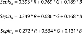
The shader produces output similar to Figure 18.3.
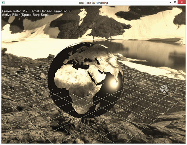
Figure 18.3 Output of the sepia post-processing effect. (Skybox texture by Emil Persson. Earth texture from Reto Stöckli, NASA Earth Observatory.)
A Generic Color Filter
You can extend the implementation of the sepia shader to allow the color filter matrix to be specified at runtime. In this way, you could express all the aforementioned color filters through a single technique. To be as general-purpose as possible, the generic-filter uses a 4×4 color filter matrix. Listing 18.7 presents the listing of the generic filter pixel shader and associated technique.
Listing 18.7 A Generic Color Filter Shader
cbuffer CBufferPerObject
{
float4x4 ColorFilter = { 1, 0, 0, 0,
0, 1, 0, 0,
0, 0, 1, 0,
0, 0, 0, 1 };
}
float4 genericfilter_pixel_shader(VS_OUTPUT IN) : SV_Target
{
float4 color = ColorTexture.Sample(TrilinearSampler,
IN.TextureCoordinate);
return float4(mul(color, ColorFilter).rgb, color.a);
}
technique11 generic_filter
{
pass p0
{
SetVertexShader(CompileShader(vs_5_0, vertex_shader()));
SetGeometryShader(NULL);
SetPixelShader(CompileShader(ps_5_0,
genericfilter_pixel_shader()));
}
}
Using the generic filter shader, you could express the grayscale, inverse, and sepia effects as follows:
The ColorFilteringGame class, found on the companion website, demonstrates the generic color filter using a uniform scaling matrix to simulate brightness (values between 0 and 1 along the diagonal of the color filter matrix). You can increase or decrease the brightness by pressing the comma and period keys, respectively. Moreover, the demo enables you to toggle between the color filters by pressing the spacebar. Note that your ColorFilteringGame::UpdateColorFilterMaterial() callback must be updated to pass in the ColorFilter shader variable. For example:
void ColorFilteringGame::UpdateColorFilterMaterial()
{
XMMATRIX colorFilter = XMLoadFloat4x4(&mGenericColorFilter);
mColorFilterMaterial->ColorTexture() << mRenderTarget->
OutputTexture();
mColorFilterMaterial->ColorFilter() << colorFilter;
}
Figure 18.4 shows the output of the generic color filter simulating a full-screen brightness effect.
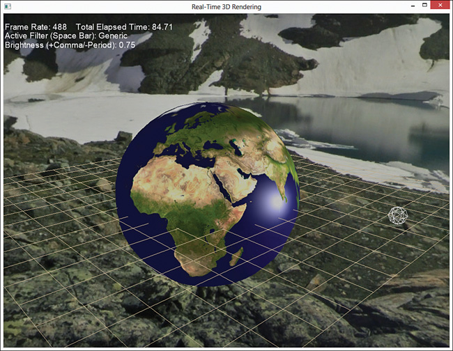
Figure 18.4 Output of the generic color filter shader simulating brightness. (Skybox texture by Emil Persson. Earth texture from Reto Stöckli, NASA Earth Observatory.)
Gaussian Blurring
Color filtering is just one of myriad effects that you can produce with post-processing. Another common technique is to blur the contents of the texture. You can achieve blurring with several approaches; the one presented here is Gaussian blurring, which takes its name from the Gaussian function (also known as the normal distribution) used to blur the image.
To blur an image, the color of each pixel is derived by sampling neighboring pixels. The weighted average of the sampled pixels becomes the color of the pixel in question. You derive the weights for the samples with the Gaussian function:
where, σ is the standard deviation of the Gaussian distribution. Another way to think of σ is that lower values yield a steeper curve, such that only pixels very close to the center (the pixel being computed) have much bearing on the final color. Higher σ values give more weight to neighboring pixels and thereby blur the image more. In the coming implementation, we refer to σ as the blur amount.
Note that the previous equation is expressed in only one dimension, although you’ll be using it to blur a two-dimensional texture. Gaussian blurring is separable, meaning that a two-dimensional blur can be applied as two independent one-dimensional calculations. In practice, this means that you blur the image first horizontally and then vertically.
Drawing with the Gaussian blurring effect can be broken down to the following steps:
1. Draw the scene to an off-screen render target.
2. Blur the scene texture horizontally to an off-screen render target.
3. Vertically blur the horizontally blurred texture and render it to the screen.
A Gaussian Blurring Shader
Listing 18.8 presents the GaussianBlur.fx effect. Its vertex inputs and vertex shader are identical to the ColorFilter.fx effect, but new are the SampleOffsets and SampleWeights arrays. The SampleOffsets array stores the locations of the nearby pixels to sample, relative to the pixel being computed. The SampleWeights array stores the coefficients for each sampled pixel.
Listing 18.8 The GaussianBlur.fx Effect
/************* Resources *************/
#define SAMPLE_COUNT 9
cbuffer CBufferPerFrame
{
float2 SampleOffsets[SAMPLE_COUNT];
float SampleWeights[SAMPLE_COUNT];
}
Texture2D ColorTexture;
SamplerState TrilinearSampler
{
Filter = MIN_MAG_MIP_LINEAR;
AddressU = CLAMP;
AddressV = CLAMP;
};
/************* Data Structures *************/
struct VS_INPUT
{
float4 ObjectPosition : POSITION;
float2 TextureCoordinate : TEXCOORD;
};
struct VS_OUTPUT
{
float4 Position : SV_Position;
float2 TextureCoordinate : TEXCOORD;
};
/************* Vertex Shader *************/
VS_OUTPUT vertex_shader(VS_INPUT IN)
{
VS_OUTPUT OUT = (VS_OUTPUT)0;
OUT.Position = IN.ObjectPosition;
OUT.TextureCoordinate = IN.TextureCoordinate;
return OUT;
}
/************* Pixel Shaders *************/
float4 blur_pixel_shader(VS_OUTPUT IN) : SV_Target
{
float4 color = (float4)0;
for (int i = 0; i < SAMPLE_COUNT; i++)
{
color += ColorTexture.Sample(TrilinearSampler,
IN.TextureCoordinate + SampleOffsets[i]) * SampleWeights[i];
}
return color;
}
float4 no_blur_pixel_shader(VS_OUTPUT IN) : SV_Target
{
return ColorTexture.Sample(TrilinearSampler, IN.TextureCoordinate);
}
/************* Techniques *************/
technique11 blur
{
pass p0
{
SetVertexShader(CompileShader(vs_5_0, vertex_shader()));
SetGeometryShader(NULL);
SetPixelShader(CompileShader(ps_5_0, blur_pixel_shader()));
}
}
technique11 no_blur
{
pass p0
{
SetVertexShader(CompileShader(vs_5_0, vertex_shader()));
SetGeometryShader(NULL);
SetPixelShader(CompileShader(ps_5_0, no_blur_pixel_shader()));
}
}
In this effect, the number of samples is hard-coded to nine, but you can modify the effect to support additional samples or include multiple techniques that pass a uniform sample count to the pixel shader. Generally, you want to surround your pixel with a grid of neighboring pixels, so pick an odd number for the sample count. Understand, however, that the more samples you specify, the more work your pixel shader has to do.
The blur pixel shader iteratively samples the nearby pixels with the offset texture coordinates.
A Gaussian Blurring Component
To integrate the blur shader into your C++ framework, create a GaussianBlur class with a declaration matching Listing 18.9.
Listing 18.9 Declaration of the GaussianBlur Class
class GaussianBlur : public DrawableGameComponent
{
RTTI_DECLARATIONS(GaussianBlur, DrawableGameComponent)
public:
GaussianBlur(Game& game, Camera& camera);
GaussianBlur(Game& game, Camera& camera, float blurAmount);
~GaussianBlur();
ID3D11ShaderResourceView* SceneTexture();
void SetSceneTexture(ID3D11ShaderResourceView& sceneTexture);
ID3D11ShaderResourceView* OutputTexture();
float BlurAmount() const;
void SetBlurAmount(float blurAmount);
virtual void Initialize() override;
virtual void Draw(const GameTime& gameTime) override;
private:
GaussianBlur();
GaussianBlur(const GaussianBlur& rhs);
GaussianBlur& operator=(const GaussianBlur& rhs);
void InitializeSampleWeights();
void InitializeSampleOffsets();
float GetWeight(float x) const;
void UpdateGaussianMaterialWithHorizontalOffsets();
void UpdateGaussianMaterialWithVerticalOffsets();
void UpdateGaussianMaterialNoBlur();
static const float DefaultBlurAmount;
Effect* mEffect;
GaussianBlurMaterial* mMaterial;
ID3D11ShaderResourceView* mSceneTexture;
FullScreenRenderTarget* mHorizontalBlurTarget;
FullScreenQuad* mFullScreenQuad;
std::vector<XMFLOAT2> mHorizontalSampleOffsets;
std::vector<XMFLOAT2> mVerticalSampleOffsets;
std::vector<float> mSampleWeights;
float mBlurAmount;
};
This class has data members for the Gaussian blurring effect, its associated material, and a member for the incoming scene texture (the image to blur). It has a render target for the horizontal blur operation, and its output texture becomes the input texture to the vertical blur pass. All rendering (to the render target or to the screen) is performed using the full-screen quad member.
The horizontal and vertical sample offsets and the sample weights members are populated by the InitializeSampleOffsets() and InitializeSampleWeights() methods. The GetWeight() method implements the Gaussian function to compute a single weight. The three methods whose names begin with “UpdateGaussianMaterial” are the callbacks for updating the full-screen quad material, according to the phase of the blurring process. The Update GaussianMaterialNoBlur() method is used if mBlurAmount is zero. In that scenario, the shader’s no_blur technique is applied to the scene texture, which just presents the unmodified texture to the screen.
You can modify the blur amount at runtime through the SetBlurAmount() method. Recall that the blur amount member is the Gaussian function’s σ and, therefore, the InitializeSampleWeights() method is invoked (to rebuild the sample weights) whenever the blur amount changes. Listing 18.10 presents the methods for initializing the sample offsets and weights.
Listing 18.10 Initializing the Gaussian Blurring Sample Offsets and Weights
void GaussianBlur::InitializeSampleOffsets()
{
float horizontalPixelSize = 1.0f / mGame->ScreenWidth();
float verticalPixelSize = 1.0f / mGame->ScreenHeight();
UINT sampleCount = mMaterial->SampleOffsets().TypeDesc().Elements;
mHorizontalSampleOffsets.resize(sampleCount);
mVerticalSampleOffsets.resize(sampleCount);
mHorizontalSampleOffsets[0] = Vector2Helper::Zero;
mVerticalSampleOffsets[0] = Vector2Helper::Zero;
for (UINT i = 0; i < sampleCount / 2; i++)
{
float sampleOffset = i * 2 + 1.5f;
float horizontalOffset = horizontalPixelSize * sampleOffset;
float verticalOffset = verticalPixelSize * sampleOffset;
mHorizontalSampleOffsets[i * 2 + 1] =
XMFLOAT2(horizontalOffset, 0.0f);
mHorizontalSampleOffsets[i * 2 + 2] = XMFLOAT2
(-horizontalOffset, 0.0f);
mVerticalSampleOffsets[i * 2 + 1] = XMFLOAT2
(0.0f, verticalOffset);
mVerticalSampleOffsets[i * 2 + 2] = XMFLOAT2
(0.0f, -verticalOffset);
}
}
void GaussianBlur::InitializeSampleWeights()
{
UINT sampleCount = mMaterial->SampleOffsets().TypeDesc().Elements;
mSampleWeights.resize(sampleCount);
mSampleWeights[0] = GetWeight(0);
float totalWeight = mSampleWeights[0];
for (UINT i = 0; i < sampleCount / 2; i++)
{
float weight = GetWeight((float)i + 1);
mSampleWeights[i * 2 + 1] = weight;
mSampleWeights[i * 2 + 2] = weight;
totalWeight += weight * 2;
}
// Normalize the weights so that they sum to one
for (UINT i = 0; i < mSampleWeights.size(); i++)
{
mSampleWeights[i] /= totalWeight;
}
}
float GaussianBlur::GetWeight(float x) const
{
return (float)(exp(-(x * x) / (2 * mBlurAmount * mBlurAmount)));
}
The InitializeSampleOffsets() method builds up the vertical and horizontal offsets around the center pixel (at index 0), based on the current resolution of your application. The InitializeSampleWeights() method assigns weights to the corresponding indices and then normalizes them so that they sum to 1. If the weights weren’t normalized, they would increase (sum greater than 1) or decrease (sum less than 1) the brightness of the final image.
Listing 18.11 presents the GaussianBlur::Draw() method.
Listing 18.11 Drawing the Gaussian Blurring Component
void GaussianBlur::Draw(const GameTime& gameTime)
{
if (mBlurAmount > 0.0f)
{
// Horizontal blur
mHorizontalBlurTarget->Begin();
mGame->Direct3DDeviceContext()->ClearRenderTargetView(mHorizontalBlurTarget->RenderTargetView() , reinterpret_cast<const
float*>(&ColorHelper::Purple));
mGame->Direct3DDeviceContext()->ClearDepthStencilView
(mHorizontalBlurTarget->DepthStencilView(), D3D11_CLEAR_DEPTH | D3D11_
CLEAR_STENCIL, 1.0f, 0);
mFullScreenQuad->SetActiveTechnique("blur", "p0");
mFullScreenQuad->SetCustomUpdateMaterial(std::bind
(&GaussianBlur::UpdateGaussianMaterialWithHorizontalOffsets, this));
mFullScreenQuad->Draw(gameTime);
mHorizontalBlurTarget->End();
// Vertical blur for the final image
mFullScreenQuad->SetCustomUpdateMaterial(std::bind
(&GaussianBlur::UpdateGaussianMaterialWithVerticalOffsets, this));
mFullScreenQuad->Draw(gameTime);
}
else
{
mFullScreenQuad->SetActiveTechnique("no_blur", "p0");
mFullScreenQuad->SetCustomUpdateMaterial(std::bind
(&GaussianBlur::UpdateGaussianMaterialNoBlur, this));
mFullScreenQuad->Draw(gameTime);
}
}
void GaussianBlur::UpdateGaussianMaterialWithHorizontalOffsets()
{
mMaterial->ColorTexture() << mSceneTexture;
mMaterial->SampleWeights() << mSampleWeights;
mMaterial->SampleOffsets() << mHorizontalSampleOffsets;
}
void GaussianBlur::UpdateGaussianMaterialWithVerticalOffsets()
{
mMaterial->ColorTexture() <<
mHorizontalBlurTarget->OutputTexture();
mMaterial->SampleWeights() << mSampleWeights;
mMaterial->SampleOffsets() << mVerticalSampleOffsets;
}
void GaussianBlur::UpdateGaussianMaterialNoBlur()
{
mMaterial->ColorTexture() << mSceneTexture;
}
If mBlurAmount is greater than 0, the blur technique is set for the full-screen quad member and the blur process is performed. The horizontal blur render target is bound to the output-merger stage, its views are cleared, and the quad is drawn using the UpdateGaussianMaterialWithHorizontalOffsets() callback. This callback passes in the scene texture, the sample weights, and the horizontal sample offsets. After completing the draw, the back buffer is restored to the output-merger stage.
Next, the quad is drawn again, but this time using the UpdateGaussianMaterialWithVerticalOffsets() callback. This method passes the output texture of the horizontal blur render target, the sample weights, and the vertical sample offsets. Because the back buffer is bound to the output-merger stage, the results of this draw are presented when the swap chain is flipped.
To integrate this component with your Game-derived class, initialize the component with code such as this:
mGaussianBlur = new GaussianBlur(*this, *mCamera);
mGaussianBlur->SetSceneTexture(*(mRenderTarget->OutputTexture()));
mGaussianBlur->Initialize();
Here, mRenderTarget is used to render the scene. Following is the principal content within the GaussianBlurGame::Draw() method used for the demonstration application. You can find the full application on the companion website.
mRenderTarget->Begin();
mDirect3DDeviceContext->ClearRenderTargetView(mRenderTarget->
RenderTargetView() , reinterpret_cast<const float*>(&BackgroundColor));
mDirect3DDeviceContext->ClearDepthStencilView(mRenderTarget->
DepthStencilView(), D3D11_CLEAR_DEPTH | D3D11_CLEAR_STENCIL, 1.0f, 0);
Game::Draw(gameTime);
mRenderTarget->End();
mDirect3DDeviceContext->ClearRenderTargetView(mRenderTargetView,
reinterpret_cast<const float*>(&BackgroundColor));
mDirect3DDeviceContext->ClearDepthStencilView(mDepthStencilView, D3D11_
CLEAR_DEPTH | D3D11_CLEAR_STENCIL, 1.0f, 0);
mGaussianBlur->Draw(gameTime);
Figure 18.5 shows the output of the Gaussian blurring demo with a blur amount of 3.0.
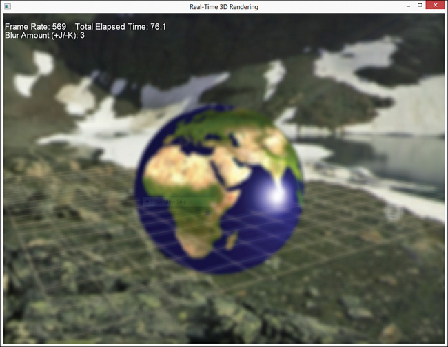
Figure 18.5 Output of the Gaussian blurring effect. (Skybox texture by Emil Persson. Earth texture from Reto Stöckli, NASA Earth Observatory.)
Bloom
The Gaussian blurring effect has a variety of applications. For example, you could use it to distinguish background (blurred to appear out of focus) and foreground (unblurred) objects. Another use is with a bloom (or glow) effect. A bloom effect exaggerates bright areas of the scene to simulate a real-world camera. Figure 18.6 shows a scene with bloom (top image) and without bloom.
Figure 18.6 A scene rendered with (top) and without (bottom) a bloom effect. (Skybox texture by Emil Persson. Earth texture from Reto Stöckli, NASA Earth Observatory.)
You can create the bloom effect using the following steps:
1. Draw the scene to an off-screen render target.
2. Extract the bright spots from the scene image to an off-screen render target (create a glow map).
3. Blur the glow map to an off-screen render target.
4. Combine the blurred glow map with the original scene texture, and render it to the screen.
Listing 18.12 presents the Bloom.fx effect. It includes three separate techniques: one to extract the bright areas of an input texture to create a glow map, another to combine a blurred glow map with the original scene, and a third to render the original scene unmodified. The Gaussian blurring shader is not replicated in this effect because you reuse the previously authored GaussianBlur component to blur the extracted glow map.
Listing 18.12 The Bloom.fx Effect
/************* Resources *************/
static const float3 GrayScaleIntensity = { 0.299f, 0.587f, 0.114f };
Texture2D ColorTexture;
Texture2D BloomTexture;
cbuffer CBufferPerObject
{
float BloomThreshold = 0.45f;
float BloomIntensity = 1.25f;
float BloomSaturation = 1.0f;
float SceneIntensity = 1.0f;
float SceneSaturation = 1.0f;
};
SamplerState TrilinearSampler
{
Filter = MIN_MAG_MIP_LINEAR;
AddressU = WRAP;
AddressV = WRAP;
};
/************* Data Structures *************/
struct VS_INPUT
{
float4 Position : POSITION;
float2 TextureCoordinate : TEXCOORD;
};
struct VS_OUTPUT
{
float4 Position : SV_Position;
float2 TextureCoordinate : TEXCOORD;
};
/************* Utility Functions *************/
float4 AdjustSaturation(float4 color, float saturation)
{
float intensity = dot(color.rgb, GrayScaleIntensity);
return float4(lerp(intensity.rrr, color.rgb, saturation), color.a);
}
/************* Vertex Shader *************/
VS_OUTPUT vertex_shader(VS_INPUT IN)
{
VS_OUTPUT OUT = (VS_OUTPUT)0;
OUT.Position = IN.Position;
OUT.TextureCoordinate = IN.TextureCoordinate;
return OUT;
}
/************* Pixel Shaders *************/
float4 bloom_extract_pixel_shader(VS_OUTPUT IN) : SV_Target
{
float4 color = ColorTexture.Sample(TrilinearSampler,
IN.TextureCoordinate);
return saturate((color - BloomThreshold) / (1 - BloomThreshold));
}
float4 bloom_composite_pixel_shader(VS_OUTPUT IN) : SV_Target
{
float4 sceneColor = ColorTexture.Sample(TrilinearSampler,
IN.TextureCoordinate);
float4 bloomColor = BloomTexture.Sample(TrilinearSampler,
IN.TextureCoordinate);
sceneColor = AdjustSaturation(sceneColor, SceneSaturation) *
SceneIntensity;
bloomColor = AdjustSaturation(bloomColor, BloomSaturation) *
BloomIntensity;
sceneColor *= (1 - saturate(bloomColor));
return sceneColor + bloomColor;
}
float4 no_bloom_pixel_shader(VS_OUTPUT IN) : SV_Target
{
return ColorTexture.Sample(TrilinearSampler, IN.TextureCoordinate);
}
/************* Techniques *************/
technique11 bloom_extract
{
pass p0
{
SetVertexShader(CompileShader(vs_5_0, vertex_shader()));
SetGeometryShader(NULL);
SetPixelShader(CompileShader(ps_5_0,
bloom_extract_pixel_shader()));
}
}
technique11 bloom_composite
{
pass p0
{
SetVertexShader(CompileShader(vs_5_0, vertex_shader()));
SetGeometryShader(NULL);
SetPixelShader(CompileShader(ps_5_0,
bloom_composite_pixel_shader()));
}
}
technique11 no_bloom
{
pass p0
{
SetVertexShader(CompileShader(vs_5_0, vertex_shader()));
SetGeometryShader(NULL);
SetPixelShader(CompileShader(ps_5_0, no_bloom_pixel_shader()));
}
}
The bloom_extract_pixel_shader compares the sampled color to a passed-in threshold. If the color is less than the threshold, the output pixel is black. The color is further modulated by the inverse of the threshold. This isn’t the only way you might create a glow map: An alternative is to use the intensity of the sampled texture in comparison with the bloom threshold. For example:
float4 bloom_extract_pixel_shader(VS_OUTPUT IN) : SV_Target
{
float4 color = ColorTexture.Sample(TrilinearSampler,
IN.TextureCoordinate);
float intensity = dot(color.rgb, GrayScaleIntensity);
return (intensity > BloomThreshold ? color : float4(0, 0, 0, 1));
}
Figure 18.7 shows a glow map extracted from a scene using both of these pixel shaders.
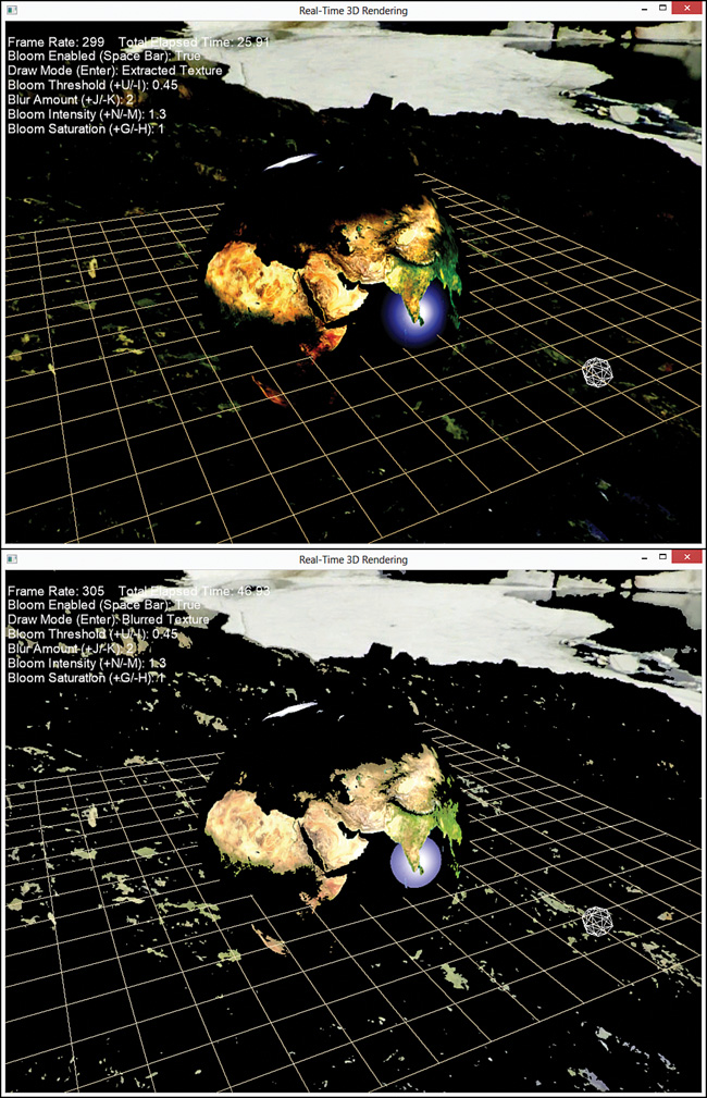
Figure 18.7 Glow maps extracted from a scene using the original method (top) and an alternate method (bottom). (Skybox texture by Emil Persson. Earth texture from Reto Stöckli, NASA Earth Observatory.)
The glow map is blurred by the Gaussian blurring component to give the glow a “bleed over” effect as the light intrudes into other pixels. This blurred glow map is combined with the original scene texture, but you can further modulate it with intensity and saturation values. The demo application on the companion website enables you to interact with these values. Experimentation will produce some interesting results.
Distortion Mapping
The final post-processing technique we cover in this chapter is distortion mapping. Distortion mapping is akin to the displacement mapping effect in Chapter 9, “Normal Mapping and Displacement Mapping.” But where displacement mapping alters an object’s vertices, distortion mapping alters its pixels. More specifically, you sample a texture (a distortion map) for horizontal and vertical offsets and apply these offsets to the UV for lookup into the scene texture.
A Full-Screen Distortion Shader
Listing 18.13 presents the pixel shader for a full-screen post-processing distortion effect.
Listing 18.13 A Full-Screen Distortion Mapping Pixel Shader
cbuffer CBufferPerObject
{
float DisplacementScale = 1.0f;
}
Texture2D SceneTexture;
Texture2D DistortionMap;
SamplerState TrilinearSampler
{
Filter = MIN_MAG_MIP_LINEAR;
AddressU = CLAMP;
AddressV = CLAMP;
};
float4 displacement_pixel_shader(VS_OUTPUT IN) : SV_Target
{
float4 OUT = (float4)0;
float2 displacement = DistortionMap.Sample(TrilinearSampler, IN.TextureCoordinate).xy - 0.5;
OUT = SceneTexture.Sample(TrilinearSampler, IN.TextureCoordinate + (DisplacementScale * displacement));
return OUT;
}
This shader samples two channels (x and y) for horizontal and vertical displacement. These are 8-bit channels mapped from [0, 255] to floating point values [0.0, 1.0]. However, the pixel displacement can be positive or negative, so you must scale the range. The specific scale depends on how your displacement maps are created, but this example scales the range to [-0.5, 0.5]. From an artist’s perspective, that means that the channel value 127 yields (almost) no displacement. I say almost because 127 / 255 ≈ 0.49804, so there’s an error of 0.5 – 0.49804 = .00196. You can compensate for this error by adding this value into the displacement calculation. For example:
static const float ZeroCorrection = 0.5f / 255.0f;
float2 displacement = DistortionMap.Sample(TrilinearSampler, IN.TextureCoordinate).xy - 0.5 + ZeroCorrection;
Rendering with this shader is normal post-processing—identical to the color filtering shaders. You render your scene to an off-screen render target and then render a full-screen quad to the back buffer using the distortion mapping shader. Figure 18.8 shows the output of the displacement shader using a distortion map made to look like warped glass.
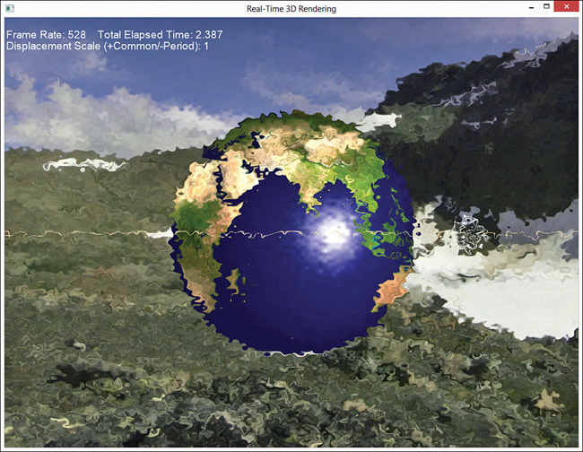
Figure 18.8 Output of the full-screen distortion mapping shader using a distortion map resembling warped glass. (Skybox texture by Emil Persson. Earth texture from Reto Stöckli, NASA Earth Observatory.)
The variation in the warped glass distortion map is so subtle that you wouldn’t be able to easily distinguish the perturbations (even with a magnified image). Thus, Figure 18.9 shows the output of the displacement shader (top) using a distortion map (bottom) containing the text “Direct3D !”. Notice the yellowish appearance of the distortion map; this is because only the red and green channels are populated.
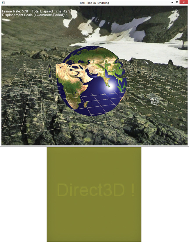
Figure 18.9 Output of the full-screen distortion mapping shader (top) and associated distortion map (bottom). (Skybox texture by Emil Persson. Earth texture from Reto Stöckli, NASA Earth Observatory.)
A Masking Distortion Shader
The full-screen distortion mapping shader can produce some interesting effects—even more interesting if you animate the displacement offsets (accomplished by modulating the offsets by some continuously changing value, such as time). However, you might not want to distort the entire scene. For example, you could simulate the heat haze above a fire (or hot pavement) and want to isolate the effect to that specific location.
One way to accomplish this is to create a run-time distortion mask, a full-screen distortion map with a cutout of the area you want to be distorted. Figure 18.10 shows a distortion mask created using the warped glass distortion map and a sphere.
This distortion mask is created with an off-screen render target by first clearing the target to black pixels and then rendering objects onto the target. However, instead of rendering colors from an object’s color texture, you look up offsets from a distortion map. Thus, the created distortion mask is made up of either black pixels or distortion offsets. After the mask is created, you perform a post-processing pass between the scene texture and the distortion mask. In this step, you first sample from the distortion mask. If its value is black, you sample the scene texture without displacing its UV. Otherwise, you displace the UV with the offsets sampled from the mask. Listing 18.14 presents the complete source code for this effect.
Listing 18.14 A Masking Distortion Mapping Effect
/************* Resources *************/
static const float ZeroCorrection = 0.5f / 255.0f;
cbuffer CBufferPerObjectCutout
{
float4x4 WorldViewProjection : WORLDVIEWPROJECTION;
}
cbuffer CBufferPerObjectComposite
{
float DisplacementScale = 1.0f;
}
Texture2D SceneTexture;
Texture2D DistortionMap;
SamplerState TrilinearSampler
{
Filter = MIN_MAG_MIP_LINEAR;
AddressU = WRAP;
AddressV = WRAP;
};
/************* Data Structures *************/
struct VS_INPUT
{
float4 Position : POSITION;
float2 TextureCoordinate : TEXCOORD;
};
struct VS_OUTPUT
{
float4 Position : SV_Position;
float2 TextureCoordinate : TEXCOORD;
};
/************* Cutout *************/
VS_OUTPUT distortion_cutout_vertex_shader(VS_INPUT IN)
{
VS_OUTPUT OUT = (VS_OUTPUT)0;
OUT.Position = mul(IN.Position, WorldViewProjection);
OUT.TextureCoordinate = IN.TextureCoordinate;
return OUT;
}
float4 distortion_cutout_pixel_shader(VS_OUTPUT IN) : SV_Target
{
float2 displacement = DistortionMap.Sample(TrilinearSampler, IN.TextureCoordinate).xy;
return float4(displacement.xy, 0, 1);
}
/************* Distortion Post Processing *************/
VS_OUTPUT distortion_vertex_shader(VS_INPUT IN)
{
VS_OUTPUT OUT = (VS_OUTPUT)0;
OUT.Position = IN.Position;
OUT.TextureCoordinate = IN.TextureCoordinate;
return OUT;
}
float4 distortion_pixel_shader(VS_OUTPUT IN) : SV_Target
{
float4 OUT = (float4)0;
float2 displacement = DistortionMap.Sample(TrilinearSampler, IN.TextureCoordinate).xy;
if (displacement.x == 0 && displacement.y == 0)
{
OUT = SceneTexture.Sample(TrilinearSampler,
IN.TextureCoordinate);
}
else
{
displacement -= 0.5f + ZeroCorrection;
OUT = SceneTexture.Sample(TrilinearSampler,
IN.TextureCoordinate + (DisplacementScale * displacement));
}
return OUT;
}
float4 no_distortion_pixel_shader(VS_OUTPUT IN) : SV_Target
{
return SceneTexture.Sample(TrilinearSampler, IN.TextureCoordinate);
}
/************* Techniques *************/
technique11 distortion_cutout
{
pass p0
{
SetVertexShader(CompileShader(vs_5_0,
distortion_cutout_vertex_shader()));
SetGeometryShader(NULL);
SetPixelShader(CompileShader(ps_5_0,
distortion_cutout_pixel_shader()));
}
}
technique11 distortion
{
pass p0
{
SetVertexShader(CompileShader(vs_5_0,
distortion_vertex_shader()));
SetGeometryShader(NULL);
SetPixelShader(CompileShader(ps_5_0,
distortion_pixel_shader()));
}
}
technique11 no_distortion
{
pass p0
{
SetVertexShader(CompileShader(vs_5_0,
distortion_composite_vertex_shader()));
SetGeometryShader(NULL);
SetPixelShader(CompileShader(ps_5_0,
no_distortion_pixel_shader()));
}
}
This shader uses three techniques:
![]() distortion_cutout: References vertex and pixel shaders for creating the distortion mask. The vertex shader expects the incoming vertex positions to be in object space and, therefore, transforms them. The pixel shader outputs the
distortion_cutout: References vertex and pixel shaders for creating the distortion mask. The vertex shader expects the incoming vertex positions to be in object space and, therefore, transforms them. The pixel shader outputs the x and y channels from the distortion map using the regular texture coordinates of the vertices.
![]() distortion: Defines the post-processing step between the scene texture and the distortion mask. The vertex shader expects the incoming vertex positions to be in screen space and does not transform them (as with all the post-processing effects). The pixel shader outputs the sampled scene texture either with or without a displacement offset, depending on the values of the offsets.
distortion: Defines the post-processing step between the scene texture and the distortion mask. The vertex shader expects the incoming vertex positions to be in screen space and does not transform them (as with all the post-processing effects). The pixel shader outputs the sampled scene texture either with or without a displacement offset, depending on the values of the offsets.
![]() no_distortion: Outputs the scene texture with no distortion.
no_distortion: Outputs the scene texture with no distortion.
Rendering the masking distortion shader requires two render targets, one to render the un-distorted background objects and one to create the distortion mask. You can find a full demonstration application on the companion website. Figure 18.11 shows the output of the masking distortion shader (top) using a model of a humanoid torso to create the distortion mask (bottom).
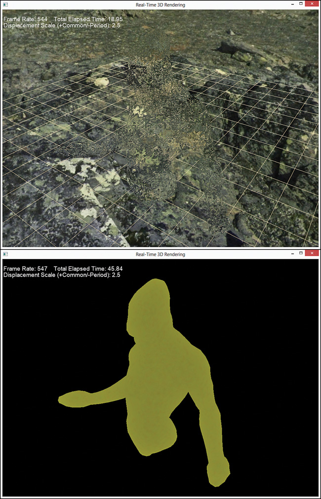
Figure 18.11 Output of the distortion masking shader (top) and associated distortion mask (bottom). (Skybox texture by Emil Persson. 3D model by Nick Zuccarello, Florida Interactive Entertainment Academy.)
Summary
This chapter introduced the topic of post-processing, graphics techniques applied after the scene is rendered. You authored a number of post-processing effects for color filtering, Gaussian blurring, bloom/glow, and distortion mapping. You integrated these effects into your C++ rendering framework with full-screen render target and quad components, and you explored demonstration applications to exercise these effects.
In the next chapter, you learn techniques for projective texture mapping and shadow mapping.
Exercises
1. Experiment with all the effects and demo applications from this chapter. Vary the shader inputs, and observe the results.
2. Create your own distortion maps for the post-processing distortion shader, and use them with the associated demo application.
3. Animate the masking distortion shader to simulate heat haze above a fire. Hint: Use GameTime::TotalGameTime() as input into the shader.