
Chapter 9. Normal Mapping and Displacement Mapping
In this chapter, you discover techniques for adding detail to your scenes without necessarily increasing the poly count of your objects. With normal mapping, you create “fake” geometry for simulating light interaction. And with displacement mapping, you create bumps and recesses by actually moving vertices according to texture data.
Normal Mapping
In previous chapters, you learned about specular maps, environment maps, and transparency maps—textures that provide additional information to your shaders. Specular maps limit the specular highlight, environment maps contribute colors for reflective surfaces, and transparency maps control alpha blending in the output-merger stage. This information is provided per pixel, a much higher resolution than if the data were supplied per vertex. Similarly, a normal map provides surface normals per pixel, and this extra data has many applications.
One application of normal maps is to fake the detail of a bumpy surface, such as a stone wall. You could model such a wall with geometry for actual bumps and recesses—and the more vertices you used, the greater detail you would achieve. This geometry would respond well to lights in the scene, showing dark areas where the stone faced away from the light. However, added geometry comes at a cost. Instead, it’s possible to create a low-poly object (even a flat plane) and use a normal map to simulate the lighting effects that would be present if the added geometry were there. This application is called normal mapping.
Normal Maps
Figure 9.1 shows a color map (left) and normal map (right) for a stone wall. Note the relatively odd look of the normal map. Although you visualize a normal map in color, what’s stored are 3D directions vectors. When you sample the normal map, the results you find in the RGB channels are the x, y, and z components of the direction. You can use these normals in calculating, for example, the diffuse lighting term.

Figure 9.1 A color map (left) and normal map (right) for a stone wall. (Textures by Nick Zuccarello, Florida Interactive Entertainment Academy.)
The channels of an RGB texture store unsigned 8-bit values and, therefore, have a range of [0, 255]. But the xyz components of a normalized direction vector have a range of [-1, 1]. Consequently, the normals must be shifted for storage in the texture and shifted back when the vector is sampled. You transform the floating-point vector from [-1, 1] to [0, 255] using the following function:
f(x) = (0.5x + 0.5) * 255
And you transform it back with the function:
In practice, you use an image-manipulation tool such as Adobe Photoshop to encode a normal map in RGB texture format. But you’re responsible for shifting the value back into the range [-1, 1] when you sample the texture from within your shader. The floating-point division (by 255) is done for you during the sampling process so that the sampled values will exist in the range [0, 1]. Therefore, you only need to shift the sampled vector with this function:
f(x) = 2x − 1
Alternately, you can use 16- or 32-bit floating-point texture formats for your normal maps, which yields better results at the expense of performance.
Tangent Space
You can use a per-pixel normal to compute the diffuse term, just as you would with a per-vertex normal. However, the normal must be in the same coordinate space as your light. For per-vertex normals, the data is provided in object space. But for normal maps, the data is provided in tangent space.
Tangent space (or texture space) is a coordinate system with respect to the texture and is described by three orthogonal vectors: the surface normal, tangent, and binormal. Figure 9.2 illustrates these vectors.

Figure 9.2 An illustration of tangent space. (Texture by Nick Zuccarello, Florida Interactive Entertainment Academy.)
The normal vector, N, is the regular surface normal of a vertex. The tangent vector, T, is orthogonal to the surface normal and is in the direction of the u-axis of the texture. The binormal, B, runs along the texture’s v-axis.
You can use these three vectors to construct a tangent, binormal, normal (TBN) transformation matrix, as follows:

You can use this matrix to transform vectors from tangent space to object space. However, because the light vector is (commonly) in world space, you need to transform the sampled normal from tangent space to world space. You can do this by transforming the normal from tangent space to object space and then to world space. Alternatively, you can build the TBN matrix from vectors that are already in world space.
You can encode normals directly in world space, which removes the need for transformation. However, then the objects that used those normals would need to remain static (no transformation). Furthermore, world space–encoded normals couldn’t be easily reused between objects (again, because they can’t be transformed).
An interesting property of the TBN matrix is that it is made from orthonormal vectors (orthogonal unit vectors) and therefore forms a basis set (it defines a coordinate system). Moreover, the inverse of this matrix is its transpose. Thus, to transform a vector from object or world space back into tangent space (inverse mapping), you can just multiply the vector by the transpose of the TBN matrix. Additionally, the orthonormal property of the TBN matrix implies that, if you have two of the vectors, you can derive the third. The normal and tangent vectors are commonly stored alongside the geometry, with the binormal computed (within the vertex shader) as a cross product between these two vectors. Performing such computation is often a desirable tradeoff between added GPU computation and the high cost of data transfer between the CPU and GPU.
A Normal Mapping Effect
With that bit of terminology in hand, Listing 9.1 presents the code for a normal mapping effect.
#include "include\Common.fxh"
cbuffer CBufferPerFrame
{
float4 AmbientColor : AMBIENT <
string UIName = "Ambient Light";
string UIWidget = "Color";
> = {1.0f, 1.0f, 1.0f, 1.0f};
float4 LightColor : COLOR <
string Object = "LightColor0";
string UIName = "Light Color";
string UIWidget = "Color";
> = {1.0f, 1.0f, 1.0f, 1.0f};
float3 LightDirection : DIRECTION <
string Object = "DirectionalLight0";
string UIName = "Light Direction";
string Space = "World";
> = {0.0f, 0.0f, -1.0f};
float3 CameraPosition : CAMERAPOSITION < string UIWidget="None"; >;
}
cbuffer CBufferPerObject
{
float4x4 WorldViewProjection : WORLDVIEWPROJECTION < string
UIWidget="None"; >;
float4x4 World : WORLD < string UIWidget="None"; >;
float4 SpecularColor : SPECULAR <
string UIName = "Specular Color";
string UIWidget = "Color";
> = {1.0f, 1.0f, 1.0f, 1.0f};
float SpecularPower : SPECULARPOWER <
string UIName = "Specular Power";
string UIWidget = "slider";
float UIMin = 1.0;
float UIMax = 255.0;
float UIStep = 1.0;
> = {25.0f};
}
Texture2D ColorTexture <
string ResourceName = "default_color.dds";
string UIName = "Color Texture";
string ResourceType = "2D";
>;
Texture2D NormalMap <
string ResourceName = "default_bump_normal.dds";
string UIName = "Normap Map";
string ResourceType = "2D";
>;
SamplerState TrilinearSampler
{
Filter = MIN_MAG_MIP_LINEAR;
AddressU = WRAP;
AddressV = WRAP;
};
RasterizerState DisableCulling
{
CullMode = NONE;
};
/************* Data Structures *************/
struct VS_INPUT
{
float4 ObjectPosition : POSITION;
float2 TextureCoordinate : TEXCOORD;
float3 Normal : NORMAL;
float3 Tangent : TANGENT;
};
struct VS_OUTPUT
{
float4 Position : SV_Position;
float3 Normal : NORMAL;
float3 Tangent : TANGENT;
float3 Binormal : BINORMAL;
float2 TextureCoordinate : TEXCOORD0;
float3 LightDirection : TEXCOORD1;
float3 ViewDirection : TEXCOORD2;
};
/************* Vertex Shader *************/
VS_OUTPUT vertex_shader(VS_INPUT IN)
{
VS_OUTPUT OUT = (VS_OUTPUT)0;
OUT.Position = mul(IN.ObjectPosition, WorldViewProjection);
OUT.Normal = normalize(mul(float4(IN.Normal, 0), World).xyz);
OUT.Tangent = normalize(mul(float4(IN.Tangent, 0), World).xyz);
OUT.Binormal = cross(OUT.Normal, OUT.Tangent);
OUT.TextureCoordinate = get_corrected_texture_coordinate(IN.
TextureCoordinate);
OUT.LightDirection = normalize(-LightDirection);
float3 worldPosition = mul(IN.ObjectPosition, World).xyz;
float3 viewDirection = CameraPosition - worldPosition;
OUT.ViewDirection = normalize(viewDirection);
return OUT;
}
/************* Pixel Shader *************/
float4 pixel_shader(VS_OUTPUT IN) : SV_Target
{
float4 OUT = (float4)0;
float3 sampledNormal = (2 * NormalMap.Sample(TrilinearSampler,
IN.TextureCoordinate).xyz) - 1.0; // Map normal from [0..1] to [-1..1]
float3x3 tbn = float3x3(IN.Tangent, IN.Binormal, IN.Normal);
sampledNormal = mul(sampledNormal, tbn); // Transform normal to
world space
float3 viewDirection = normalize(IN.ViewDirection);
float4 color = ColorTexture.Sample(TrilinearSampler,
IN.TextureCoordinate);
float3 ambient = get_vector_color_contribution(AmbientColor, color.
rgb);
LIGHT_CONTRIBUTION_DATA lightContributionData;
lightContributionData.Color = color;
lightContributionData.Normal = sampledNormal;
lightContributionData.ViewDirection = viewDirection;
lightContributionData.LightDirection = float4(IN.LightDirection, 1);
lightContributionData.SpecularColor = SpecularColor;
lightContributionData.SpecularPower = SpecularPower;
lightContributionData.LightColor = LightColor;
float3 light_contribution = get_light_contribution
(lightContributionData);
OUT.rgb = ambient + light_contribution;
OUT.a = 1.0f;
return OUT;
}
/************* Techniques *************/
technique10 main10
{
pass p0
{
SetVertexShader(CompileShader(vs_4_0, vertex_shader()));
SetGeometryShader(NULL);
SetPixelShader(CompileShader(ps_4_0, pixel_shader()));
SetRasterizerState(DisableCulling);
}
}
Normal Mapping Preamble
The preamble for this effect employs an ambient light, specular highlight, and a single directional light. A new Texture2D object exists for the normal map, and the VS_INPUT struct accepts a tangent (in object space) along with the surface normal. The VS_OUTPUT struct has new members for the tangent and binormal, which will be transformed to world space before they are passed.
Normal Mapping Vertex and Pixel Shader
The vertex shader transforms the normal and tangent into world space and then performs a cross product between the vectors to produce the binormal. The pixel shader samples the normal map and shifts the sampled normal from [0, 1] to [-1, 1]. Then it builds the TBN matrix and uses it to transform the sampled normal into world space. When the normal is in world space, the remaining lighting calculations are the same as with previous effects.
Note
If you find that your vertex shader is a performance bottleneck, you can provide the binormal as input (alongside the surface normal and tangent). It’s a tradeoff between the performance of the vertex shader and the data passed over the graphics bus. More commonly, the graphics bus is the bottleneck.
Normal Mapping Output
Figure 9.3 shows the results of the normal mapping effect applied to a plane with a stone wall texture. The normal map from Figure 9.1 is used for the left-side image. For the image to the right, a normal map is applied that contains no perturbations. For both images, the ambient light is disabled, the directional light is pure white at full intensity, and the specular highlight has a power of 100 with an intensity of 0.35.
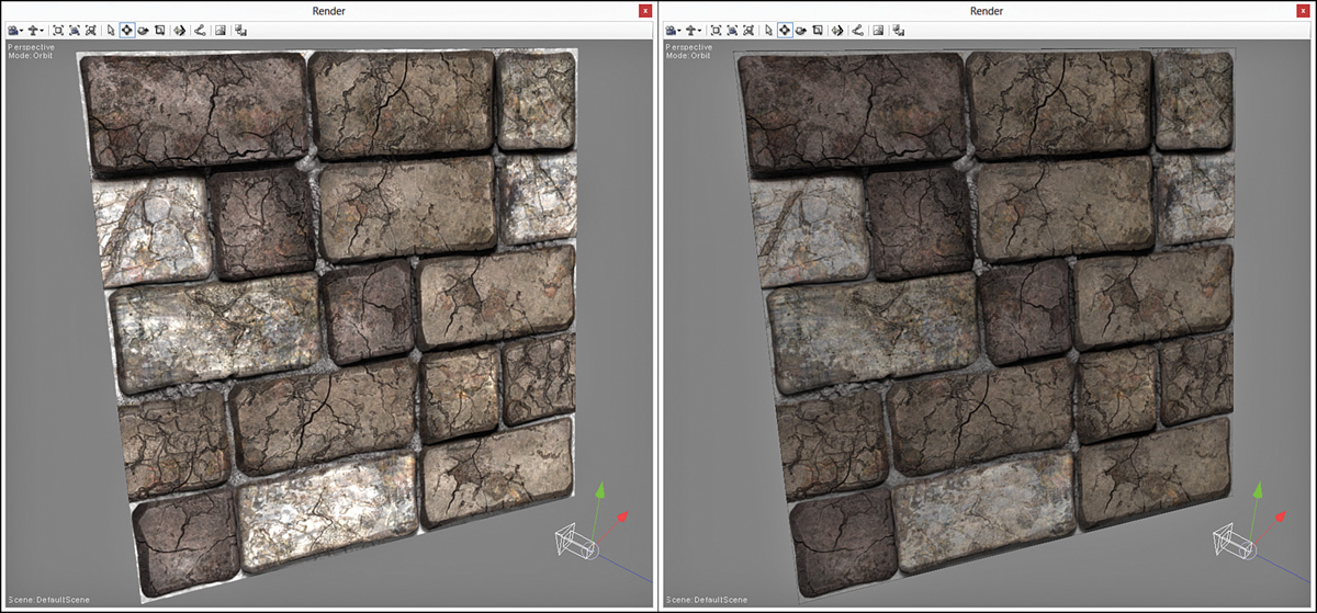
Figure 9.3 NormalMapping.fx applied to a plane with a stone wall texture using a normal map (left) and without a normal map (right). (Textures by Nick Zuccarello, Florida Interactive Entertainment Academy.)
Displacement Mapping
Another application of normal maps is displacement mapping, in which detail is added not by faking lighting, but by actually perturbing the vertices of a model. With displacement mapping, a vertex is translated along its normal by an amount specified in a displacement map. A displacement map is just a height map, a single-channel texture that stores magnitudes. Figure 9.4 shows a displacement map for the stone wall texture used throughout this chapter. Because the displacement map has just a single 8-bit channel, it’s visualized in grayscale.

Figure 9.4 A color map (left) and displacement map (right) for a stone wall. (Textures by Nick Zuccarello, Florida Interactive Entertainment Academy.)
When displacing a vertex, you do so either inward or outward along its normal, with the magnitude sampled from the displacement map. For outward displacement, you use the following equation:
Position = Position0 + (Normal * Scale * DisplacementMagnitude)
Here, Scale is a shader constant that scales the magnitudes stored within the displacement map. For inward displacement, the equation is rewritten as:
Position = Position0 + (Normal * Scale * DisplacementMagnitude − 1)
A Displacement Mapping Effect
Listing 9.2 presents the code for an abbreviated displacement mapping effect. This listing displays only the code specific to displacement mapping within the vertex shader.
Listing 9.2 An Abbreviated Displacement Mapping Effect
cbuffer CBufferPerObject
{
/* ... */
float DisplacementScale <
string UIName = "Displacement Scale";
string UIWidget = "slider";
float UIMin = 0.0;
float UIMax = 2.0;
float UIStep = 0.01;
> = {0.0f};
}
Texture2D DisplacementMap <
string UIName = "Displacement Map";
string ResourceType = "2D";
>;
VS_OUTPUT vertex_shader(VS_INPUT IN)
{
VS_OUTPUT OUT = (VS_OUTPUT)0;
float2 textureCoordinate = get_corrected_texture_coordinate(IN.
TextureCoordinate);
if (DisplacementScale > 0.0f)
{
float displacement = DisplacementMap.
SampleLevel(TrilinearSampler, textureCoordinate, 0);
IN.ObjectPosition.xyz += IN.Normal * DisplacementScale *
(displacement - 1);
}
OUT.Position = mul(IN.ObjectPosition, WorldViewProjection);
OUT.TextureCoordinate = textureCoordinate;
OUT.Normal = normalize(mul(float4(IN.Normal, 0), World).xyz);
float3 worldPosition = normalize(mul(IN.ObjectPosition, World)).
xyz;
OUT.ViewDirection = normalize(CameraPosition - worldPosition);
OUT.LightDirection = get_light_data(LightPosition, worldPosition,
LightRadius);
return OUT;
}
Displacement Mapping Preamble
The CBufferPerFrame block contains a new member for displacement scale. A new Texture2D object also exists for the displacement map. You can combine these new members with any of the lighting effects you’ve developed thus far.
Displacement Mapping Vertex Shader
The displacement mapping-specific code samples the displacement magnitude and then displaces the vertex inward along its normal. When sampling a texture from within the vertex shader, you use the SampleLevel() method, where the second parameter is the mip-level. Note that the normal mapping code has been removed from Listing 9.2, to point out that the normal is not coming from a separate texture. A better iteration of this effect is to employ tessellation to add vertices and sample the normal from a normal map. Part IV “Intermediate-Level Rendering Topics,” explores this topic further.
Displacement Mapping Output
Figure 9.5 shows the results of the displacement mapping effect applied to a plane with the stone wall texture. In the image to the left, the displacement map in Figure 9.4 is applied with a scale of 0.2. For the image to the right, the displacement is nullified with a scale of 0.0.

Figure 9.5 DisplacementMapping.fx applied to a plane with a stone wall texture using a displacement map (left) and without a displacement map (right). (Textures by Nick Zuccarello, Florida Interactive Entertainment Academy.)
The plane used in Figure 9.5 was created using Autodesk Maya, with 50 horizontal and vertical subdivisions. It has a higher vertex count than the built-in plane model NVIDIA FX Composer includes.
Summary
In this chapter, you learned about normal mapping and displacement mapping, techniques for adding detail to an object without necessarily increasing geometry. This chapter marks the end of Part II, “Shader Authoring with HLSL.” In the next section, you begin working with the DirectX API using C++ and incorporate the shaders you’ve authored into a C++ rendering engine.
Exercises
1. Find or create a color texture with an associated normal map (resource links are available on the book’s companion website). Use these textures to experiment with the normal mapping effect. Modify the lighting, manipulate the camera, and observe the output.
2. Implement a complete displacement mapping effect that incorporates a single point light.
3. Find or create a color texture with an associated displacement map. Use these textures to experiment with the displacement mapping effect. Modify the displacement scale, and observe the results.