
Chapter 19. Shadow Mapping
In this chapter, you learn how to render shadows. You learn about depth maps (2D textures that store depths instead of colors) and projective texture mapping (think the Batman signal). You also examine common problems with rendering shadows and determine how to address them.
Motivation
Shadows are part of our visual experience, but unless you’re making shadow puppets, you don’t likely even notice the myriad shadows that surround you. Remove them, however, and something will feel off. That’s a conundrum for video games and simulations because realistic shadows are difficult to produce and computationally expensive. They are subtle and almost unconsciously perceived, but leave them out, and your users will notice that something about the scene is just not quite right. In this chapter, we discuss shadow mapping, a common technique for producing shadows. Along the way, we introduce projective texture mapping, a technique for projecting a 2D texture onto arbitrary geometry. We also discuss the various shortcomings of projective texture mapping and shadow mapping, and explore ways to overcome them.
Projective Texture Mapping
Shadow mapping involves producing a depth map, a 2D texture that stores the depths of objects nearest the light source, and mapping that texture onto the geometry you want to accept a shadow (the shadow’s receiver). Thus, a first step to understanding shadow mapping is to discuss projective texture mapping. Projective texture mapping is analogous to a slide or movie projector. The projector is defined by a frustum, in the same way as a virtual camera, and is used to generate texture coordinates to sample the projected image.
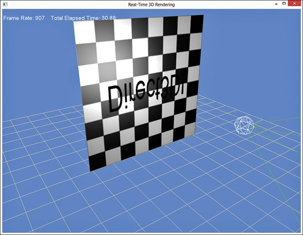
Figure 19.1 shows the output of a projective texture mapping shader with a texture of the text “Direct3D!” projected onto a plane colored with a checkerboard pattern. The green lines depict the frustum of the projector, and the white sphere represents a point light in the scene.
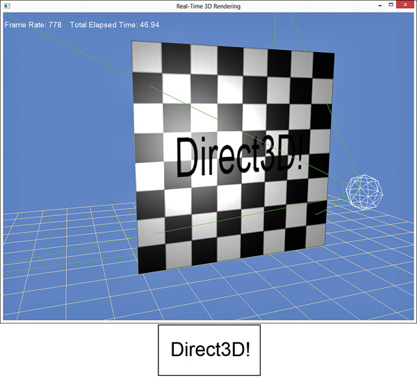
Figure 19.1 Output of the projective texture mapping shader (top) with the projected texture (bottom).
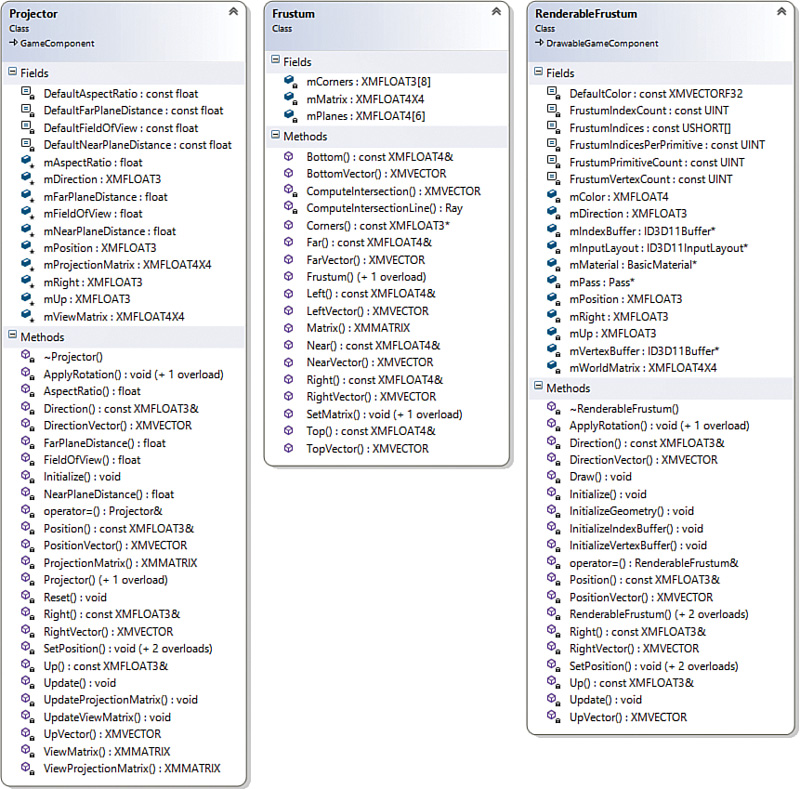
Three helper classes are used for projective texture mapping: Projector, Frustum, and RenderableFrustum; see Figure 19.2 for the class diagrams. We do not list these classes here, but you can find the full source code on the companion website.
Projective Texture Coordinates
The Projector class is nearly identical to the Camera class, and its output is the ViewProjection matrix. This matrix transforms an object into projection space from the perspective of the projector instead of from the perspective of the camera. You can use the transformed position (the x and y components) as the lookup into the projected texture. However, the coordinates will be in normalized device coordinate space (NDC space, or screen space) whose range is [-1, 1], and a texture is mapped with a range [0, 1]. Therefore, you must scale the projective texture coordinates as follows:
v = −0.5y + 0.5
These equations can be composed in matrix form as:
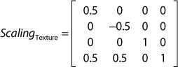
If you concatenate the object’s world matrix, the projector’s view and projection matrices, and the texture scaling matrix, you can transform an object from local space to projective texture space with a single matrix multiplication. We call this construct a projective texture matrix.
A Projective Texture-Mapping Shader
Listing 19.1 presents a shader for projective texture mapping. It uses the point light shader as its foundation, with variables for a single point light, ambient light, and specular highlights. New are variables for the ProjectiveTextureMatrix and the ProjectedTexture.
Listing 19.1 An Initial Projective Texture-Mapping Shader
#include "include\Common.fxh"
/************* Resources *************/
static const float4 ColorWhite = { 1, 1, 1, 1 };
cbuffer CBufferPerFrame
{
float4 AmbientColor = { 1.0f, 1.0f, 1.0f, 0.0f };
float4 LightColor = { 1.0f, 1.0f, 1.0f, 1.0f };
float3 LightPosition = { 0.0f, 0.0f, 0.0f };
float LightRadius = 10.0f;
float3 CameraPosition;
}
cbuffer CBufferPerObject
{
float4x4 WorldViewProjection : WORLDVIEWPROJECTION;
float4x4 World : WORLD;
float4 SpecularColor : SPECULAR = { 1.0f, 1.0f, 1.0f, 1.0f };
float SpecularPower : SPECULARPOWER = 25.0f;
float4x4 ProjectiveTextureMatrix;
}
Texture2D ColorTexture;
Texture2D ProjectedTexture;
SamplerState ProjectedTextureSampler
{
Filter = MIN_MAG_MIP_LINEAR;
AddressU = BORDER;
AddressV = BORDER;
BorderColor = ColorWhite;
};
SamplerState ColorSampler
{
Filter = MIN_MAG_MIP_LINEAR;
AddressU = WRAP;
AddressV = WRAP;
};
RasterizerState BackFaceCulling
{
CullMode = BACK;
};
/************* Data Structures *************/
struct VS_INPUT
{
float4 ObjectPosition : POSITION;
float2 TextureCoordinate : TEXCOORD;
float3 Normal : NORMAL;
};
struct VS_OUTPUT
{
float4 Position : SV_Position;
float3 Normal : NORMAL;
float2 TextureCoordinate : TEXCOORD0;
float3 WorldPosition : TEXCOORD1;
float Attenuation : TEXCOORD2;
float4 ProjectedTextureCoordinate : TEXCOORD3;
};
/************* Vertex Shader *************/
VS_OUTPUT project_texture_vertex_shader(VS_INPUT IN)
{
VS_OUTPUT OUT = (VS_OUTPUT)0;
OUT.Position = mul(IN.ObjectPosition, WorldViewProjection);
OUT.WorldPosition = mul(IN.ObjectPosition, World).xyz;
OUT.TextureCoordinate = IN.TextureCoordinate;
OUT.Normal = normalize(mul(float4(IN.Normal, 0), World).xyz);
float3 lightDirection = LightPosition - OUT.WorldPosition;
OUT.Attenuation = saturate(1.0f - (length(lightDirection) /
LightRadius));
OUT.ProjectedTextureCoordinate = mul(IN.ObjectPosition, ProjectiveTextureMatrix);
return OUT;
}
/************* Pixel Shaders *************/
float4 project_texture_pixel_shader(VS_OUTPUT IN) : SV_Target
{
float4 OUT = (float4)0;
float3 lightDirection = LightPosition - IN.WorldPosition;
lightDirection = normalize(lightDirection);
float3 viewDirection = normalize(CameraPosition
-IN.WorldPosition);
float3 normal = normalize(IN.Normal);
float n_dot_l = dot(normal, lightDirection);
float3 halfVector = normalize(lightDirection + viewDirection);
float n_dot_h = dot(normal, halfVector);
float4 color = ColorTexture.Sample(ColorSampler,
IN.TextureCoordinate);
float4 lightCoefficients = lit(n_dot_l, n_dot_h, SpecularPower);
float3 ambient = get_vector_color_contribution(AmbientColor,
color.rgb);
float3 diffuse = get_vector_color_contribution(LightColor,
lightCoefficients.y * color.rgb) * IN.Attenuation;
float3 specular = get_scalar_color_contribution(SpecularColor,
min(lightCoefficients.z, color.w)) * IN.Attenuation;
OUT.rgb = ambient + diffuse + specular;
OUT.a = 1.0f;
IN.ProjectedTextureCoordinate.xy /= IN.ProjectedTextureCoordinate.w;
float3 projectedColor = ProjectedTexture.
Sample(ProjectedTextureSampler, IN.ProjectedTextureCoordinate.xy).rgb;
OUT.rgb *= projectedColor;
return OUT;
}
/************* Techniques *************/
technique11 project_texture
{
pass p0
{
SetVertexShader(CompileShader(vs_5_0,
project_texture_vertex_shader()));
SetGeometryShader(NULL);
SetPixelShader(CompileShader(ps_5_0,
project_texture_pixel_shader()));
SetRasterizerState(BackFaceCulling);
}
}
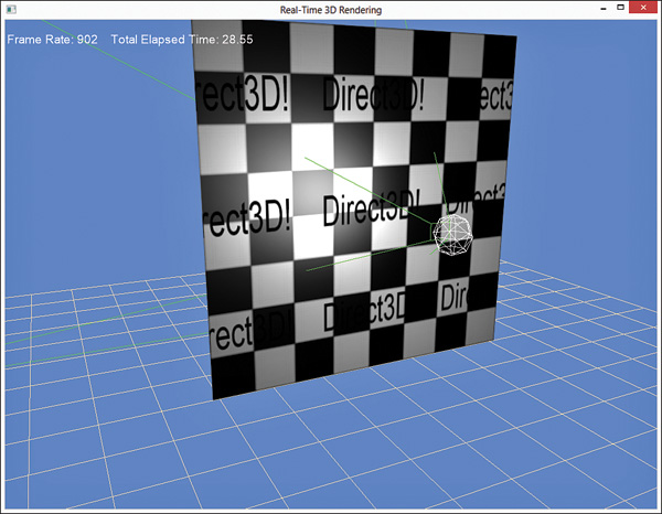
The vertex shader has only one line that is specific to projective texture mapping: the transformation of the vertex from local space into projective texture space. The resulting vector is stored in the VS_OUTPUT.ProjectedTextureCoordinate member for pass-through to the pixel shader. The pixel shader divides the x and y components of this vector by its w component to transform the position into NDC space. This step is called the homogeneous divide or perspective divide, and it is performed automatically for the position passed using the SV_POSITION semantic. After this final transformation, the projected texture can be sampled and applied to the final color. Note the ProjectedTextureSampler object that’s used for sampling the projected texture. It specifies trilinear filtering and a texture addressing mode of BORDER with a white border color. Projective texture coordinates can extend beyond the range of [0, 1], and a white border provides the multiplicative identity for any such coordinates. You aren’t limited to using border addressing mode and should experiment. Figure 19.3 shows the output of the shader when wrapping texture addresses.
Reverse Projection
We must address a few issues with the shader in Listing 19.1. The first is that the projector appears to emit from either side of the frustum to create a reverse projection. Figure 19.4 shows this effect.
To correct this, verify that the projected texture coordinate’s w component is greater than or equal to 0. For example:
if (IN.ProjectedTextureCoordinate.w >= 0.0f)
{
IN.ProjectedTextureCoordinate.xy /= IN.ProjectedTextureCoordinate.w;
float3 projectedColor = ProjectedTexture.
Sample(ProjectedTextureSampler, IN.ProjectedTextureCoordinate.xy).rgb;
OUT.rgb *= projectedColor;
}
In the demo on the companion website, this is implemented in a separate pixel shader and technique. In this way, you need not branch if reverse projection isn’t a concern.
Occlusion
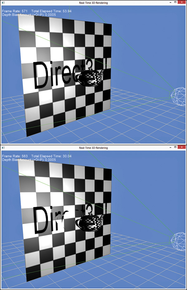
A second problem is that the shader in Listing 19.1 doesn’t address objects that occlude other objects (or themselves). Consider the images in Figure 19.5. Both images include a teapot placed in front of the plane, and each object is rendered with the same projected texture. In the top image, the texture is incorrectly projected onto the plane for areas that would otherwise be occluded by the teapot. In the bottom image, a depth map has been created for the scene and used for occlusion testing. Such occlusion testing applies not only to the plane, but also to the teapot. For instance, if the teapot was rotated so that the handle was occluded by the pot (with respect to the projector), the handle would not (incorrectly) receive the projected texture.
Creating a Depth Map
You create a depth map (a texture that stores distances from the projector or light source, instead of colors) using the render-to-target feature discussed in the last chapter. Listing 19.2 presents the declaration of the DepthMap class, which encapsulates the functionality required for building a depth map.
Listing 19.2 Declaration of the DepthMap Class
class DepthMap : public RenderTarget
{
RTTI_DECLARATIONS(DepthMap, RenderTarget)
public:
DepthMap(Game& game, UINT width, UINT height);
~DepthMap();
ID3D11ShaderResourceView* OutputTexture() const;
ID3D11DepthStencilView* DepthStencilView() const;
virtual void Begin() override;
virtual void End() override;
private:
DepthMap();
DepthMap(const DepthMap& rhs);
DepthMap& operator=(const DepthMap& rhs);
Game* mGame;
ID3D11DepthStencilView* mDepthStencilView;
ID3D11ShaderResourceView* mOutputTexture;
D3D11_VIEWPORT mViewport;
};
The DepthMap class contains members and accessors for a depth-stencil view and a shader resource view, but not for a render target view. Unlike the render-to-target work from the last chapter, you need not create a depth map through a pixel shader/render target view. Your depth map can be generated through the vertex shader with a depth-stencil view, and you can disable the pixel shader stage (which has a positive performance impact) by setting the render target view to NULL. The DepthMap class also contains a member for a viewport, which has the same dimensions as the depth map. This enables you to create a depth map that is smaller than your game’s resolution, thereby reducing memory overhead and improving performance. Listing 19.3 presents the implementation of the DepthMap class.
Listing 19.3 Implementation of the DepthMap Class
#include "DepthMap.h"
#include "Game.h"
#include "GameException.h"
namespace Library
{
RTTI_DEFINITIONS(DepthMap)
DepthMap::DepthMap(Game& game, UINT width, UINT height)
: RenderTarget(), mGame(&game), mDepthStencilView(nullptr),
mOutputTexture(nullptr), mViewport()
{
D3D11_TEXTURE2D_DESC textureDesc;
ZeroMemory(&textureDesc, sizeof(textureDesc));
textureDesc.Width = width;
textureDesc.Height = height;
textureDesc.MipLevels = 1;
textureDesc.ArraySize = 1;
textureDesc.Format = DXGI_FORMAT_R24G8_TYPELESS;
textureDesc.SampleDesc.Count = 1;
textureDesc.BindFlags = D3D11_BIND_DEPTH_STENCIL| D3D11_BIND_SHADER_RESOURCE;
HRESULT hr;
ID3D11Texture2D* texture = nullptr;
if (FAILED(hr = game.Direct3DDevice()->CreateTexture2D
(&textureDesc, nullptr, &texture)))
{
throw GameException("IDXGIDevice::CreateTexture2D()
failed.", hr);
}
D3D11_SHADER_RESOURCE_VIEW_DESC resourceViewDesc;
ZeroMemory(&resourceViewDesc, sizeof(resourceViewDesc));
resourceViewDesc.Format = DXGI_FORMAT_R24_UNORM_X8_TYPELESS;
resourceViewDesc.ViewDimension = D3D_SRV_DIMENSION_TEXTURE2D;
resourceViewDesc.Texture2D.MipLevels = 1;
if (FAILED(hr = game.Direct3DDevice()
->CreateShaderResourceView(texture, &resourceViewDesc,
&mOutputTexture)))
{
ReleaseObject(texture);
throw GameException("IDXGIDevice::CreateShaderResource
View() failed.", hr);
}
D3D11_DEPTH_STENCIL_VIEW_DESC depthStencilViewDesc;
ZeroMemory(&depthStencilViewDesc, sizeof
(depthStencilViewDesc));
depthStencilViewDesc.Format = DXGI_FORMAT_D24_UNORM_S8_UINT;
depthStencilViewDesc.ViewDimension =
D3D11_DSV_DIMENSION_TEXTURE2D;
depthStencilViewDesc.Texture2D.MipSlice = 0;
if (FAILED(hr = game.Direct3DDevice()->CreateDepthStencilView
(texture, &depthStencilViewDesc, &mDepthStencilView)))
{
ReleaseObject(texture);
throw GameException("IDXGIDevice::CreateDepthStencilView()
failed.", hr);
}
ReleaseObject(texture);
mViewport.TopLeftX = 0.0f;
mViewport.TopLeftY = 0.0f;
mViewport.Width = static_cast<float>(width);
mViewport.Height = static_cast<float>(height);
mViewport.MinDepth = 0.0f;
mViewport.MaxDepth = 1.0f;
}
DepthMap::~DepthMap()
{
ReleaseObject(mOutputTexture);
ReleaseObject(mDepthStencilView);
}
ID3D11ShaderResourceView* DepthMap::OutputTexture() const
{
return mOutputTexture;
}
ID3D11DepthStencilView* DepthMap::DepthStencilView() const
{
return mDepthStencilView;
}
void DepthMap::Begin()
{
static ID3D11RenderTargetView* nullRenderTargetView = nullptr;
RenderTarget::Begin(mGame->Direct3DDeviceContext(), 1,
&nullRenderTargetView, mDepthStencilView, mViewport);
}
void DepthMap::End()
{
RenderTarget::End(mGame->Direct3DDeviceContext());
}
}
Most of this implementation resides within the DepthMap constructor. First, a 2D texture is created to store the actual depth map data. Note the DXGI_FORMAT_R24G8_TYPELESS format specified for the texture. This indicates that the texture will be split into 24-bit and 8-bit components. The TYPELESS identifier denotes that the depth-stencil and the shader resource views will treat the texture differently. The depth-stencil view is bound to the output-merger stage, and the shader resource view is supplied as input into a shader (the projective texture mapping shader, for example). After the shader resource and depth-stencil views are created, the texture object can be released (because the two views maintain references to the object). Finally, a viewport is created.
The DepthMap::Begin() and DepthMap::End() methods perform the same function as their counterparts in the FullScreenRenderTarget class from the last chapter: They bind the depth-stencil view to the output-merger stage and restore the previous render targets, respectively. However, these methods now invoke members from a base RenderTarget class that implements a render target stack. RenderTarget::Begin() pushes the specified render targets onto the stack before binding them to the output-merger stage, and vice versa for RenderTarget::End(). This allows nested render-targets. Listings 19.4 and 19.5 present the declaration and implementation of the RenderTarget base class.
Listing 19.4 Declaration of the RenderTarget Class
class RenderTarget : public RTTI
{
RTTI_DECLARATIONS(RenderTarget, RTTI)
public:
RenderTarget();
virtual ~RenderTarget();
virtual void Begin() = 0;
virtual void End() = 0;
protected:
typedef struct _RenderTargetData
{
UINT ViewCount;
ID3D11RenderTargetView** RenderTargetViews;
ID3D11DepthStencilView* DepthStencilView;
D3D11_VIEWPORT Viewport;
_RenderTargetData(UINT viewCount, ID3D11RenderTargetView** renderTargetViews, ID3D11DepthStencilView* depthStencilView, const D3D11_VIEWPORT& viewport)
: ViewCount(viewCount), RenderTargetViews(renderTarget
Views), DepthStencilView(depthStencilView), Viewport(viewport) { }
} RenderTargetData;
void Begin(ID3D11DeviceContext* deviceContext, UINT viewCount,
ID3D11RenderTargetView** renderTargetViews, ID3D11DepthStencilView*
depthStencilView, const D3D11_VIEWPORT& viewport);
void End(ID3D11DeviceContext* deviceContext);
private:
RenderTarget(const RenderTarget& rhs);
RenderTarget& operator=(const RenderTarget& rhs);
static std::stack<RenderTargetData> sRenderTargetStack;
};
Listing 19.5 Implementation of the RenderTarget Class
#include "RenderTarget.h"
#include "Game.h"
namespace Library
{
RTTI_DEFINITIONS(RenderTarget)
std::stack<RenderTarget::RenderTargetData> RenderTarget::
sRenderTargetStack;
RenderTarget::RenderTarget()
{
}
RenderTarget::~RenderTarget()
{
}
void RenderTarget::Begin(ID3D11DeviceContext* deviceContext,
UINT viewCount, ID3D11RenderTargetView** renderTargetViews,
ID3D11DepthStencilView* depthStencilView, const D3D11_VIEWPORT&
viewport)
{
sRenderTargetStack.push(RenderTargetData(viewCount,
renderTargetViews, depthStencilView, viewport));
deviceContext->OMSetRenderTargets(viewCount, renderTargetViews,
depthStencilView);
deviceContext->RSSetViewports(1, &viewport);
}
void RenderTarget::End(ID3D11DeviceContext* deviceContext)
{
sRenderTargetStack.pop();
if (sRenderTargetStack.size() > 0)
{
RenderTargetData renderTargetData = sRenderTargetStack.
top();
deviceContext->OMSetRenderTargets(renderTargetData.
ViewCount, renderTargetData.RenderTargetViews, renderTargetData.
DepthStencilView);
deviceContext->RSSetViewports(1, &renderTargetData.
Viewport);
}
else
{
static ID3D11RenderTargetView* nullRenderTargetView =
nullptr;
deviceContext->OMSetRenderTargets(1, &nullRenderTargetView,
nullptr);
}
}
}
Note that, with the introduction of the RenderTarget class, the base Game class becomes a RenderTarget. You can find the updated source code on the companion website.
Using the DepthMap class is simple: You merely bind the depth map to the output-merger stage and render the scene (or a portion of the scene) from the perspective of the projector. For example:
mDepthMap->Begin();
ID3D11DeviceContext* direct3DDeviceContext =
mGame->Direct3DDeviceContext();
direct3DDeviceContext->IASetPrimitiveTopology(D3D11_PRIMITIVE_TOPOLOGY_
TRIANGLELIST);
direct3DDeviceContext->ClearDepthStencilView(mDepthMap
->DepthStencilView(), D3D11_CLEAR_DEPTH | D3D11_CLEAR_STENCIL, 1.0f, 0);
Pass* pass = mDepthMapMaterial->CurrentTechnique()->Passes().at(0);
ID3D11InputLayout* inputLayout = mDepthMapMaterial->InputLayouts().
at(pass);
direct3DDeviceContext->IASetInputLayout(inputLayout);
UINT stride = mDepthMapMaterial->VertexSize();
UINT offset = 0;
direct3DDeviceContext->IASetVertexBuffers(0, 1,
&mModelPositionVertexBuffer, &stride, &offset);
direct3DDeviceContext->IASetIndexBuffer(mModelIndexBuffer, DXGI_FORMAT_
R32_UINT, 0);
XMMATRIX modelWorldMatrix = XMLoadFloat4x4(&mModelWorldMatrix);
mDepthMapMaterial->WorldLightViewProjection() << modelWorldMatrix *
mProjector->ViewMatrix() * mProjector->ProjectionMatrix();
pass->Apply(0, direct3DDeviceContext);
direct3DDeviceContext->DrawIndexed(mModelIndexCount, 0, 0);
mDepthMap->End();
The DepthMapMaterial class, referenced in the previous code snippet, supports the Depth shader in Listing 19.6.
Map.fx
Listing 19.6 The DepthMap.fx Shader
cbuffer CBufferPerObject
{
float4x4 WorldLightViewProjection;
}
float4 create_depthmap_vertex_shader(float4 ObjectPosition : POSITION)
: SV_Position
{
return mul(ObjectPosition, WorldLightViewProjection);
}
technique11 create_depthmap
{
pass p0
{
SetVertexShader(CompileShader(vs_5_0,
create_depthmap_vertex_shader()));
SetGeometryShader(NULL);
SetPixelShader(NULL);
}
}
This effect has only a single variable, WorldLightViewProjection, and accepts just an ObjectPosition as input to the vertex shader. Also notice how the create_depthmap technique sets the pixel shader to NULL.
A Projective Texture-Mapping Shader with Occlusion Testing
With the capability to create a depth map, you can now update the projective texture mapping shader to support occlusion testing. Listing 19.7 presents the updated shader, abbreviated for brevity.
Listing 19.7 An Updated Projective Texture-Mapping Shader with Occlusion Testing
cbuffer CBufferPerFrame
{
/* ... */
float DepthBias = 0.005;
}
Texture2D ColorTexture;
Texture2D ProjectedTexture;
Texture2D DepthMap;
SamplerState DepthMapSampler
{
Filter = MIN_MAG_MIP_POINT;
AddressU = BORDER;
AddressV = BORDER;
BorderColor = ColorWhite;
};
float4 project_texture_w_depthmap_pixel_shader(VS_OUTPUT IN) :
SV_Target
{
float4 OUT = (float4)0;
float3 lightDirection = LightPosition - IN.WorldPosition;
lightDirection = normalize(lightDirection);
float3 viewDirection = normalize(CameraPosition
- IN.WorldPosition);
float3 normal = normalize(IN.Normal);
float n_dot_l = dot(normal, lightDirection);
float3 halfVector = normalize(lightDirection + viewDirection);
float n_dot_h = dot(normal, halfVector);
float4 color = ColorTexture.Sample(ColorSampler,
IN.TextureCoordinate);
float4 lightCoefficients = lit(n_dot_l, n_dot_h, SpecularPower);
float3 ambient = get_vector_color_contribution(AmbientColor, color.
rgb);
float3 diffuse = get_vector_color_contribution(LightColor,
lightCoefficients.y * color.rgb) * IN.Attenuation;
float3 specular = get_scalar_color_contribution(SpecularColor,
min(lightCoefficients.z, color.w)) * IN.Attenuation;
OUT.rgb = ambient + diffuse + specular;
OUT.a = 1.0f;
if (IN.ProjectedTextureCoordinate.w >= 0.0f)
{
IN.ProjectedTextureCoordinate.xyz /= IN.ProjectedTexture
Coordinate.w;
float pixelDepth = IN.ProjectedTextureCoordinate.z;
float sampledDepth = DepthMap.Sample(DepthMapSampler,
IN.ProjectedTextureCoordinate.xy).x + DepthBias;
float3 projectedColor = (pixelDepth > sampledDepth ?
ColorWhite : ProjectedTexture.Sample(ProjectedTextureSampler,
IN.ProjectedTextureCoordinate.xy).rgb);
OUT.rgb *= projectedColor;
}
return OUT;
}
/************* Techniques *************/
technique11 project_texture_w_depthmap
{
pass p0
{
SetVertexShader(CompileShader(vs_5_0,
project_texture_vertex_shader()));
SetGeometryShader(NULL);
SetPixelShader(CompileShader(ps_5_0,
project_texture_w_depthmap_pixel_shader()));
SetRasterizerState(BackFaceCulling);
}
}
The shader now includes variables for the DepthMap and a DepthBias (described shorty), along with a DepthMapSampler. Unlike the projected texture (which uses trilinear filtering to reduce rendering artifacts), the depth map sampler uses point filtering to find the nearest depth value to the requested UV. A texel in the depth map represents a specific location in the scene. Although you can sample multiple depths and interpolate the notion of which of them is occluding an object and which is not (which you do in the next section), you should not interpolate the depth itself.
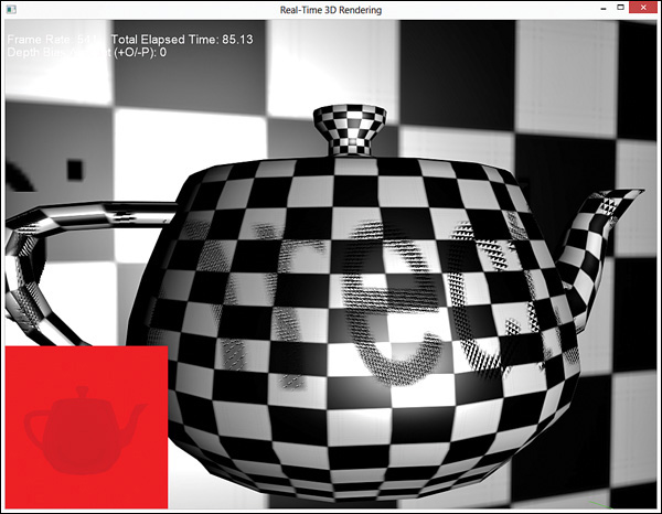
Examine the pixel shader and notice that the homogeneous divide is performed on the x, y, and z components of the ProjectedTextureCoordinate input member. The z component represents the pixel depth of the rendered object from the perspective of the projector. This value is compared against the sampled depth to determine whether the projected texture should be applied to the final color. If the pixel depth is greater than the sampled depth, an object is occluding the pixel from the perspective of the projector. Notice that the DepthBias variable modifies the sampled depth. This is a first peek at a problem you’ll encounter when implementing shadow mapping: shadow acne. You can see this in Figure 19.6, where the shader is supplied with a DepthBias of 0. (Figure 19.6 also shows the depth map in the lower-left corner.)
Shadow acne is an error with self-shadowing that occurs because the shadow map is limited in its resolution and its depths are quantized. When comparing the actual depth against the sampled depth, the results vary. Thus, some of the pixels indicate that they should receive the projected texture, and some do not. Precision errors can also cause shadow acne. A simple fix is to bias the depth by some fixed amount. Or instead of using a fixed-depth bias, you might employ slope-scaled depth biasing, a technique presented in the discussion of shadow mapping.
Another approach to eliminating shadow acne is to cull front-facing geometry when rendering the depth map.
Shadow Mapping
You now have all the pieces necessary to implement shadow mapping. Indeed, shadow mapping follows practically the same process as projective texture mapping with occlusion testing. First, you render the scene to a depth map from the perspective of a light. Next, you render the scene from the perspective of the camera, using the depth map as input to determine whether an object is “in shadow.” Listing 19.8 presents a first pass at a shadow-mapping shader.
Listing 19.8 An initial shadow-mapping shader
#include "include\Common.fxh"
/************* Resources *************/
static const float4 ColorWhite = { 1, 1, 1, 1 };
static const float3 ColorBlack = { 0, 0, 0 };
static const float DepthBias = 0.005;
cbuffer CBufferPerFrame
{
float4 AmbientColor = { 1.0f, 1.0f, 1.0f, 0.0f };
float4 LightColor = { 1.0f, 1.0f, 1.0f, 1.0f };
float3 LightPosition = { 0.0f, 0.0f, 0.0f };
float LightRadius = 10.0f;
float3 CameraPosition;
}
cbuffer CBufferPerObject
{
float4x4 WorldViewProjection : WORLDVIEWPROJECTION;
float4x4 World : WORLD;
float4 SpecularColor : SPECULAR = { 1.0f, 1.0f, 1.0f, 1.0f };
float SpecularPower : SPECULARPOWER = 25.0f;
float4x4 ProjectiveTextureMatrix;
}
Texture2D ColorTexture;
Texture2D ShadowMap;
SamplerState ShadowMapSampler
{
Filter = MIN_MAG_MIP_POINT;
AddressU = BORDER;
AddressV = BORDER;
BorderColor = ColorWhite;
};
SamplerState ColorSampler
{
Filter = MIN_MAG_MIP_LINEAR;
AddressU = WRAP;
AddressV = WRAP;
};
RasterizerState BackFaceCulling
{
CullMode = BACK;
};
/************* Data Structures *************/
struct VS_INPUT
{
float4 ObjectPosition : POSITION;
float2 TextureCoordinate : TEXCOORD;
float3 Normal : NORMAL;
};
struct VS_OUTPUT
{
float4 Position : SV_Position;
float3 Normal : NORMAL;
float2 TextureCoordinate : TEXCOORD0;
float3 WorldPosition : TEXCOORD1;
float Attenuation : TEXCOORD2;
float4 ShadowTextureCoordinate : TEXCOORD3;
};
/************* Vertex Shader *************/
VS_OUTPUT vertex_shader(VS_INPUT IN)
{
VS_OUTPUT OUT = (VS_OUTPUT)0;
OUT.Position = mul(IN.ObjectPosition, WorldViewProjection);
OUT.WorldPosition = mul(IN.ObjectPosition, World).xyz;
OUT.TextureCoordinate = IN.TextureCoordinate;
OUT.Normal = normalize(mul(float4(IN.Normal, 0), World).xyz);
float3 lightDirection = LightPosition - OUT.WorldPosition;
OUT.Attenuation = saturate(1.0f - (length(lightDirection) / LightRadius));
OUT.ShadowTextureCoordinate = mul(IN.ObjectPosition,
ProjectiveTextureMatrix);
return OUT;
}
/************* Pixel Shader *************/
float4 shadow_pixel_shader(VS_OUTPUT IN) : SV_Target
{
float4 OUT = (float4)0;
float3 lightDirection = LightPosition - IN.WorldPosition;
lightDirection = normalize(lightDirection);
float3 viewDirection = normalize(CameraPosition
- IN.WorldPosition);
float3 normal = normalize(IN.Normal);
float n_dot_l = dot(normal, lightDirection);
float3 halfVector = normalize(lightDirection + viewDirection);
float n_dot_h = dot(normal, halfVector);
float4 color = ColorTexture.Sample(ColorSampler,
IN.TextureCoordinate);
float4 lightCoefficients = lit(n_dot_l, n_dot_h, SpecularPower);
float3 ambient = get_vector_color_contribution(AmbientColor, color.
rgb);
float3 diffuse = get_vector_color_contribution(LightColor,
lightCoefficients.y * color.rgb) * IN.Attenuation;
float3 specular = get_scalar_color_contribution(SpecularColor,
min(lightCoefficients.z, color.w)) * IN.Attenuation;
if (IN.ShadowTextureCoordinate.w >= 0.0f)
{
IN.ShadowTextureCoordinate.xyz /= IN.ShadowTextureCoordinate.w;
float pixelDepth = IN.ShadowTextureCoordinate.z;
float sampledDepth = ShadowMap.Sample(ShadowMapSampler,
IN.ShadowTextureCoordinate.xy).x + DepthBias;
// Shadow applied in a boolean fashion -- either in shadow or not
float3 shadow = (pixelDepth > sampledDepth ? ColorBlack :
ColorWhite.rgb);
diffuse *= shadow;
specular *= shadow;
}
OUT.rgb = ambient + diffuse + specular;
OUT.a = 1.0f;
return OUT;
}
/************* Techniques *************/
technique11 shadow_mapping
{
pass p0
{
SetVertexShader(CompileShader(vs_5_0, vertex_shader()));
SetGeometryShader(NULL);
SetPixelShader(CompileShader(ps_5_0, shadow_pixel_shader()));
SetRasterizerState(BackFaceCulling);
}
}
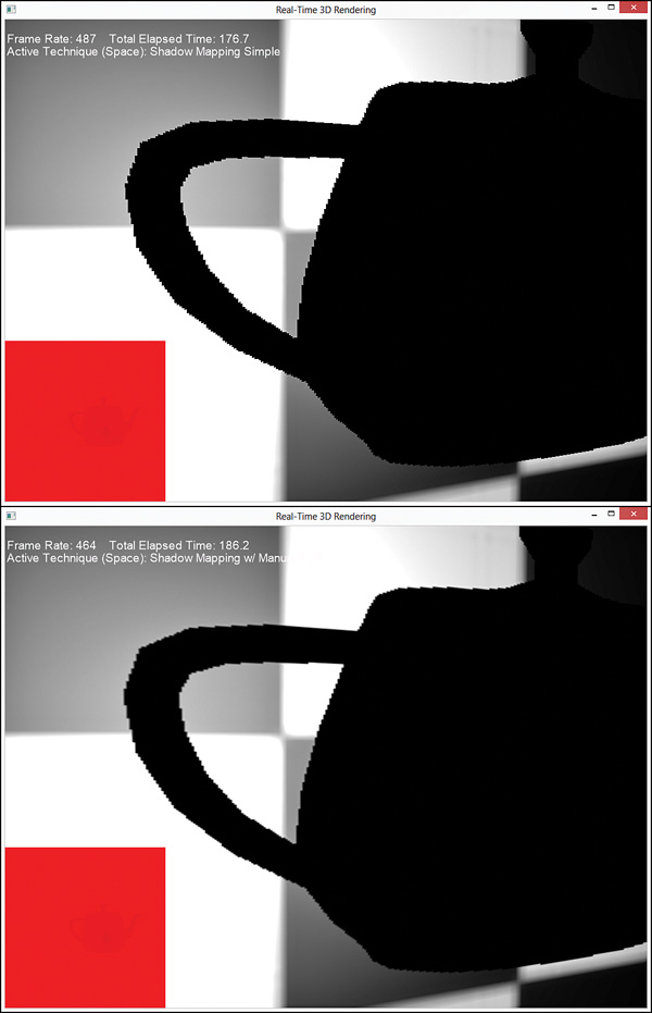
This shader is very similar to the projective texture-mapping shader with occlusion testing. The depth map variable is now named ShadowMap, along with its ShadowMapSampler. But you see the real modifications in the pixel shader. The shadow map is sampled and biased and compared against the pixel depth. If the pixel depth is greater than the sampled depth, then it is in shadow and its diffuse and specular components are modulated by a shadow color (black, in this example), although not the ambient term. Notice that this is an all-or-nothing technique; the pixel is either completely in shadow or not. This produces hard-edged shadows, as in Figure 19.7.
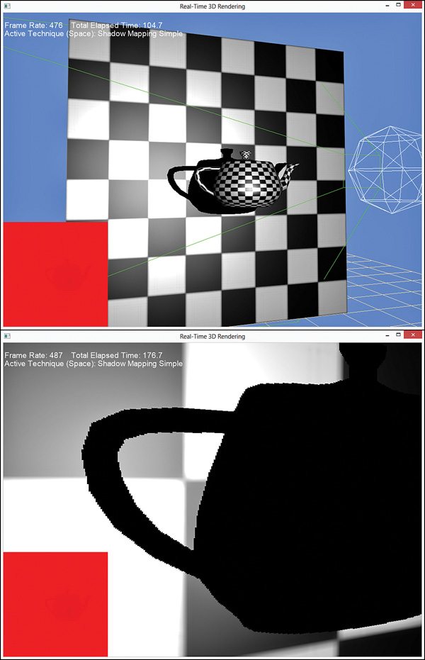
Figure 19.7 Output of the shadow mapping shader (top), zoomed in (bottom) to demonstrate hard shadow edges.
Percentage Closer Filtering
You can soften the edges of the shadow by sampling the depth map multiple times to determine how much of the sampled area is in shadow. This technique is known as percentage closer filtering (PCF). Traditionally, PCF samples a 2×2 grid surrounding the requested UV. Each sample is tested against the object’s pixel depth to determine whether the sample is in shadow, and the results are interpolated. If three samples are in shadow but one is not, the pixel can be described as being 75 percent in shadow. The UVs are computed according to the depth map’s size:
Sample1 = (u, v)
Sample2 = (u + TexelSize.x, v)
Sample3 = (u, v + TexelSize. y)
Sample4 = (u + TexelSize. x, v + TexelSize. y)
Listing 19.9 presents the pixel shader for shadow mapping with PCF.
Listing 19.9 A Shadow-Mapping Shader with Manual PCF
cbuffer CBufferPerFrame
{
/* ... */
float2 ShadowMapSize = { 1024.0f, 1024.0f };
}
float4 shadow_manual_pcf_pixel_shader(VS_OUTPUT IN) : SV_Target
{
float4 OUT = (float4)0;
float3 lightDirection = LightPosition - IN.WorldPosition;
lightDirection = normalize(lightDirection);
float3 viewDirection = normalize(CameraPosition
- IN.WorldPosition);
float3 normal = normalize(IN.Normal);
float n_dot_l = dot(normal, lightDirection);
float3 halfVector = normalize(lightDirection + viewDirection);
float n_dot_h = dot(normal, halfVector);
float4 color = ColorTexture.Sample(ColorSampler,
IN.TextureCoordinate);
float4 lightCoefficients = lit(n_dot_l, n_dot_h, SpecularPower);
float3 ambient = get_vector_color_contribution(AmbientColor, color.
rgb);
float3 diffuse = get_vector_color_contribution(LightColor,
lightCoefficients.y * color.rgb) * IN.Attenuation;
float3 specular = get_scalar_color_contribution(SpecularColor,
min(lightCoefficients.z, color.w)) * IN.Attenuation;
if (IN.ShadowTextureCoordinate.w >= 0.0f)
{
IN.ShadowTextureCoordinate.xyz /= IN.ShadowTextureCoordinate.w;
float2 texelSize = 1.0f / ShadowMapSize;
float sampledDepth1 = ShadowMap.Sample(ShadowMapSampler,
IN.ShadowTextureCoordinate.xy).x + DepthBias;
float sampledDepth2 = ShadowMap.Sample(ShadowMapSampler,
IN.ShadowTextureCoordinate.xy + float2(texelSize.x, 0)).x + DepthBias;
float sampledDepth3 = ShadowMap.Sample(ShadowMapSampler,
IN.ShadowTextureCoordinate.xy + float2(0, texelSize.y)).x + DepthBias;
float sampledDepth4 = ShadowMap.Sample(ShadowMapSampler,
IN.ShadowTextureCoordinate.xy + float2(texelSize.x, texelSize.y)).x +
DepthBias;
float pixelDepth = IN.ShadowTextureCoordinate.z;
float shadowFactor1 = (pixelDepth > sampledDepth1 ? 0.0f :
1.0f);
float shadowFactor2 = (pixelDepth > sampledDepth2 ? 0.0f :
1.0f);
float shadowFactor3 = (pixelDepth > sampledDepth3 ? 0.0f :
1.0f);
float shadowFactor4 = (pixelDepth > sampledDepth4 ? 0.0f :
1.0f);
float2 lerpValues = frac(IN.ShadowTextureCoordinate.xy *
ShadowMapSize);
float shadow = lerp(lerp(shadowFactor1, shadowFactor2,
lerpValues.x), lerp(shadowFactor3, shadowFactor4, lerpValues.x),
lerpValues.y);
diffuse *= shadow;
specular *= shadow;
}
OUT.rgb = ambient + diffuse + specular;
OUT.a = 1.0f;
return OUT;
}
After sampling and biasing the four depths, their “in-shadow factors” are interpolated using the HLSL lerp() function. The interpolation value (how much should be pulled from each source) is determined with the HLSL frac() function, which yields the fractional part of a floating-point number. Figure 19.8 shows the results of PCF compared with the original shadow mapping shader.
Sampling the depth map repeatedly is expensive, and the more samples you take, the more expensive the shader. Thankfully, Direct3D 11 intrinsically supports PCF through the texture object’s SampleCmp() function, which improves performance over manual PCF. Thus, the previous shader can be rewritten to match Listing 19.10.
Listing 19.10 A Shadow-Mapping Shader with Intrinsic PCF
SamplerComparisonState PcfShadowMapSampler
{
Filter = COMPARISON_MIN_MAG_LINEAR_MIP_POINT;
AddressU = BORDER;
AddressV = BORDER;
BorderColor = ColorWhite;
ComparisonFunc = LESS_EQUAL;
};
float4 shadow_pcf_pixel_shader(VS_OUTPUT IN) : SV_Target
{
float4 OUT = (float4)0;
float3 lightDirection = LightPosition - IN.WorldPosition;
lightDirection = normalize(lightDirection);
float3 viewDirection = normalize(CameraPosition
- IN.WorldPosition);
float3 normal = normalize(IN.Normal);
float n_dot_l = dot(normal, lightDirection);
float3 halfVector = normalize(lightDirection + viewDirection);
float n_dot_h = dot(normal, halfVector);
float4 color = ColorTexture.Sample(ColorSampler,
IN.TextureCoordinate);
float4 lightCoefficients = lit(n_dot_l, n_dot_h, SpecularPower);
float3 ambient = get_vector_color_contribution(AmbientColor, color.
rgb);
float3 diffuse = get_vector_color_contribution(LightColor,
lightCoefficients.y * color.rgb) * IN.Attenuation;
float3 specular = get_scalar_color_contribution(SpecularColor,
min(lightCoefficients.z, color.w)) * IN.Attenuation;
IN.ShadowTextureCoordinate.xyz /= IN.ShadowTextureCoordinate.w;
float pixelDepth = IN.ShadowTextureCoordinate.z;
float shadow = ShadowMap.SampleCmpLevelZero(PcfShadowMapSampler,
IN.ShadowTextureCoordinate.xy, pixelDepth).x;
diffuse *= shadow;
specular *= shadow;
OUT.rgb = ambient + diffuse + specular;
OUT.a = 1.0f;
return OUT;
}
Gone from this shader are the manual offset calculations, in-shadow comparisons, and linear interpolations. The SampleCmpLevelZero() function handles all these. This function samples mip-level zero (the only mipmap you create for the depth map) with 2×2 PCF filtering and compares the sampled values against the function’s third argument (the pixel depth). This function requires a SamplerComparisonState object instead of a normal SamplerObject, with a filter of COMPARISION_MIN_MAG_LINEAR_MIP_POINT.
The output is the same, although you must supply the depth bias through a RasterizerState object when you create the depth map. This leads us to the final topic in this chapter, slope-scaled depth biasing.
Slope-Scaled Depth Biasing
To provide a fixed depth bias for intrinsic PCF filtering, modify your DepthMap.fx shader to match Listing 19.11.
Listing 19.11 Setting the Bias When Creating the Depth Map
RasterizerState DepthBias
{
DepthBias = 84000;
};
float4 create_depthmap_vertex_shader(float4 ObjectPosition : POSITION)
: SV_Position
{
return mul(ObjectPosition, WorldLightViewProjection);
}
technique11 create_depthmap_w_bias
{
pass p0
{
SetVertexShader(CompileShader(vs_5_0,
create_depthmap_vertex_shader()));
SetGeometryShader(NULL);
SetPixelShader(NULL);
SetRasterizerState(DepthBias);
}
}
The DepthBias member of the RasterizerState object provides a fixed offset for values as they are written to the depth buffer. This number is used to calculate the final bias as follows:
where, r is the smallest value that can be represented by the floating-point format of the depth buffer (for a 24-bit depth map r = 1/224). Thus, a fixed-depth bias of 0.005 (the default value in the previous iterations of the shadow mapping shader) can be calculated as 0.005 ≈ 84000 * 1/224. The problem with a fixed-depth bias is that your geometry isn’t uniform (with respect to its orientation to the light source). Specifically, as the slope of the triangle increases, so should its bias. Direct3D hardware can intrinsically measure the slope of the triangle and use the RasterizerState.SlopeScaledDepthBias property to calculate the bias dynamically. The SlopeScaledDepthBias is modulated by the MaxDepthSlope, whose value is the maximum of the horizontal and vertical slopes of the depth value at a specific location. Thus, the final bias calculation can be redefined as:
BiasFinal = DepthBias * r + SlopeScaledDepthBias * MaxDepthSlope
Because this value is calculated dynamically, you might want to clamp the bias through the RasterizerState.DepthBiasClamp property. This prevents very large depth values when a polygon is viewed at a sharp angle.
Note
This bias calculation is used when the depth buffer has a UNORM format. Visit the MSDN Direct3D documentation for the depth bias calculation when the depth buffer has a floating-point format.
You might be tempted to skip slope-scaled depth biasing and just choose a large enough fixed bias to accommodate most of your geometry. However, an overly large bias leads to an effect called peter panning, where the shadow appears disconnected from the associated object (the name comes from the children’s book character whose shadow became detached). These values are scene dependent, and you need to experiment to find optimal values. The demo available on the companion website enables you to change these values and visualize the results interactively.
Summary
In this chapter, you explored shadow mapping, a common technique for producing shadows. As an intermediate step, you developed shaders for projective texture mapping, a technique for projecting a 2D texture onto arbitrary geometry. You learned about creating depth maps and occlusion testing, and you applied that work to implement a shadow mapping shader. You also examined various issues with shadow mapping, including shadow acne, hard edges, and peter panning, and you discovered ways to address these problems.
Shadow mapping isn’t the only approach for producing shadows, and more techniques can help with overcoming shadow artifacts. In particular, you might want to investigate cascaded shadow maps and variance shadow maps. Microsoft has a good article on the subject titled “Common Techniques to Improve Shadow Depth Maps,” available online at MSDN. A link to this article is available on the book’s companion website.
Exercises
1. Experiment with all the effects and demo applications from this chapter. Vary the shader inputs, and observe the results.
2. Vary the size of your depth/shadow map, and observe the results. The ShadowMappingDemo application (available on the companion website) uses a 1024×1024 depth map. What happens when you go to 2048×2048 or 4096×4096? What about 256×256?
3. While perspective projection (what we’ve used for the projector in this chapter) is common for simulating shadows for point and spotlights, directional light shadows are typically implemented through orthographic projection. Implement an orthographic projector and integrate it with your shadow-mapping shader.