Chapter 6. Application Protocols for IoT
As with the wired and wireless access technologies discussed in Chapter 5, “IP as the IoT Network Layer,” the IoT application protocols you select should be contingent on the use cases and vertical industries they apply to. In addition, IoT application protocols are dependent on the characteristics of the lower layers themselves. For example, application protocols that are sufficient for generic nodes and traditional networks often are not well suited for constrained nodes and networks.
This chapter focuses on how higher-layer IoT protocols are transported. Specifically, this chapter includes the following sections:
![]() The Transport Layer: IP-based networks use either TCP or UDP. However, the constrained nature of IoT networks requires a closer look at the use of these traditional transport mechanisms.
The Transport Layer: IP-based networks use either TCP or UDP. However, the constrained nature of IoT networks requires a closer look at the use of these traditional transport mechanisms.
![]() IoT Application Transport Methods: This section explores the various types of IoT application data and the ways this data can be carried across a network.
IoT Application Transport Methods: This section explores the various types of IoT application data and the ways this data can be carried across a network.
As in traditional networks, TCP or UDP are utilized in most cases when transporting IoT application data. The transport methods are covered in depth and form the bulk of the material in this chapter. You will notice that, as with the lower-layer IoT protocols, there are typically multiple options and solutions presented for transporting IoT application data. This is because IoT is still developing and maturing and has to account for the transport of not only new application protocols and technologies but legacy ones as well.
The Transport Layer
This section reviews the selection of a protocol for the transport layer as supported by the TCP/IP architecture in the context of IoT networks. With the TCP/IP protocol, two main protocols are specified for the transport layer:
![]() Transmission Control Protocol (TCP): This connection-oriented protocol requires a session to get established between the source and destination before exchanging data. You can view it as an equivalent to a traditional telephone conversation, in which two phones must be connected and the communication link established before the parties can talk.
Transmission Control Protocol (TCP): This connection-oriented protocol requires a session to get established between the source and destination before exchanging data. You can view it as an equivalent to a traditional telephone conversation, in which two phones must be connected and the communication link established before the parties can talk.
![]() User Datagram Protocol (UDP): With this connectionless protocol, data can be quickly sent between source and destination—but with no guarantee of delivery. This is analogous to the traditional mail delivery system, in which a letter is mailed to a destination. Confirmation of the reception of this letter does not happen until another letter is sent in response.
User Datagram Protocol (UDP): With this connectionless protocol, data can be quickly sent between source and destination—but with no guarantee of delivery. This is analogous to the traditional mail delivery system, in which a letter is mailed to a destination. Confirmation of the reception of this letter does not happen until another letter is sent in response.
With the predominance of human interactions over the Internet, TCP is the main protocol used at the transport layer. This is largely due to its inherent characteristics, such as its ability to transport large volumes of data into smaller sets of packets. In addition, it ensures reassembly in a correct sequence, flow control and window adjustment, and retransmission of lost packets. These benefits occur with the cost of overhead per packet and per session, potentially impacting overall packet per second performances and latency.
In contrast, UDP is most often used in the context of network services, such as Domain Name System (DNS), Network Time Protocol (NTP), Simple Network Management Protocol (SNMP), and Dynamic Host Control Protocol (DHCP), or for real-time data traffic, including voice and video over IP. In these cases, performance and latency are more important than packet retransmissions because re-sending a lost voice or video packet does not add value. When the reception of packets must be guaranteed error free, the application layer protocol takes care of that function.
When considering the choice of a transport layer by a given IoT application layer protocol, it is recommended to evaluate the impact of this choice on both the lower and upper layers of the stack. For example, most of the industrial application layer protocols, as discussed later in this chapter, are implemented over TCP, while their specifications may offer support for both transport models. The reason for this is that often these industrial application layer protocols are older and were deployed when data link layers were often unreliable and called for error protection.
While the use of TCP may not strain generic compute platforms and high-data-rate networks, it can be challenging and is often overkill on constrained IoT devices and networks. This is particularly true when an IoT device needs to send only a few bytes of data per transaction. When using TCP, each packet needs to add a minimum of 20 bytes of TCP overhead, while UDP adds only 8 bytes. TCP also requires the establishment and potential maintenance of an open logical channel.
IoT nodes may also be limited by the intrinsic characteristics of the data link layers. For example, low-power and lossy networks (LLNs), as discussed in Chapter 5, may not cope well with supporting large numbers of TCP sessions.
This may explain why a new IoT application protocol, such as Constrained Application Protocol (CoAP), almost always uses UDP and why implementations of industrial application layer protocols may call for the optimization and adoption of the UDP transport layer if run over LLNs. For example, the Device Language Message Specification/Companion Specification for Energy Metering (DLMS/COSEM) application layer protocol, a popular protocol for reading smart meters in the utilities space, is the de facto standard in Europe. Adjustments or optimizations to this protocol should be made depending on the IoT transport protocols that are present in the lower layers. For example, if you compare the transport of DLMS/COSEM over a cellular network versus an LLN deployment, you should consider the following:
![]() Select TCP for cellular networks because these networks are typically more robust and can handle the overhead. For LLNs, where both the devices and network itself are usually constrained, UDP is a better choice and often mandatory.
Select TCP for cellular networks because these networks are typically more robust and can handle the overhead. For LLNs, where both the devices and network itself are usually constrained, UDP is a better choice and often mandatory.
![]() DLMS/COSEM can reduce the overhead associated with session establishment by offering a “long association” over LLNs. Long association means that sessions stay up once in place because the communications overhead necessary to keep a session established is much less than is involved in opening and closing many separate sessions over the same time period. Conversely, for cellular networks, a short association better controls the costs by tearing down the open associations after transmitting.
DLMS/COSEM can reduce the overhead associated with session establishment by offering a “long association” over LLNs. Long association means that sessions stay up once in place because the communications overhead necessary to keep a session established is much less than is involved in opening and closing many separate sessions over the same time period. Conversely, for cellular networks, a short association better controls the costs by tearing down the open associations after transmitting.
![]() When transferring large amounts of DLMS/COSEM data, cellular links are preferred to optimize each open association. Smaller amounts of data can be handled efficiently over LLNs. Because packet loss ratios are generally higher on LLNs than on cellular networks, keeping the data transmission amounts small over LLNs limits the retransmission of large numbers of bytes.
When transferring large amounts of DLMS/COSEM data, cellular links are preferred to optimize each open association. Smaller amounts of data can be handled efficiently over LLNs. Because packet loss ratios are generally higher on LLNs than on cellular networks, keeping the data transmission amounts small over LLNs limits the retransmission of large numbers of bytes.
Multicast requirements are also impacted by the protocol selected for the transport layer. With multicast, a single message can be sent to multiple IoT devices. This is useful in the IoT context for upgrading the firmware of many IoT devices at once. Also, keep in mind that multicast utilizes UDP exclusively.
To guarantee interoperability, certification and compliance profiles, such as Wi-SUN, need to specify the stack from Layer 1 to Layer 4. This enables the chosen technology to be compatible with the different options of the stack while also being compatible with IP. (Chapter 4, “Connecting Smart Objects,” provides more information on Wi-SUN.)
In summary, TCP and UDP are the two main choices at the transport layer for the TCP/IP protocol. The performance and scalability of IoT constrained devices and networks is impacted by which one of these is selected.
IoT Application Transport Methods
Because of the diverse types of IoT application protocols, there are various means for transporting these protocols across a network. Sometimes you may be dealing with legacy utility and industrial IoT protocols that have certain requirements, while other times you might need to consider the transport requirements of more modern application layer protocols. To make these decisions easier, it makes sense to categorize the common IoT application protocols and then focus on the transport methods available for each category. The following categories of IoT application protocols and their transport methods are explored in the following sections:
![]() Application layer protocol not present: In this case, the data payload is directly transported on top of the lower layers. No application layer protocol is used.
Application layer protocol not present: In this case, the data payload is directly transported on top of the lower layers. No application layer protocol is used.
![]() Supervisory control and data acquisition (SCADA): SCADA is one of the most common industrial protocols in the world, but it was developed long before the days of IP, and it has been adapted for IP networks.
Supervisory control and data acquisition (SCADA): SCADA is one of the most common industrial protocols in the world, but it was developed long before the days of IP, and it has been adapted for IP networks.
![]() Generic web-based protocols: Generic protocols, such as Ethernet, Wi-Fi, and 4G/LTE, are found on many consumer- and enterprise-class IoT devices that communicate over non-constrained networks.
Generic web-based protocols: Generic protocols, such as Ethernet, Wi-Fi, and 4G/LTE, are found on many consumer- and enterprise-class IoT devices that communicate over non-constrained networks.
![]() IoT application layer protocols: IoT application layer protocols are devised to run on constrained nodes with a small compute footprint and are well adapted to the network bandwidth constraints on cellular or satellite links or constrained 6LoWPAN networks. Message Queuing Telemetry Transport (MQTT) and Constrained Application Protocol (CoAP), covered later in this chapter, are two well-known examples of IoT application layer protocols.
IoT application layer protocols: IoT application layer protocols are devised to run on constrained nodes with a small compute footprint and are well adapted to the network bandwidth constraints on cellular or satellite links or constrained 6LoWPAN networks. Message Queuing Telemetry Transport (MQTT) and Constrained Application Protocol (CoAP), covered later in this chapter, are two well-known examples of IoT application layer protocols.
Application Layer Protocol Not Present
As introduced in Chapter 4, IETF RFC 7228 devices defined as class 0 send or receive only a few bytes of data. For myriad reasons, such as processing capability, power constraints, and cost, these devices do not implement a fully structured network protocol stack, such as IP, TCP, or UDP, or even an application layer protocol. Class 0 devices are usually simple smart objects that are severely constrained. Implementing a robust protocol stack is usually not useful and sometimes not even possible with the limited available resources.
For example, consider low-cost temperature and relative humidity (RH) sensors sending data over an LPWA LoRaWAN infrastructure. (LPWA and LoRaWAN are discussed in Chapter 4.) Temperature is represented as 2 bytes and RH as another 2 bytes of data. Therefore, this small data payload is directly transported on top of the LoRaWAN MAC layer, without the use of TCP/IP. Example 6-1 shows the raw data for temperature and relative humidity and how it can be decoded by the application.
Example 6-1 Decoding Temperature and Relative Humidity Sensor Data
Temperature data payload over the network: Tx = 0x090c
Temperature conversion required by the application
T = Tx/32 - 50 to T = 0x090c/32 - 50 to T = 2316/32 - 50 = 22.4°
RH data payload over the network: RHx = 0x062e
RH conversion required by the application:
100RH = RHx/16-24 to 100RH = 0x062e/16-24 = 74.9 to RH = 74.9%
While many constrained devices, such as sensors and actuators, have adopted deployments that have no application layer, this transportation method has not been standardized. This lack of standardization makes it difficult for generic implementations of this transport method to be successful from an interoperability perspective.
Imagine expanding Example 6-1 to different kinds of temperature sensors from different manufacturers. These sensors will report temperature data in varying formats. A temperature value will always be present in the data transmitted by each sensor, but decoding this data will be vendor specific. If you scale this scenario out across hundreds or thousands of sensors, the problem of allowing various applications to receive and interpret temperature values delivered in different formats becomes increasingly complex. The solution to this problem is to use an IoT data broker, as detailed in Figure 6-1. An IoT data broker is a piece of middleware that standardizes sensor output into a common format that can then be retrieved by authorized applications. (The concept of the IoT data broker is introduced in Chapter 1, “What Is IoT?”)

In Figure 6-1, Sensors X, Y, and Z are all temperature sensors, but their output is encoded differently. The IoT data broker understands the different formats in which the temperature is encoded and is therefore able to decode this data into a common, standardized format. Applications A, B, and C in Figure 6-1 can access this temperature data without having to deal with decoding multiple temperature data formats.
You should note that IoT data brokers are also utilized from a commercial perspective to distribute and sell IoT data to third parties. Companies can provide access to their data broker from another company’s application for a fee. This makes an IoT data broker a possible revenue stream, depending on the value of the data it contains.
In summary, while directly transporting data payload without a structured network stack clearly optimizes data transmission over low-data-rate networks, the lack of a data model implies that each application needs to know how to interpret the data-specific format. This becomes increasingly complex for larger networks of devices with different data payload formats. Furthermore, it makes the IoT application environment challenging in terms of evolution, development, interoperability, and so on, and often calls for structured data models and data broker applications.
SCADA
In the world of networking technologies and protocols, IoT is relatively new. Combined with the fact that IP is the de facto standard for computer networking in general, older protocols that connected sensors and actuators have evolved and adapted themselves to utilize IP.
A prime example of this evolution is supervisory control and data acquisition (SCADA). Designed decades ago, SCADA is an automation control system that was initially implemented without IP over serial links, before being adapted to Ethernet and IPv4.
A Little Background on SCADA
For many years, vertical industries have developed communication protocols that fit their specific requirements. Many of them were defined and implemented when the most common networking technologies were serial link-based, such as RS-232 and RS-485. This led to SCADA networking protocols, which were well structured compared to the protocols described in the previous section, running directly over serial physical and data link layers.
At a high level, SCADA systems collect sensor data and telemetry from remote devices, while also providing the ability to control them. Used in today’s networks, SCADA systems allow global, real-time, data-driven decisions to be made about how to improve business processes.
SCADA networks can be found across various industries, but you find SCADA mainly concentrated in the utilities and manufacturing/industrial verticals. Within these specific industries, SCADA commonly uses certain protocols for communications between devices and applications. For example, Modbus and its variants are industrial protocols used to monitor and program remote devices via a master/slave relationship. Modbus is also found in building management, transportation, and energy applications. The DNP3 and International Electrotechnical Commission (IEC) 60870-5-101 protocols are found mainly in the utilities industry, along with DLMS/COSEM and ANSI C12 for advanced meter reading (AMR). Both DNP3 and IEC 60870-5-101 are discussed in more detail later in this chapter.
As mentioned previously, these protocols go back decades and are serial based. So, transporting them over current IoT and traditional networks requires that certain accommodations be made from both protocol and implementation perspectives. These accommodations and other adjustments form various SCADA transport methods that are the focus of upcoming sections.
Adapting SCADA for IP
In the 1990s, the rapid adoption of Ethernet networks in the industrial world drove the evolution of SCADA application layer protocols. For example, the IEC adopted the Open System Interconnection (OSI) layer model to define its protocol framework. Other protocol user groups also slightly modified their protocols to run over an IP infrastructure. Benefits of this move to Ethernet and IP include the ability to leverage existing equipment and standards while integrating seamlessly the SCADA subnetworks to the corporate WAN infrastructures.
To further facilitate the support of legacy industrial protocols over IP networks, protocol specifications were updated and published, documenting the use of IP for each protocol. This included assigning TCP/UDP port numbers to the protocols, such as the following:
![]() DNP3 (adopted by IEEE 1815-2012) specifies the use of TCP or UDP on port 20000 for transporting DNP3 messages over IP.
DNP3 (adopted by IEEE 1815-2012) specifies the use of TCP or UDP on port 20000 for transporting DNP3 messages over IP.
![]() The Modbus messaging service utilizes TCP port 502.
The Modbus messaging service utilizes TCP port 502.
![]() IEC 60870-5-104 is the evolution of IEC 60870-5-101 serial for running over Ethernet and IPv4 using port 2404.
IEC 60870-5-104 is the evolution of IEC 60870-5-101 serial for running over Ethernet and IPv4 using port 2404.
![]() DLMS User Association specified a communication profile based on TCP/IP in the DLMS/COSEM Green Book (Edition 5 or higher), or in the IEC 62056-53 and IEC 62056-47 standards, allowing data exchange via IP and port 4059.
DLMS User Association specified a communication profile based on TCP/IP in the DLMS/COSEM Green Book (Edition 5 or higher), or in the IEC 62056-53 and IEC 62056-47 standards, allowing data exchange via IP and port 4059.
Note
The DNP3 protocol is based on the IEC 60870-5 standard. So, while DNP3 is not interoperable with IEC 60870-5, it is very similar in its operation and functionality. Both are associated with SCADA networks, with DNP3 found predominantly in the United States and Canada and IEC 60870-5 in Europe. See Chapter 11, “Utilities,” for a discussion of how these SCADA protocols are used in utilities networks.
These legacy serial protocols have adapted and evolved to utilize IP and TCP/UDP as both networking and transport mechanisms. This has allowed utilities and other companies to continue leveraging their investment in equipment and infrastructure, supporting these legacy protocols with modern IP networks. Let’s dig deeper into how these legacy serial protocols have evolved to use IP by looking specifically at DNP3 as a representative use case.
Like many of the other SCADA protocols, DNP3 is based on a master/slave relationship. The term master in this case refers to what is typically a powerful computer located in the control center of a utility, and a slave is a remote device with computing resources found in a location such as a substation. DNP3 refers to slaves specifically as outstations.
Outstations monitor and collect data from devices that indicate their state, such as whether a circuit breaker is on or off, and take measurements, including voltage, current, temperature, and so on. This data is then transmitted to the master when it is requested, or events and alarms can be sent in an asynchronous manner. The master also issues control commands, such as to start a motor or reset a circuit breaker, and logs the incoming data.
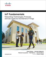
The IEEE 1815-2012 specification describes how the DNP3 protocol implementation must be adapted to run either over TCP (recommended) or UDP. This specification defines connection management between the DNP3 protocol and the IP layers, as shown in Figure 6-2. Connection management links the DNP3 layers with the IP layers in addition to the configuration parameters and methods necessary for implementing the network connection. The IP layers appear transparent to the DNP3 layers as each piece of the protocol stack in one station logically communicates with the respective part in the other. This means that the DNP3 endpoints or devices are not aware of the underlying IP transport that is occurring.
In Figure 6-2, the master side initiates connections by performing a TCP active open. The outstation listens for a connection request by performing a TCP passive open. Dual endpoint is defined as a process that can both listen for connection requests and perform an active open on the channel if required.
Master stations may parse multiple DNP3 data link layer frames from a single UDP datagram, while DNP3 data link layer frames cannot span multiple UDP datagrams. Single or multiple connections to the master may get established while a TCP keepalive timer monitors the status of the connection. Keepalive messages are implemented as DNP3 data link layer status requests. If a response is not received to a keepalive message, the connection is deemed broken, and the appropriate action is taken.
Tunneling Legacy SCADA over IP Networks
Deployments of legacy industrial protocols, such as DNP3 and other SCADA protocols, in modern IP networks call for flexibility when integrating several generations of devices or operations that are tied to various releases and versions of application servers. Native support for IP can vary and may require different solutions. Ideally, end-to-end native IP support is preferred, using a solution like IEEE 1815-2012 in the case of DNP3. Otherwise, transport of the original serial protocol over IP can be achieved either by tunneling using raw sockets over TCP or UDP or by installing an intermediate device that performs protocol translation between the serial protocol version and its IP implementation.
A raw socket connection simply denotes that the serial data is being packaged directly into a TCP or UDP transport. A socket in this instance is a standard application programming interface (API) composed of an IP address and a TCP or UDP port that is used to access network devices over an IP network. More modern industrial application servers may support this capability, while older versions typically require another device or piece of software to handle the transition from pure serial data to serial over IP using a raw socket. Figure 6-3 details raw socket scenarios for a legacy SCADA server trying to communicate with remote serial devices.

In all the scenarios in Figure 6-3, notice that routers connect via serial interfaces to the remote terminal units (RTUs), which are often associated with SCADA networks. An RTU is a multipurpose device used to monitor and control various systems, applications, and devices managing automation. From the master/slave perspective, the RTUs are the slaves. Opposite the RTUs in each Figure 6-3 scenario is a SCADA server, or master, that varies its connection type. In reality, other legacy industrial application servers could be shown here as well.
In Scenario A in Figure 6-3, both the SCADA server and the RTUs have a direct serial connection to their respective routers. The routers terminate the serial connections at both ends of the link and use raw socket encapsulation to transport the serial payload over the IP network.
Scenario B has a small change on the SCADA server side. A piece of software is installed on the SCADA server that maps the serial COM ports to IP ports. This software is commonly referred to as an IP/serial redirector. The IP/serial redirector in essence terminates the serial connection of the SCADA server and converts it to a TCP/IP port using a raw socket connection.
In Scenario C in Figure 6-3, the SCADA server supports native raw socket capability. Unlike in Scenarios A and B, where a router or IP/serial redirector software has to map the SCADA server’s serial ports to IP ports, in Scenario C the SCADA server has full IP support for raw socket connections.
Note
While the examples shown here highlight tunneling of older serial-based SCADA protocols over IP using raw sockets, this mechanism can also be used to tunnel other legacy serial communication protocols that are not part of SCADA.
SCADA Protocol Translation
As mentioned earlier, an alternative to a raw socket connection for transporting legacy serial data across an IP network is protocol translation. With protocol translation, the legacy serial protocol is translated to a corresponding IP version. For example, Figure 6-4 shows two serially connected DNP3 RTUs and two master applications supporting DNP3 over IP that control and pull data from the RTUs. The IoT gateway in this figure performs a protocol translation function that enables communication between the RTUs and servers, despite the fact that a serial connection is present on one side and an IP connection is used on the other.

By running protocol translation, the IoT gateway connected to the RTUs in Figure 6-4 is implementing a computing function close to the edge of the network. Adding computing functions close to the edge helps scale distributed intelligence in IoT networks. This can be accomplished by offering computing resources on IoT gateways or routers, as shown in this protocol translation example. Alternatively, this can also be performed directly on a node connecting multiple sensors. In either case, this is referred to as fog computing. (For more information on fog computing, see Chapter 2, “IoT Network Architecture and Design.”)
In Figure 6-4, DNP3 is shown as the protocol being translated. However, the scenario in this figure is just as applicable to IEC 60870-5. For example, instead of the RTU using DNP3 to connect to the IoT gateway, IEC 60870-5-101 or T101 could be used. On the opposite side, IEC 60870-5-104 or T104 would replace DNP3/IP.
SCADA Transport over LLNs with MAP-T
Due to the constrained nature of LLNs, the implementation of industrial protocols should at a minimum be done over UDP. This in turn requires that both the application servers and devices support and implement UDP. While the long-term evolution of SCADA and other legacy industrial protocols is to natively support IPv6, it must be highlighted that most, if not all, of the industrial devices supporting IP today support IPv4 only. When deployed over LLN subnetworks that are IPv6 only, a transition mechanism, such as MAP-T (Mapping of Address and Port using Translation, RFC 7599), needs to be implemented. This allows the deployment to take advantage of native IPv6 transport transparently to the application and devices.
Figure 6-5 depicts a scenario in which a legacy endpoint is connected across an LLN running 6LoWPAN to an IP-capable SCADA server. The legacy endpoint could be running various industrial and SCADA protocols, including DNP3/IP, Modbus/TCP, or IEC 60870-5-104. In this scenario, the legacy devices and the SCADA server support only IPv4 (typical in the industry today). However, IPv6 (with 6LoWPAN and RPL) is being used for connectivity to the endpoint. As discussed in Chapter 5, 6LoWPAN is a standardized protocol designed for constrained networks, but it only supports IPv6. In this situation, the end devices, the endpoints, and the SCADA server support only IPv4, but the network in the middle supports only IPv6.

The solution to this problem is to use the protocol known as MAP-T, introduced in Chapter 5. MAP-T makes the appropriate mappings between IPv4 and the IPv6 protocols. This allows legacy IPv4 traffic to be forwarded across IPv6 networks. In other words, older devices and protocols can continue running IPv4 even though the network is requiring IPv6.
In Figure 6-5 the IPv4 endpoint on the left side is connected to a Customer Premise Equipment (CPE) device. The MAP-T CPE device has an IPv6 connection to the RPL mesh. On the right side, a SCADA server with native IPv4 support connects to a MAP-T border gateway. The MAP-T CPE device and MAP-T border gateway are thus responsible for the MAP-T conversion from IPv4 to IPv6.
Legacy implementations of SCADA and other industrial protocols are still widely deployed across many industries. While legacy SCADA has evolved from older serial connections to support IP, we can still expect to see mixed deployments for many years. To address this challenge, OT networks require mechanisms such as raw sockets and protocol translation to transport legacy versions over modern IP networks. Even when the legacy devices have IPv4 capability, the constrained portions of the network often require IPv6, not IPv4. In these cases, a MAP-T solution can be put in place to enable IPv4 data to be carried across an IPv6 network.
Generic Web-Based Protocols
Over the years, web-based protocols have become common in consumer and enterprise applications and services. Therefore, it makes sense to try to leverage these protocols when developing IoT applications, services, and devices in order to ease the integration of data and devices from prototyping to production.
The level of familiarity with generic web-based protocols is high. Therefore, programmers with basic web programming skills can work on IoT applications, and this may lead to innovative ways to deliver and handle real-time IoT data. For example, an IoT device generating an event can have the result of launching a video capture, while at the same time a notification is sent to a collaboration tool, such as a Cisco Spark room. This notification allows technicians and engineers to immediately start working on this alert. In addition to a generally high level of familiarity with web-based protocols, scaling methods for web environments are also well understood—and this is crucial when developing consumer applications for potentially large numbers of IoT devices.
Once again, the definition of constrained nodes and networks must be analyzed to select the most appropriate protocol. (Constrained nodes and networks are discussed in Chapter 5.) On non-constrained networks, such as Ethernet, Wi-Fi, or 3G/4G cellular, where bandwidth is not perceived as a potential issue, data payloads based on a verbose data model representation, including XML or JavaScript Object Notation (JSON), can be transported over HTTP/HTTPS or WebSocket. This allows implementers to develop their IoT applications in contexts similar to web applications.
The HTTP/HTTPS client/server model serves as the foundation for the World Wide Web. Recent evolutions of embedded web server software with advanced features are now implemented with very little memory (in the range of tens of kilobytes in some cases). This enables the use of embedded web services software on some constrained devices.
When considering web services implementation on an IoT device, the choice between supporting the client or server side of the connection must be carefully weighed. IoT devices that only push data to an application (for example, an Ethernet- or Wi-Fi-based weather station reporting data to a weather map application or a Wi-Fi–enabled body weight scale that sends data to a health application) may need to implement web services on the client side. The HTTP client side only initiates connections and does not accept incoming ones.
On the other hand, some IoT devices, such as a video surveillance camera, may have web services implemented on the server side. However, because these devices often have limited resources, the number of incoming connections must be kept low. In addition, advanced development in data modeling should be considered as a way to shift the workload from devices to clients, including web browsers on PCs, mobile phones, tablets, and cloud applications.
Interactions between real-time communication tools powering collaborative applications, such as voice and video, instant messaging, chat rooms, and IoT devices, are also emerging. This is driving the need for simpler communication systems between people and IoT devices. One protocol that addresses this need is Extensible Messaging and Presence Protocol (XMPP). (For more information on XMPP-IoT, see www.xmpp-iot.org.)
Note
In IoT networks, it is common to see both Simple Object Access Protocol (SOAP) and representational state transfer (REST) utilized as web services access protocols. Based on Extensible Markup Language (XML), SOAP is verbose and complex from a coding perspective, with a slow parsing speed, but it is versatile and has built-in error handling that can make resolving issues easier. XML is a specification that details a set of rules for encoding documents and other data structures in a way that is readable by both humans and computers.
As a simple, lightweight alternative to SOAP, REST often implements a simple URI or JSON instead of XML for requests. JSON is easier to read and understand than XML. Also, REST itself is not a standard-based protocol like SOAP but an architectural style.
A detailed discussion of the intricacies of SOAP and REST is beyond the scope of this book, but each of them has a place in performing web services in IoT networks. From a high-level perspective, the simplicity of REST makes it suited more for applications on lightweight clients, such as mobile and embedded devices. SOAP, on the other hand, has better adherence to enterprise and business applications and has stronger security requirements. Many coders have the opinion that REST is the future, but at the same time you will find that SOAP is still quite prevalent in certain applications.
In summary, the Internet of Things greatly benefits from the existing web-based protocols. These protocols, including HTTP/HTTPS and XMPP, ease the integration of IoT devices in the Internet world through well-known and scalable programming techniques. However, to fully address constrained devices and networks, optimized IoT protocols are required. These protocols are discussed in the next sections.
IoT Application Layer Protocols
When considering constrained networks and/or a large-scale deployment of constrained nodes, verbose web-based and data model protocols, as discussed in the previous section, may be too heavy for IoT applications. To address this problem, the IoT industry is working on new lightweight protocols that are better suited to large numbers of constrained nodes and networks. Two of the most popular protocols are CoAP and MQTT. Figure 6-6 highlights their position in a common IoT protocol stack.

In Figure 6-6, CoAP and MQTT are naturally at the top of this sample IoT stack, based on an IEEE 802.15.4 mesh network. While there are a few exceptions, you will almost always find CoAP deployed over UDP and MQTT running over TCP. The following sections take a deeper look at CoAP and MQTT.
CoAP
Constrained Application Protocol (CoAP) resulted from the IETF Constrained RESTful Environments (CoRE) working group’s efforts to develop a generic framework for resource-oriented applications targeting constrained nodes and networks. (For more information on the IETF CoRE working group, see https://datatracker.ietf.org/wg/core/charter/.) Constrained nodes and networks are discussed in Chapter 5.
The CoAP framework defines simple and flexible ways to manipulate sensors and actuators for data or device management. The IETF CoRE working group has published multiple standards-track specifications for CoAP, including the following:
![]() RFC 6690: Constrained RESTful Environments (CoRE) Link Format
RFC 6690: Constrained RESTful Environments (CoRE) Link Format
![]() RFC 7252: The Constrained Application Protocol (CoAP)
RFC 7252: The Constrained Application Protocol (CoAP)
![]() RFC 7641: Observing Resources in the Constrained Application Protocol (CoAP)
RFC 7641: Observing Resources in the Constrained Application Protocol (CoAP)
![]() RFC 7959: Block-Wise Transfers in the Constrained Application Protocol (CoAP)
RFC 7959: Block-Wise Transfers in the Constrained Application Protocol (CoAP)
![]() RFC 8075: Guidelines for Mapping Implementations: HTTP to the Constrained Application Protocol (CoAP)
RFC 8075: Guidelines for Mapping Implementations: HTTP to the Constrained Application Protocol (CoAP)
The CoAP messaging model is primarily designed to facilitate the exchange of messages over UDP between endpoints, including the secure transport protocol Datagram Transport Layer Security (DTLS). (UDP is discussed earlier in this chapter.) The IETF CoRE working group is studying alternate transport mechanisms, including TCP, secure TLS, and WebSocket. CoAP over Short Message Service (SMS) as defined in Open Mobile Alliance for Lightweight Machine-to-Machine (LWM2M) for IoT device management is also being considered. (For more information on the Open Mobile Alliance, see http://openmobilealliance.org.)
RFC 7252 provides more details on securing CoAP with DTLS. It specifies how a CoAP endpoint is provisioned with keys and a filtering list. Four security modes are defined: NoSec, PreSharedKey, RawPublicKey, and Certificate. The NoSec and RawPublicKey implementations are mandatory. (For more information about these security modes, see https://tools.ietf.org/html/rfc7252.)
From a formatting perspective, a CoAP message is composed of a short fixed-length Header field (4 bytes), a variable-length but mandatory Token field (0–8 bytes), Options fields if necessary, and the Payload field. Figure 6-7 details the CoAP message format, which delivers low overhead while decreasing parsing complexity.

As you can see in Figure 6-7, the CoAP message format is relatively simple and flexible. It allows CoAP to deliver low overhead, which is critical for constrained networks, while also being easy to parse and process for constrained devices. Table 6-1 provides an overview of the various fields of a CoAP message. (For more details on these fields, see https://tools.ietf.org/html/rfc7252.)

CoAP can run over IPv4 or IPv6. However, it is recommended that the message fit within a single IP packet and UDP payload to avoid fragmentation. For IPv6, with the default MTU size being 1280 bytes and allowing for no fragmentation across nodes, the maximum CoAP message size could be up to 1152 bytes, including 1024 bytes for the payload. In the case of IPv4, as IP fragmentation may exist across the network, implementations should limit themselves to more conservative values and set the IPv4 Don’t Fragment (DF) bit.
While most sensor and actuator traffic utilizes small-packet payloads, some use cases, such as firmware upgrades, require the capability to send larger payloads. CoAP doesn’t rely on IP fragmentation but defines (in RFC 7959) a pair of Block options for transferring multiple blocks of information from a resource representation in multiple request/response pairs.
As illustrated in Figure 6-8, CoAP communications across an IoT infrastructure can take various paths. Connections can be between devices located on the same or different constrained networks or between devices and generic Internet or cloud servers, all operating over IP. Proxy mechanisms are also defined, and RFC 7252 details a basic HTTP mapping for CoAP. As both HTTP and CoAP are IP-based protocols, the proxy function can be located practically anywhere in the network, not necessarily at the border between constrained and non-constrained networks.

Just like HTTP, CoAP is based on the REST architecture, but with a “thing” acting as both the client and the server. Through the exchange of asynchronous messages, a client requests an action via a method code on a server resource. A uniform resource identifier (URI) localized on the server identifies this resource. The server responds with a response code that may include a resource representation. The CoAP request/response semantics include the methods GET, POST, PUT, and DELETE.
Example 6-2 shows the CoAP URI format. You may notice that the CoAP URI format is similar to HTTP/HTTPS. The coap/coaps URI scheme identifies a resource, including host information and optional UDP port, as indicated by the host and port parameters in the URI.
coap-URI = "coap:" "//" host [":" port] path-abempty ["?" query]
coaps-URI = "coaps:" "//" host [":" port] path-abempty ["?" query]
CoAP defines four types of messages: confirmable, non-confirmable, acknowledgement, and reset. Method codes and response codes included in some of these messages make them carry requests or responses. CoAP code, method and response codes, option numbers, and content format have been assigned by IANA as Constrained RESTful Environments (CoRE) parameters. (For more information on these parameters, see www.iana.org/assignments/core-parameters/core-parameters.xhtml.)
While running over UDP, CoAP offers a reliable transmission of messages when a CoAP header is marked as “confirmable.” In addition, CoAP supports basic congestion control with a default time-out, simple stop and wait retransmission with exponential back-off mechanism, and detection of duplicate messages through a message ID. If a request or response is tagged as confirmable, the recipient must explicitly either acknowledge or reject the message, using the same message ID, as shown in Figure 6-9. If a recipient can’t process a non-confirmable message, a reset message is sent.

Figure 6-9 shows a utility operations center on the left, acting as the CoAP client, with the CoAP server being a temperature sensor on the right of the figure. The communication between the client and server uses a CoAP message ID of 0x47. The CoAP Message ID ensures reliability and is used to detect duplicate messages.
The client in Figure 6-9 sends a GET message to get the temperature from the sensor. Notice that the 0x47 message ID is present for this GET message and that the message is also marked with CON. A CON, or confirmable, marking in a CoAP message means the message will be retransmitted until the recipient sends an acknowledgement (or ACK) with the same message ID.
In Figure 6-9, the temperature sensor does reply with an ACK message referencing the correct message ID of 0x47. In addition, this ACK message piggybacks a successful response to the GET request itself. This is indicated by the 2.05 response code followed by the requested data.
CoAP supports data requests sent to a group of devices by leveraging the use of IP Multicast. Implementing IP Multicast with CoAP requires the use of all-CoAP-node multicast addresses. For IPv4 this address is 224.0.1.187, and for IPv6 it is FF0X::FD. These multicast addresses are joined by CoAP nodes offering services to other endpoints while listening on the default CoAP port, 5683. Therefore, endpoints can find available CoAP services through multicast service discovery. A typical use case for multicasting is deploying a firmware upgrade for a group of IoT devices, such as smart meters.
With often no affordable manual configuration on the IoT endpoints, a CoAP server offering services and resources needs to be discovered by the CoAP clients. Services from a CoAP server can either be discovered by learning a URI in a namespace or through the “All CoAP nodes” multicast address. When utilizing the URI scheme for discovering services, the default port 5683 is used for non-secured CoAP, or coap, while port 5684 is utilized for DTLS-secured CoAP, or coaps. The CoAP server must be in listening state on these ports, unless a different port number is associated with the URI in a namespace.
Much as with accessing web server resources, CoAP specifications provide a description of the relationships between resources in RFC 6690, “Constrained RESTful Environments (CoRE) Link Format.” This standard defines the CoRE Link format carried as a payload with an assigned Internet media type. A default entry point for listing to a CoAP server’s resource links is to set a well-known relative URI, such as /.well-known/core.
To improve the response time and reduce bandwidth consumption, CoAP supports caching capabilities based on the response code. To use a cache entry, a CoAP endpoint must validate the presented request and stored response matches, including all options (unless marked as NoCacheKey). This confirms that the stored response is fresh or valid.
A wide range of CoAP implementations are available. Some are published with open source licenses, and others are part of vendor solutions. A good resource for CoAP implementations is http://coap.technology/impls.html.
In summary, CoAP is a key application protocol adapted to the IoT framework. Because its standardization is led by the IETF CoRE working group, it closely coordinates with other IETF working groups, in particular those looking at constrained nodes and networks, such as 6Lo, 6TiSCH, LWIG, RoLL, ACE, and COSE. Therefore, CoAP is fully optimized for IoT constrained nodes and networks, while leveraging traditional web programming techniques to make it easily understandable by the development community. (For more information on CoAP resources, see http://coap.technology/.)
Message Queuing Telemetry Transport (MQTT)
At the end of the 1990s, engineers from IBM and Arcom (acquired in 2006 by Eurotech) were looking for a reliable, lightweight, and cost-effective protocol to monitor and control a large number of sensors and their data from a central server location, as typically used by the oil and gas industries. Their research resulted in the development and implementation of the Message Queuing Telemetry Transport (MQTT) protocol that is now standardized by the Organization for the Advancement of Structured Information Standards (OASIS). (For more information on OASIS, see www.oasis-open.org.)
Considering the harsh environments in the oil and gas industries, an extremely simple protocol with only a few options was designed, with considerations for constrained nodes, unreliable WAN backhaul communications, and bandwidth constraints with variable latencies. These were some of the rationales for the selection of a client/server and publish/subscribe framework based on the TCP/IP architecture, as shown in Figure 6-10.

An MQTT client can act as a publisher to send data (or resource information) to an MQTT server acting as an MQTT message broker. In the example illustrated in Figure 6-10, the MQTT client on the left side is a temperature (Temp) and relative humidity (RH) sensor that publishes its Temp/RH data. The MQTT server (or message broker) accepts the network connection along with application messages, such as Temp/RH data, from the publishers. It also handles the subscription and unsubscription process and pushes the application data to MQTT clients acting as subscribers.
The application on the right side of Figure 6-10 is an MQTT client that is a subscriber to the Temp/RH data being generated by the publisher or sensor on the left. This model, where subscribers express a desire to receive information from publishers, is well known. A great example is the collaboration and social networking application Twitter.
With MQTT, clients can subscribe to all data (using a wildcard character) or specific data from the information tree of a publisher. In addition, the presence of a message broker in MQTT decouples the data transmission between clients acting as publishers and subscribers. In fact, publishers and subscribers do not even know (or need to know) about each other. A benefit of having this decoupling is that the MQTT message broker ensures that information can be buffered and cached in case of network failures. This also means that publishers and subscribers do not have to be online at the same time.
MQTT control packets run over a TCP transport using port 1883. TCP ensures an ordered, lossless stream of bytes between the MQTT client and the MQTT server. Optionally, MQTT can be secured using TLS on port 8883, and WebSocket (defined in RFC 6455) can also be used.
MQTT is a lightweight protocol because each control packet consists of a 2-byte fixed header with optional variable header fields and optional payload. You should note that a control packet can contain a payload up to 256 MB. Figure 6-11 provides an overview of the MQTT message format.

Compared to the CoAP message format in Figure 6-7, you can see that MQTT contains a smaller header of 2 bytes compared to 4 bytes for CoAP. The first MQTT field in the header is Message Type, which identifies the kind of MQTT packet within a message. Fourteen different types of control packets are specified in MQTT version 3.1.1. Each of them has a unique value that is coded into the Message Type field. Note that values 0 and 15 are reserved. MQTT message types are summarized in Table 6-2.

The next field in the MQTT header is DUP (Duplication Flag). This flag, when set, allows the client to notate that the packet has been sent previously, but an acknowledgement was not received.
The QoS header field allows for the selection of three different QoS levels. These are discussed in more detail later in this chapter.
The next field is the Retain flag. Only found in a PUBLISH message (refer to Table 6-2), the Retain flag notifies the server to hold onto the message data. This allows new subscribers to instantly receive the last known value without having to wait for the next update from the publisher.
The last mandatory field in the MQTT message header is Remaining Length. This field specifies the number of bytes in the MQTT packet following this field.
MQTT sessions between each client and server consist of four phases: session establishment, authentication, data exchange, and session termination. Each client connecting to a server has a unique client ID, which allows the identification of the MQTT session between both parties. When the server is delivering an application message to more than one client, each client is treated independently.
Subscriptions to resources generate SUBSCRIBE/SUBACK control packets, while unsubscription is performed through the exchange of UNSUBSCRIBE/UNSUBACK control packets. Graceful termination of a connection is done through a DISCONNECT control packet, which also offers the capability for a client to reconnect by re-sending its client ID to resume the operations.
A message broker uses a topic string or topic name to filter messages for its subscribers. When subscribing to a resource, the subscriber indicates the one or more topic levels that are used to structure the topic name. The forward slash (/) in an MQTT topic name is used to separate each level within the topic tree and provide a hierarchical structure to the topic names. Figure 6-12 illustrates these concepts with adt/lora.adeunis being a topic level and adt/lora/adeunis/0018B2000000023A being an example of a topic name.

Wide flexibility is available to clients subscribing to a topic name. An exact topic can be subscribed to, or multiple topics can be subscribed to at once, through the use of wildcard characters. A subscription can contain one of the wildcard characters to allow subscription to multiple topics at once.
The pound sign (#) is a wildcard character that matches any number of levels within a topic. The multilevel wildcard represents the parent and any number of child levels. For example, subscribing to adt/lora/adeunis/# enables the reception of the whole subtree, which could include topic names such as the following:
![]() adt/lora/adeunis/0018B20000000E9E
adt/lora/adeunis/0018B20000000E9E
![]() adt/lora/adeunis/0018B20000000E8E
adt/lora/adeunis/0018B20000000E8E
![]() adt/lora/adeunis/0018B20000000E9A
adt/lora/adeunis/0018B20000000E9A
The plus sign (+) is a wildcard character that matches only one topic level. For example, adt/lora/+ allows access to adt/lora/adeunis/ and adt/lora/abeeway but not to adt/lora/adeunis/0018B20000000E9E.
Topic names beginning with the dollar sign ($) must be excluded by the server when subscriptions start with wildcard characters (# or +). Often, these types of topic names are utilized for message broker internal statistics. So messages cannot be published to these topics by clients. For example, a subscription to +/monitor/Temp does not receive any messages published to $SYS/monitor/Temp. This topic could be the control channel for this temperature sensor.
PINGREQ/PINGRESP control packets are used to validate the connections between the client and server. Similar to ICMP pings that are part of IP, they are a sort of keepalive that helps to maintain and check the TCP session.
Securing MQTT connections through TLS is considered optional because it calls for more resources on constrained nodes. When TLS is not used, the client sends a clear-text username and password during the connection initiation. MQTT server implementations may also accept anonymous client connections (with the username/password being “blank”). When TLS is implemented, a client must validate the server certificate for proper authentication. Client authentication can also be performed through certificate exchanges with the server, depending on the server configuration.
The MQTT protocol offers three levels of quality of service (QoS). QoS for MQTT is implemented when exchanging application messages with publishers or subscribers, and it is different from the IP QoS that most people are familiar with. The delivery protocol is symmetric. This means the client and server can each take the role of either sender or receiver. The delivery protocol is concerned solely with the delivery of an application message from a single sender to a single receiver. These are the three levels of MQTT QoS:
![]() QoS 0: This is a best-effort and unacknowledged data service referred to as “at most once” delivery. The publisher sends its message one time to a server, which transmits it once to the subscribers. No response is sent by the receiver, and no retry is performed by the sender. The message arrives at the receiver either once or not at all.
QoS 0: This is a best-effort and unacknowledged data service referred to as “at most once” delivery. The publisher sends its message one time to a server, which transmits it once to the subscribers. No response is sent by the receiver, and no retry is performed by the sender. The message arrives at the receiver either once or not at all.
![]() QoS 1: This QoS level ensures that the message delivery between the publisher and server and then between the server and subscribers occurs at least once. In PUBLISH and PUBACK packets, a packet identifier is included in the variable header. If the message is not acknowledged by a PUBACK packet, it is sent again. This level guarantees “at least once” delivery.
QoS 1: This QoS level ensures that the message delivery between the publisher and server and then between the server and subscribers occurs at least once. In PUBLISH and PUBACK packets, a packet identifier is included in the variable header. If the message is not acknowledged by a PUBACK packet, it is sent again. This level guarantees “at least once” delivery.
![]() QoS 2: This is the highest QoS level, used when neither loss nor duplication of messages is acceptable. There is an increased overhead associated with this QoS level because each packet contains an optional variable header with a packet identifier. Confirming the receipt of a PUBLISH message requires a two-step acknowledgement process. The first step is done through the PUBLISH/PUBREC packet pair, and the second is achieved with the PUBREL/PUBCOMP packet pair. This level provides a “guaranteed service” known as “exactly once” delivery, with no consideration for the number of retries as long as the message is delivered once.
QoS 2: This is the highest QoS level, used when neither loss nor duplication of messages is acceptable. There is an increased overhead associated with this QoS level because each packet contains an optional variable header with a packet identifier. Confirming the receipt of a PUBLISH message requires a two-step acknowledgement process. The first step is done through the PUBLISH/PUBREC packet pair, and the second is achieved with the PUBREL/PUBCOMP packet pair. This level provides a “guaranteed service” known as “exactly once” delivery, with no consideration for the number of retries as long as the message is delivered once.
As mentioned earlier, the QoS process is symmetric in regard to the roles of sender and receiver, but two separate transactions exist. One transaction occurs between the publishing client and the MQTT server, and the other transaction happens between the MQTT server and the subscribing client. Figure 6-13 provides an overview of the MQTT QoS flows for the three different levels.

Note
The client on each side of the MQTT flow sets the QoS level. The publishing client side sets the QoS level for communications to the MQTT server. On the other side, the client subscriber sets the QoS level through the subscription with the MQTT server. As illustrated in Figure 6-13, in most cases, QoS remains the same between clients and broker end to end. However, you should be aware that in some scenarios, QoS levels change and are not the same end to end.
As with CoAP, a wide range of MQTT implementations are now available. They are either published as open source licenses or integrated into vendors’ solutions, such as Facebook Messenger. For more information on MQTT implementations, see either the older MQTT.org site, at http://mqtt.org, or check out the MQTT community wiki, at https://github.com/mqtt/mqtt.github.io/wiki.
Note
A free tool for working and experimenting with MQTT is MQTT.fx (shown in Figure 6-12). For more information on MQTT.fx, see www.mqttfx.org.
Now that both CoAP and MQTT have been discussed in detail, you can face questions like “Which protocol is better for a given use case?” and “Which one should I used in my IoT network?” Unfortunately, the answer is not always clear, and both MQTT and CoAP have their place. Table 6-3 provides an overview of the differences between MQTT and CoAP, along with their strengths and weaknesses from an IoT perspective.

In summary, MQTT is different from the “one-to-one” CoAP model in its “many-to-many” subscription framework, which can make it a better option for some deployments. MQTT is TCP-based, and it ensures an ordered and lossless connection. It has a low overhead when optionally paired with UDP and flexible message format, supports TLS for security, and provides for three levels of QoS. This makes MQTT a key application layer protocol for the successful adoption and growth of the Internet of Things.
Summary
This chapter completes the discussion of the IoT protocol stack. Chapter 4 covers the IoT options for the PHY and MAC layers, and Chapter 5 details the options at the network layer. This chapter focuses on the transport of application protocols in IoT networks.
This chapter begins with a discussion of TCP and UDP. Both of these protocols have their place in IoT networks, depending on the application.
The rest of this chapter focuses on the various methods for transporting IoT application data. The first method discussed is application layer protocol not present, in which the data payload is directly transported on top of the lower layers. An IoT data broker is needed to scale this method of transporting application data.
The second method discussed is IP-adapted application layer. This technique utilizes an IP adaptation layer to transport application data that comes from a non-IP stack. Legacy industrial protocols, such as DNP3, fall in this category and require capabilities like raw sockets and protocol translation to successfully communicate across an IP network.
The next method discussed is generic web-based protocols (such as HTTP), which can be used with non-constrained networks, such as Ethernet and Wi-Fi.
The last approach discussed for handling IoT application data at the upper layers is IoT application layer protocols. This method handles constrained nodes and networks and is recommended for most IoT networks. Special protocols, like CoAP and MQTT, handle the IoT application data requirements and are quite efficient for smart objects with a small compute footprint that need to communicate over a low-bandwidth network.