Chapter 4
Nexus Switching
This chapter covers the following topics:
Port Security
When Cisco launched the Nexus product line, it introduced a new category of networking devices called data center switching. Data center switching products provide high-density, high-speed switching capacity to serve the needs of the servers (physical and virtual) in the data center. This chapter focuses on the core components of network switching and how to verify which components are working properly to isolate and troubleshoot Layer 2 forwarding issues.
Network Layer 2 Communication Overview
The Ethernet protocol first used technologies such as Thinnet (10Base2) or Thicknet (10Base5), which connected all the network devices via the same cable. This caused problems when two devices tried to talk at the same time, because Ethernet devices use Carrier Sense Multiple Access/Collision Detect (CSMA/CD) to ensure that only one device talked at time in a collision domain. If a device detected that another device was transmitting data, it delayed transmitting packets until the cable was quiet.
As more devices were added to a cable, the less efficient the network became. All these devices were in the same collision domain (CD). Network hubs proliferated the problem because they added port density while repeating traffic. Network hubs do not have any intelligence in them to direct network traffic.
Network switches enhance scalability and stability in a network through the creation of virtual channels. Switches maintain a table that associate a host’s MAC Ethernet addresses to the port that sourced the network traffic. Instead of flooding all traffic out of every port, a switch uses the MAC address table to forward network traffic only to the destination port associated to the destination MAC address of the packet. Packets are forwarded out of all network ports for that LAN only if the destination MAC address is not known on the switch (known as unicast flooding).
Network broadcasts (MAC Address: ff:ff:ff:ff:ff:ff) cause the switch to broadcast the packet out of every LAN switch port interface. This is disruptive because it diminishes the efficiencies of a network switch to those of a hub because it causes communication between network devices to stop because of CSMA/CD. Network broadcasts do not cross Layer 3 boundaries (that is, from one subnet to another subnet). All devices that reside in the same Layer 2 (L2) segment are considered to be in the same broadcast domain.
Figure 4-1 displays PC-A’s broadcast traffic that is being advertised to all devices on that network, which include PC-B, PC-C, and R1. R1 does not forward the broadcast traffic from one broadcast domain (192.168.1.0/24) to the other broadcast domain (192.168.2.0/24).
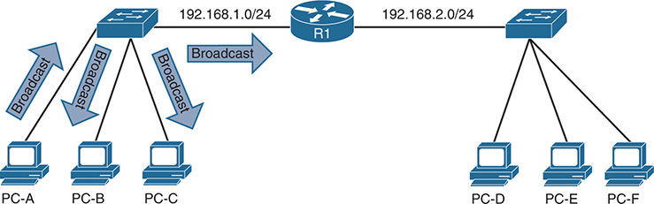
Figure 4-1 Broadcast Domains
The local MAC address table contains the list of MAC addressees and the ports that those MAC addresses learned. The MAC address table is displayed with the command show mac address-table [address mac-address]. To ensure that the switch hardware ASICS are programmed correctly, the hardware MAC address table is displayed with the command show hardware mac address-table module [dynamic] [address mac-address].
Example 4-1 displays the MAC address table on a Nexus switch. Locating the switch port the network device is attached to is the first step of troubleshooting L2 forwarding. If multiple MAC addresses appear on the same port, it indicates that a switch is connected to that port, and that connecting to the switch may be required as part of the troubleshooting processs to identify the port the network device is attached to.
Example 4-1 Viewing the MAC Addresses on a Nexus Switch
Legend:
* - primary entry, G - Gateway MAC, (R) - Routed MAC, O - Overlay MAC
age - seconds since last seen,+ - primary entry using vPC Peer-Link,
(T) - True, (F) - False, C - ControlPlane MAC
VLAN MAC Address Type age Secure NTFY Ports
---------+-----------------+--------+---------+------+----+------------------
* 1 0007.b35b.c420 dynamic 0 F F Eth1/7
* 1 0011.2122.2370 dynamic 0 F F Eth1/6
* 1 0027.e398.5481 dynamic 0 F F Eth1/1
* 1 0027.e398.54c0 dynamic 0 F F Eth1/1
* 1 0035.1a93.e4c2 dynamic 0 F F Eth1/2
* 1 286f.7fa3.e401 dynamic 0 F F Eth1/3
* 1 9caf.ca2e.76c1 dynamic 0 F F Eth1/5
* 1 9caf.ca2e.9041 dynamic 0 F F Eth1/4
G - 885a.92de.617c static - F F sup-eth1(R)
FE |PI| VLAN | MAC |Trunk| TGID |Mod|Port|Virt|Static|Hit|Hit|CPU|Pend
| | | | | | | |Port| | SA| DA| |
---+--+------+-------------+-----+-------+---+----+----+------+---+---+---+----+
0 1 1 286f.7fa3.e401 0 0 1 3 0 1 0 0 0
0 1 1 9caf.ca2e.76c1 0 0 1 5 0 1 1 0 0
0 1 1 0027.e398.5481 0 0 1 1 0 1 0 0 0
0 1 1 0035.1a93.e4c2 0 0 1 2 0 1 0 0 0
0 1 1 0027.e398.54c0 0 0 1 1 0 0 0 0 0
0 1 1 0011.2122.2370 0 0 1 6 0 1 1 0 0
0 1 1 0007.b35b.c420 0 0 1 7 0 1 1 0 0
0 1 1 9caf.ca2e.9041 0 0 1 4 0 1 1 0 0
Note
The terms network device and hosts are considered interchangeable in this text.
Virtual LANs
Adding a router between LAN segments helps shrink broadcast domains and provides for optimal network communication. Host placement on a LAN segment varies because of network addressing. This could lead to inefficient usage of hardware because some switch ports could go unused.
Virtual LANs (VLAN) provide a logical segmentation by creating multiple broadcast domains on the same network switch. VLANs provide higher utilization of switch ports because a port could be associated to the necessary broadcast domain, and multiple broadcast domains can reside on the same switch. Network devices in one VLAN cannot communicate with devices in a different VLAN via traditional L2 or broadcast traffic.
VLANs are defined in the Institute of Electrical and Electronics Engineers (IEEE) 802.1Q standard, which states that 32 bits are added to the packet header and are composed of the following:
Tag protocol identifier (TPID): 16-bit field set to 0x8100 to identify the packet as an 802.1Q.
Priority code point (PCP): A 3-bit field to indicate a class of service (CoS) as part of Layer 2 quality of service (QoS) between switches.
Drop Eligible Indicator (DEI): A 1-bit field that indicates if the packet can be dropped when there is bandwidth contention.
VLAN identifier (VID): A 12-bit field that specifies the VLAN associated to a network packet.
Figure 4-2 displays the VLAN packet structure.

Figure 4-2 VLAN Packet Structure
The VLAN identifier has only 12 bits, which provide 4094 unique VLANs. NX-OS uses the following logic for VLAN identifiers:
VLAN 0 is reserved for 802.1P traffic and cannot be modified or deleted.
VLAN 1 is the default VLAN and cannot be modified or deleted.
VLANs 2 to 1005 are in the normal VLAN range and can be added, deleted, or modified as necessary.
VLANs 1006 to 3967 and 4048 to 4093 are in the extended VLAN range and can be added, deleted, or modified as necessary.
VLANs 3968 to 4047 and 4094 are considered internal VLANs and are used internally by NX-OS. These cannot be added, deleted, or modified.
VLANs 4095 is reserved by 802.1Q standards and cannot be used.
VLAN Creation
VLANs are created by using the global configuration command vlan vlan-id. A friendly name (32 characters) is associated to the VLAN by using the VLAN submode configuration command name name. The VLAN is not created until the CLI has been moved back to the global configuration context or a different VLAN identifier. Example 4-2 demonstrates the creation of VLAN 10 (Accounting), VLAN 20 (HR), and VLAN 30 (Security) on NX-1.
NX-1(config-vlan)# name Accounting
NX-1(config-vlan)# vlan 20
NX-1(config-vlan)# name HR
NX-1(config-vlan)# vlan 30
NX-1(config-vlan)# name Security
VLANs and their port assignment are verified with the show vlan [id vlan-id] command, as demonstrated in Example 4-3. The output is reduced to a specific VLAN by using the optional id keyword. Notice that the output is broken into three separate areas: Traditional VLANs, Remote Switched Port Analyzer (RSPAN) VLANs, and Private VLANs.
Example 4-3 Demonstration of the show vlan Command
---- -------------------------------- --------- -------------------------------
1 default active Eth1/1, Eth1/21, Eth1/22
Eth1/23, Eth1/24, Eth1/25
Eth1/26, Eth1/27, Eth1/28
Eth1/29, Eth1/30, Eth1/31
Eth1/32, Eth1/33, Eth1/34
Eth1/35, Eth1/36, Eth1/37
Eth1/38, Eth1/39, Eth1/40
Eth1/41, Eth1/42, Eth1/43
Eth1/44, Eth1/45, Eth1/46
Eth1/47, Eth1/48, Eth1/49
Eth1/50, Eth1/51, Eth1/52
10 Accounting active Eth1/2, Eth1/3, Eth1/4, Eth1/5
Eth1/6, Eth1/7, Eth1/8, Eth1/9
Eth1/10, Eth1/11, Eth1/12
20 HR active Eth1/13, Eth1/14, Eth1/15
Eth1/16, Eth1/17, Eth1/18
Eth1/19, Eth1/20
30 Security active
VLAN Type Vlan-mode
---- ----- ----------
1 enet CE
10 enet CE
20 enet CE
30 enet CE
-------------------------------------------------------------------------------
------- --------- --------------- -------------------------------------------
VLAN Name Status Ports
---- -------------------------------- --------- -------------------------------
10 Accounting active Eth1/2, Eth1/3, Eth1/4, Eth1/5
Eth1/6, Eth1/7, Eth1/8, Eth1/9
Eth1/10, Eth1/11, Eth1/12
VLAN Type Vlan-mode
---- ----- ----------
10 enet CE
Remote SPAN VLAN
----------------
Disabled
Primary Secondary Type Ports
------- --------- --------------- -------------------------------------------
Note
Most engineers assume that a VLAN maintains a one-to-one ratio of subnet-to-VLAN. Multiple subnets can exist in the same VLAN by assigning a secondary IP address to a router’s interface or by connecting multiple routers to the same VLAN. In situations like this, both subnets are part of the same broadcast domain.
Access Ports
Access ports are the fundamental building block of a managed switch. An access port is assigned to only one VLAN. It carries traffic from the VLAN to the device connected to it, or from the device to other devices on the same VLAN on that switch.
NX-OS places a L2 switch port as an access port by default. The port is configured as an access port with the command switchport mode access. A specific VLAN is associated to the port with the command switchport access vlan vlan-id. If the VLAN is not specified, it defaults to VLAN 1. The 802.1Q tags are not included on packets transmitted or received on access ports.
The switchport mode access command does not appear when looking at the traditional running configuration and requires the optional all keyword, as shown in Example 4-4.
Example 4-4 Viewing the Access Port Configuration Command
switchport access vlan 10
switchport mode access
switchport access vlan 10
The command show interface interface-id displays the mode that the port is using. The assigned VLAN for the port is viewed with the show vlan command, as shown earlier in Example 4-2, or with show interface status. Example 4-5 demonstrates the verification of an access port and the associated VLAN. It is important to verify that both hosts must be on the same VLAN for L2 forwarding to work properly.
Example 4-5 Verification of Access Port Mode
Port mode is access
NX-1# show interface status
--------------------------------------------------------------------------------
Port Name Status Vlan Duplex Speed Type
--------------------------------------------------------------------------------
mgmt0 -- connected routed full 1000 --
Eth1/1 -- connected trunk full 1000 10g
Eth1/2 -- connected 10 full 1000 10g
Trunk Ports
Trunk ports can carry multiple VLANs across them. Trunk ports are typically used when multiple VLANs need connectivity between a switch and another switch, router, or firewall. VLANs are identified by including the 802.1Q headers in the packets as the packet is transmitted across the link. The headers are examined upon the receipt of the packet, associated to the proper VLAN, and then removed.
Trunk ports must be statically defined on Nexus switches with the interface command switchport mode trunk. Example 4-6 displays Eth1/1 being converted to a trunk port.
Example 4-6 Trunk Port Configuration and Verification
Enter configuration commands, one per line. End with CNTL/Z.
NX-1(config)# int eth1/1
NX-1(config-if)# switchport mode trunk
NX-1# show interface eth1/1 | include Port
Port mode is trunk
The command show interface trunk provides a lot of valuable information into the following sections when troubleshooting connectivity between network devices:
The first section list all the interfaces that are trunk ports, status, association to a port-channel, and native VLAN.
The second section of the output displays the list of VLANs that are allowed on the trunk port. Traffic can be minimized on trunk ports to restrict VLANs to specific switches, thereby restricting broadcast traffic, too. Other use cases involve a form of load balancing between network links where select VLANs are allowed on one trunk link, and a different set of VLANs are allowed on a different trunk port.
The third section displays any ports or VLANs that are in an error disabled (Err-disabled) state. Typically, these errors are related with an incomplete virtual port channel (vPC) configuration. vPCs are explained in detail in Chapter 5, “Port Channels, Virtual Port-Channels, and FabricPath.”
The fourth section displays the VLANs that are in a forwarding state on the switch. Ports that are in blocking state are not listed under this section.
Example 4-7 demonstrates the use of the show interface trunk command.
Example 4-7 Output from show interface trunk Command
Port Native Status Port
Vlan Channel
--------------------------------------------------------------------------------
Eth1/1 1 trunking --
--------------------------------------------------------------------------------
--------------------------------------------------------------------------------
Eth1/1 1-4094
--------------------------------------------------------------------------------
--------------------------------------------------------------------------------
Eth1/1 none
--------------------------------------------------------------------------------
--------------------------------------------------------------------------------
Eth1/1 1,10,20,30,99
--------------------------------------------------------------------------------
Port Vlans in spanning tree forwarding state and not pruned
--------------------------------------------------------------------------------
Feature VTP is not enabled
Eth1/1 1,10,20,30,99
Native VLANs
Traffic on a trunk port’s native VLAN does not include the 802.1Q tags. The native VLAN is a port-specific configuration and is changed with the interface command switchport trunk native vlan vlan-id.
The native VLAN should match on both ports, or traffic can change VLANs. Although connectivity between hosts is feasible (assuming that they are on the different VLAN numbers), this causes confusion for most network engineers and is not a best practice.
Note
All switch control-plane traffic is advertised using VLAN 1. As part of Cisco’s security hardening guide, it is recommended to change the native VLAN to something other than VLAN 1. More specifically, it should be set to a VLAN that is not used at all to prevent VLAN hopping.
Allowed VLANs
As stated earlier, VLANs can be restricted from certain trunk ports as a method of traffic engineering. This can cause problems if traffic between two hosts is expected to traverse a trunk link, and the VLAN is not allowed to traverse that trunk port. The interface command switchport trunk allowed vlan-ids specifies the VLANs that are allowed to traverse the link. Example 4-8 displays sample configuration to limit the VLANs that can cross the Eth1/1 trunk link to 1,10, 30, and 99.
Example 4-8 Viewing the VLANs that Are Allowed on a Trunk Link
switchport mode trunk
switchport trunk allowed vlan 1,10,30,99
Note
The full command syntax is switchport trunk allowed {vlan-ids | all | none | add vlan-ids | remove vlan-ids | except vlan-ids} provides a lot of power in a single command.
When scripting configuration changes, it is best to use the add or remove keywords because they are more prescriptive. A common mistake is using the switchport trunk allowed vlan-ids command, where only the VLAN that is being added is listed. This results in the current list being overwritten, causing traffic loss for the VLANs that were omitted.
Private VLANS
Some network designs require segmentation between network devices. This is easily accomplished by two techniques:
Creating unique subnets for every security domain and restricting network traffic with an ACL. Using this technique can waste IP addresses when a host range falls outside of a subnet range (that is, a security zone with 65 hosts requires /25 and results in wasting 63 IP addresses; this does not take into consideration the broadcast and network addresses).
Using private VLANs.
Private VLANs (PVLAN) provide two-tier hierarchy (primary or secondary VLAN) to restrict traffic between ports from a L2 perspective. An explicit mapping between the primary VLAN and secondary VLAN is required to allow communication outside of the PVLAN. Ports are associated into three categories:
Promiscuous: Ports associated to this VLAN are a primary PVLAN (the first tier) and are allowed to communicate to all hosts. Typically, these are ports assigned to a router, firewall, or server that is providing centralized services (DHCP, DNS, and so on).
Isolated: These ports are in a secondary PVLAN (in the second tier of the hierarchy) and are allowed to communicate only with ports associated to the promiscuous PVLAN. Traffic is not transmitted between ports in the same isolated VLAN.
Community: These ports are in a secondary PVLAN and are allowed to communicate with other ports in this VLAN and ports associated to the promiscuous VLAN.
Figure 4-3 demonstrates the usage of PVLANs for a service provider. R1 is the router for every host in the 10.0.0.0/24 network segment and is connected with a promiscuous PVLAN. Host-2 and Host-3 are from different companies and should not be able to communicate with any host. They should only be able to communicate with R1.

Figure 4-3 Sample Private VLAN Topology
Host-4 and Host-5 are from the same third company and need to talk with each other along with R1. Host-6 and Host-7 are from the same fourth company and need to talk with each other along with R1. All other communication is not allowed.
Table 4-1 displays the communication capability between hosts. Notice that Host-4 and Host-5 communicate with each other; but cannot communicate with Host-2, Host-3, Host-6, and Host-7.
Table 4-1 PVLAN Communication Capability
R1 |
Host-2 |
Host-3 |
Host-4 |
Host-5 |
Host-6 |
Host-7 |
|
R1 |
N/A |
✓ |
✓ |
✓ |
✓ |
✓ |
✓ |
Host-2 |
✓ |
N/A |
X |
X |
X |
X |
X |
Host-3 |
✓ |
X |
N/A |
X |
X |
X |
X |
Host-4 |
✓ |
X |
X |
N/A |
✓ |
X |
X |
Host-5 |
✓ |
X |
X |
✓ |
N/A |
X |
X |
Host-6 |
✓ |
X |
X |
X |
X |
N/A |
✓ |
Host-7 |
✓ |
X |
X |
X |
X |
✓ |
N/A |
Isolated Private VLANs
Isolated PVLANs allow communication only with promiscuous ports; thereby, only one isolated PVLAN is needed for one L3 domain. The process for deploying isolated PVLANs on a Nexus switch is as follows:
Step 1. Enable the private VLAN feature. Enable the PVLAN feature with the command feature private-vlan in the global configuration mode.
Step 2. Define the isolated PVLAN. Create the isolated PVLAN with the command vlan vlan-id. Underneath the VLAN configuration context, identify the VLAN as an isolated PVLAN with the command private-vlan isolated.
Step 3. Define the promiscuous PVLAN. Create the promiscuous PVLAN with the command vlan vlan-id. Underneath the VLAN configuration context, identify the VLAN as a promiscuous PVLAN with the command private-vlan primary.
Step 4. Associate the isolated PVLAN to the promiscuous PVLAN. Underneath the promiscuous PVLAN configuration context, associate the secondary (isolated or community) PVLANs with the command private-vlan secondary-pvlan-id. If multiple secondary PVLANs are used, delineate with the use of a comma.
Step 5. Configure the switchport(s) for the promiscuous PVLAN. Change the configuration context to the switch port for the promiscuous host with the command interface interface-id. Change the switch port mode to promiscuous PVLAN with the command switchport mode private-vlan promiscuous.
The switch port must then be associated to the promiscuous PVLAN with the command switchport access vlan promiscuous-vlan-id. A mapping between the promiscuous PVLAN and any secondary PVLANs must be performed using the command switchport private-vlan mapping promiscuous-vlan-id secondary-pvlan-vlan-id. If multiple secondary PVLANs are used, delineate with the use of a comma.
Step 6. Configure the switchport(s) for the isolated PVLAN. Change the configuration context to the switch port for the isolated host with the command interface interface-id. Change the switch port mode to the secondary PVLAN type with the command switchport mode private-vlan host.
The switch port must then be associated to the promiscuous PVLAN with the command switchport access vlan isolated-vlan-id. A mapping between the promiscuous PVLAN and the isolated PVLAN must be performed using the command switchport private-vlan mapping host-association promiscuous-vlan-id isolated-pvlan-vlan-id.
Example 4-9 displays the deployment of VLAN 20 as an isolated PVLAN on NX-1, according to Figure 4-3. VLAN 10 is the promiscuous PVLAN.
Example 4-9 Deployment of an Isolated PVLAN on NX-1
Warning: Private-VLAN CLI entered...
Please disable multicast on this Private-VLAN by removing Multicast related
config(IGMP, PIM, etc.) Please remove any VACL related config on Private-VLANs.
VLAN QOS needs to have atleast one port per ASIC instance.
NX-1(config)# vlan 20
NX-1(config-vlan)# name PVLAN-ISOLATED
NX-1(config-vlan)# private-vlan isolated
NX-1(config-vlan)# vlan 10
NX-1(config-vlan)# name PVLAN-PROMISCOUS
NX-1(config-vlan)# private-vlan primary
NX-1(config-vlan)# private-vlan association 20
NX-1(config-vlan)# exit
NX-1(config)# interface Ethernet1/1
NX-1(config-if)# switchport mode private-vlan promiscuous
NX-1(config-if)# switchport access vlan 10
NX-1(config-if)# switchport private-vlan mapping 10 20
NX-1(config-if)# interface Ethernet1/2
NX-1(config-if)# switchport mode private-vlan host
NX-1(config-if)# switchport access vlan 20
NX-1(config-if)# switchport private-vlan host-association 10 20
NX-1(config-if)# interface Ethernet1/3
NX-1(config-if)# switchport mode private-vlan host
NX-1(config-if)# switchport access vlan 20
NX-1(config-if)# switchport private-vlan host-association 10 20
After configuring a switch for PVLANs, it is recommended to verify the configuration using the command show vlan [private-vlan]. The optional private-vlan keyword only shows the output of the PVLAN section from show vlan.
In Example 4-10, the primary VLAN correlates to the promiscuous PVLAN, the secondary VLAN correlates to the isolated PVLAN, the PVLAN type is confirmed, and all active ports are listed off to the side. The promiscuous ports are always included. If a port is missing, recheck the interface configuration because an error probably exists in the PVLAN mapping configuration.
Primary Secondary Type Ports
------- --------- --------------- -------------------------------------------
10 20 isolated Eth1/1, Eth1/2, Eth1/3
---- -------------------------------- --------- -------------------------------
1 default active Eth1/4, Eth1/5, Eth1/6, Eth1/7
10 PVLAN-PROMISCOUS active
20 PVLAN-ISOLATED active
------- --------- --------------- ------------------------------------------- 10 20 isolated Eth1/1, Eth1/2, Eth1/3
Note
An isolated or community VLAN can be associated with only one primary VLAN.
PVLAN ports require a different port type and are set by the switchport mode private-vlan {promiscuous | host} command. This setting is verified by examining the interface using the show interface command. Example 4-11 displays the verification of the PVLAN switch port type setting.
Example 4-11 Verification of PVLAN Switchport Type
Port mode is Private-vlan promiscuous
Port mode is Private-vlan host
Port mode is Private-vlan host
Another technique is to verify that the isolated PVLAN host devices can reach the promiscuous host device. This is achieved with a simple ping test, as shown in Example 4-12.
Example 4-12 Verification of Isolated PVLAN Communications
Sending 5, 100-byte ICMP Echos to 10.0.0.1, timeout is 2 seconds:
Host-3# ping 10.0.0.1
Sending 5, 100-byte ICMP Echos to 10.0.0.1, timeout is 2 seconds:
Sending 5, 100-byte ICMP Echos to 10.0.0.3, timeout is 2 seconds:
Host-3# ping 10.0.0.2
Sending 5, 100-byte ICMP Echos to 10.0.0.2, timeout is 2 seconds:
Community Private VLANs
A community PVLAN allows communication only with promiscuous ports and other ports in the same community PVLAN. The process for deploying community PVLANs on a Nexus switch is as follows:
Step 1. Enable the private VLAN feature. Enable the PVLAN feature with the command feature private-vlan in the global configuration mode.
Step 2. Define the community PVLAN. Create the community PVLAN with the command vlan vlan-id. Underneath the VLAN configuration context, identify the VLAN as a community PVLAN with the command private-vlan community.
Step 3. Define the promiscuous PVLAN. Create the promiscuous PVLAN with the command vlan vlan-id. Underneath the VLAN configuration context, identify the VLAN as a promiscuous PVLAN with the command private-vlan primary.
Step 4. Associate the community PVLAN to the promiscuous PVLAN. Underneath the promiscuous PVLAN configuration context, associate the secondary (isolated or community) PVLANs with the command private-vlan secondary-pvlan-id. If multiple secondary PVLANs are used, delineate with the use of a comma.
Step 5. Configure the switch port(s) for the promiscuous PVLAN. Change the configuration context to the switch port for the promiscuous host with the command interface interface-id. Change the switch port mode to promiscuous PVLAN with the command switchport mode private-vlan promiscuous.
The switch port must then be associated to the promiscuous PVLAN with the command switchport access vlan promiscuous-vlan-id. A mapping between the promiscuous PVLAN and any secondary PVLANs needs to be performed using the command switchport private-vlan mapping promiscuous-vlan-id secondary-pvlan-vlan-id. If multiple secondary PVLANs are used, delineate with the use of a comma.
Step 6. Configure the switch port(s) for the community PVLAN. Change the configuration context to the switch port for the isolated host with the command interface interface-id. Change the switch port mode to the secondary PVLAN type with the command switchport mode private-vlan host.
The switch port must then be associated to the promiscuous PVLAN with the command switchport access vlan isolated-vlan-id. A mapping between the promiscuous PVLAN and the community PVLAN needs to be performed using the command switchport private-vlan mapping host-association promiscuous-vlan-id community-pvlan-vlan-id.
Example 4-13 displays the deployment of VLAN 30 as a community PVLAN for Host-4 and Host-5 along with VLAN 40 for Host-6 and Host-7, according to Figure 4-3. VLAN 10 is the promiscuous PVLAN.
Example 4-13 Deployment of Community PVLANs on NX-1
NX-1(config-vlan)# name PVLAN-COMMUNITY1 10 40
NX-1(config-vlan)# private-vlan community
NX-1(config-vlan)# vlan 40
NX-1(config-vlan)# name PVLAN-COMMUNITY2
NX-1(config-vlan)# private-vlan community
NX-1(config-vlan)# vlan 10
NX-1(config-vlan)# name PVLAN-PROMISCOUS
NX-1(config-vlan)# private-vlan primary
NX-1(config-vlan)# private-vlan association 20,30,40
NX-1(config-vlan)# exit
NX-1(config)# interface Ethernet1/1
NX-1(config-if)# switchport mode private-vlan promiscuous
NX-1(config-if)# switchport access vlan 10
NX-1(config-if)# switchport private-vlan mapping 10 20,30,40
NX-1(config-if)# interface Ethernet1/4
NX-1(config-if)# switchport mode private-vlan host
NX-1(config-if)# switchport access vlan 30
NX-1(config-if)# switchport private-vlan host-association 10 30
NX-1(config-if)# interface Ethernet1/5
NX-1(config-if)# switchport mode private-vlan host
NX-1(config-if)# switchport access vlan 30
NX-1(config-if)# switchport private-vlan host-association 10 30
NX-1(config-if)# interface Ethernet1/6
NX-1(config-if)# switchport mode private-vlan host
NX-1(config-if)# switchport access vlan 40
NX-1(config-if)# switchport private-vlan host-association 10 40
NX-1(config-if)# interface Ethernet1/7
NX-1(config-if)# switchport mode private-vlan host
NX-1(config-if)# switchport access vlan 40
NX-1(config-if)# switchport private-vlan host-association 10 40
Note
VLAN 20 was a part of the promiscuous port configuration to demonstrate how isolated and community PVLANs co-exist as a continuation of the previous configuration to provide the solution shown in Figure 4-3.
Verification of community PVLANs is accomplished with the command show vlan [private-vlan]. Remember that if a port is missing in the PVLAN section, recheck the interface configuration because an error probably exists in the mapping configuration.
Example 4-14 displays all the PVLANS and associated ports. Notice how VLAN 10 is the primary VLAN for VLAN 20, 30, and 40.
Example 4-14 Verifying Community PVLAN Configuration
VLAN Name Status Ports
---- -------------------------------- --------- -------------------------------
1 default active
10 PVLAN-PROMISCOUS active
20 PVLAN-ISOLATED active
30 PVLAN-COMMUNITY1 active
40 PVLAN-COMMUNITY2 active
------- --------- --------------- -------------------------------------------
10 20 isolated Eth1/1, Eth1/2, Eth1/3
10 30 community Eth1/1, Eth1/4, Eth1/5
10 40 community Eth1/1, Eth1/6, Eth1/7
Example 4-15 provides basic verification that all hosts in the isolated and community PVLANs can reach R1. All hosts are not allowed to reach any other host in the isolated PVLAN, whereas hosts in community PVLANs can only reach hosts in the same community PVLAN.
Example 4-15 Verifying Connectivity Between PVLANs
Sending 5, 100-byte ICMP Echos to 10.0.0.1, timeout is 2 seconds:
!!!!!
Success rate is 100 percent (5/5), round-trip min/avg/max = 1/2/9 ms
Host-6# ping 10.0.0.1
Sending 5, 100-byte ICMP Echos to 10.0.0.1, timeout is 2 seconds:
!!!!!
Success rate is 100 percent (5/5), round-trip min/avg/max = 1/2/4 ms
Sending 5, 100-byte ICMP Echos to 10.0.0.5, timeout is 2 seconds:
!!!!!
Success rate is 100 percent (5/5), round-trip min/avg/max = 1/5/9 ms
Host-6# ping 10.0.0.7
Type escape sequence to abort.
Sending 5, 100-byte ICMP Echos to 10.0.0.7, timeout is 2 seconds:
!!!!!
Success rate is 100 percent (5/5), round-trip min/avg/max = 1/1/1 ms
Sending 5, 100-byte ICMP Echos to 10.0.0.6, timeout is 2 seconds:
.....
Success rate is 0 percent (0/5)
Host-6# ping 10.0.0.4
Sending 5, 100-byte ICMP Echos to 10.0.0.4, timeout is 2 seconds:
.....
Success rate is 0 percent (0/5)
Sending 5, 100-byte ICMP Echos to 10.0.0.2, timeout is 2 seconds:
.....
Success rate is 0 percent (0/5)
Host-6# ping 10.0.0.2
Sending 5, 100-byte ICMP Echos to 10.0.0.2, timeout is 2 seconds:
.....
Success rate is 0 percent (0/5)
Using a Promiscuous PVLAN Port on Switched Virtual Interface
A switched virtual interface (SVI) can be configured as a promiscuous port for a PVLAN. The primary and secondary PVLAN mappings are performed as previously explained, but the VLAN interface has the command private-vlan mapping secondary-vlan-id. Example 4-16 demonstrates NX-1 adding the SVI for VLAN 10 with the IP address of 10.0.0.10/24.
Example 4-16 Configuring Promiscuous PVLAN SVI
NX-1(config)# interface vlan 10
NX-1(config-if)# ip address 10.0.0.10/24
NX-1(config-if)# private-vlan mapping 20,30,40
NX-1(config-if)# no shut
NX-1(config-if)# do show run vlan
vlan 10
name PVLAN-PROMISCOUS
private-vlan primary
private-vlan association 20,30,40
vlan 20
name PVLAN-ISOLATED
private-vlan isolated
vlan 30
name PVLAN-COMMUNITY1
private-vlan community
vlan 40
name PVLAN-COMMUNITY2
private-vlan community
The promiscuous PVLAN SVI port mapping is confirmed with the command show interface vlan promiscuous-vlan-id private-vlan mapping, as shown in Example 4-17.
Example 4-17 Verification of Promiscuous PVLAN SVI Mapping
Interface Secondary VLAN
--------- ----------------------------------------------------------------
vlan10 20 30 40
Example 4-18 demonstrates the connectivity between the hosts with the promiscuous PVLAN SVI. The two promiscuous devices (NX-1 and R1) can ping each other. In addition, all the hosts (demonstrated by Host-2) ping both NX-1 and R1 without impacting the PVLAN functionality assigned to isolated or community PVLAN ports.
Example 4-18 Connectivity Verification with Promiscuous PVLAN SVI
PING 10.0.0.1 (10.0.0.1): 56 data bytes64 bytes from 10.0.0.1: icmp_seq=0 ttl=254 time=2.608 ms
64 bytes from 10.0.0.1: icmp_seq=1 ttl=254 time=2.069 ms
64 bytes from 10.0.0.1: icmp_seq=2 ttl=254 time=2.241 ms
64 bytes from 10.0.0.1: icmp_seq=3 ttl=254 time=2.157 ms
64 bytes from 10.0.0.1: icmp_seq=4 ttl=254 time=2.283 ms
--- 10.0.0.1 ping statistics ---
5 packets transmitted, 5 packets received, 0.00% packet loss
round-trip min/avg/max = 2.069/2.271/2.608 ms
Sending 5, 100-byte ICMP Echos to 10.0.0.1, timeout is 2 seconds:
!!!!!
Success rate is 100 percent (5/5), round-trip min/avg/max = 1/8/25 ms
Host-2# ping 10.0.0.10
Sending 5, 100-byte ICMP Echos to 10.0.0.10, timeout is 2 seconds:
!!!!!
Success rate is 100 percent (5/5), round-trip min/avg/max = 1/1/1 ms
Host-2# ping 10.0.0.3
Type escape sequence to abort.
Sending 5, 100-byte ICMP Echos to 10.0.0.3, timeout is 2 seconds:
.....
Success rate is 0 percent (0/5)
Trunking PVLANs Between Switches
Some topologies require that a PVLAN span across multiple switches. In these designs, there are three possible options depending upon the capabilities of the upstream or downstream switch. These scenarios are as follows:
All switches support PVLANs: In this scenario, all the PVLANs and their primary/secondary mappings must be configured on both upstream and downstream switches. A normal 802.1Q trunk link is established between the devices. The switch with the promiscuous port is responsible for directing traffic to/from the promiscuous port. In this scenario, spanning tree maintains a separate instance for each of the PVLANs.
The upstream switch does not support PVLANs: In this scenario, the PVLANs and their primary/secondary mappings must be configured on the downstream switch. Because the upstream switch does not support PVLANs, the downstream switch must merge/separate the secondary PVLANs to the primary PVLANs so that devices on the upstream switch only need to use the primary PVLAN-ID. The upstream trunk switch port is configured with the command switchport mode private-vlan trunk promiscuous. These trunk ports are often referred to as promiscuous PVLAN trunk ports.
The downstream switch does not support PVLANs: In this scenario, the PVLANs and their primary/secondary mappings must be configured on the upstream switch. Because the downstream switch does not support PVLANs, the upstream switch must merge/separate the secondary PVLANs to the primary PVLANs so that devices on the downstream switch only need to use the secondary PVLAN-ID. The downstream trunk switch port is configured with the command switchport mode private-vlan trunk secondary. These trunk ports are often referred to as isolated PVLAN trunk ports.
Note
In all three scenarios, regular VLANs are transmitted across the trunk link.
Note
Not all Nexus platforms support the promiscuous or isolated PVLAN trunk ports. Check www.cisco.com for feature parity.
Spanning Tree Protocol Fundamentals
A good network design provides redundancy in devices and network links (paths). The simplest solution involves adding a second link between switches to overcome network link failure, or ensuring that a switch is connected to at least two switches in a topology.
However, these topologies cause problems when a switch has to forward broadcasts or unknown unicast flooding occurs. Network broadcasts forward in a continuous loop until the link becomes saturated and the switch is forced to drop packets. In addition, the MAC address table will be constantly changing ports as the packets make loops, therefore increasing CPU and memory consumption and probably crashing the switch.
The Spanning Tree Protocol is the protocol that builds a L2 loop-free topology in an environment by temporarily blocking traffic on specific ports. The Spanning Tree Protocol has multiple iterations:
802.1D is the original specification
Per-VLAN Spanning Tree (PVST)
Per-VLAN Spanning Tree Plus (PVST+)
802.1W Rapid Spanning Tree Protocol (RSTP)
802.1S Multiple Spanning Tree Protocol (MST)
Nexus switches operate as RSTP or MST mode only. Both of these are backward compatible with 802.1D standards.
IEEE 802.1D Spanning Tree Protocol
The original version of STP comes from the IEEE 802.1D standards and provides support for ensuring a loop-free topology for one VLAN. In the Spanning Tree Protocol, every port transitions through a series of the following states:
Disabled: The port is in an administratively off position (that is, shutdown).
Blocking: The switch port is enabled, but the port is not forwarding any traffic to ensure a loop is created. The switch does not modify the MAC address table. It can only receive Bridge Protocol Data Units (BPDU) from other switches.
Listening: The switch port has transitioned from a blocking state and can now send or receive BPDUs. It cannot forward any other network traffic.
Learning: The switch port can now modify the MAC address table with any network traffic that it receives. The switch still does not forward any other network traffic besides BPDUs. The switch port transitions into this state after the forward delay has expired.
Forwarding: The switch port can forward all network traffic and can update the MAC address table as expected. This is the final state for a switch port to forward network traffic.
Broken: The switch has detected a configuration or operational problem on a port that can have major effects. The port will discard packets for as long as the problem continues to exist.
The original Spanning Tree Protocol defined the following three port types:
Designated port: A network port that receives and forwards frames to other switches. Designated ports provide connectivity to downstream devices and switches.
Root port: A network port that connects to the root switch or an upstream switch in the spanning-tree topology.
Blocking port: A network that is not forwarding traffic because of Spanning Tree Protocol.
Within the Spanning Tree Protocol are a couple key terms that must be understood:
Root bridge: The root bridge is the most important switch in the L2 topology. All ports are in a forwarding state. This switch is considered the top of the spanning-tree for all path calculations by other switches. All ports on the root bridge are categorized as designated ports.
Bridge Protocol Data Unit (BPDU): This network frame is used strictly for detecting the STP topology so that switches can identify the root bridge, root ports, designated ports, and blocking ports. The BPDU consists of the following fields: STP Type, Root Path Cost, Root Bridge Identifier, Local Bridge Identifier, Max Age, Hello Time, Forward Delay. The BPDU uses a destination MAC address of 01:80:c2:00:00:00.
Root Path Cost: The combination of the cost for a specific path toward the root switch.
Root Bridge Identifier: Combination of the root bridge system MAC, system-ID extension, and system priority of the root bridge.
Local Bridge Identifier: Combination of the advertising switch’s bridge system MAC, System ID extension, and system priority of the root bridge.
Max Age: The timer the controls the maximum length of time that passes before a bridge port saves its BPDU information. On Nexus switches, this is relevant for backward compatibility with switches using traditional 802.1D STP.
Hello Time: The time that a BPDU is advertised out of a port. The default value is 2 seconds and is configured to a value of 1 to 10 seconds with the command spanning-tree vlan vlan-id hello-time hello-time.
Forward Delay: The amount of time that a port stays in a listening and learning state. The default value is 15 seconds and can be changed to a value of 15 to 30 seconds with the command spanning-tree vlan vlan-id forward-time forward-time.
Note
A lot of STP terminology uses the term bridge, even though STP runs on switches. The term bridge and switch are interchangeable in this context.
Rapid Spanning Tree Protocol
802.1 D (the first version of Spanning Tree Protocol) created only one topology tree. For larger environments with multiple VLANs, creating different Spanning Tree Protocol topologies allowed for different VLANs to use different links. Cisco created Per-VLAN Spanning Tree (PVST) and Per-VLAN Spanning Tree Plus (PVST+) to allow for such flexibility.
PVST and PVST+ were proprietary spanning protocols. The concepts in these protocols were incorporated with other enhancements to form the IEEE 802.1W specification. The 802.1Q specification incorporated additional enhancements to provide faster convergence and is called Rapid Spanning Tree Protocol (RSTP).
RSTP defines the following port roles:
Designated port: A network port that receives and forwards frames to other switches. Designated ports provide connectivity to downstream devices and switches.
Root port: (RP) A network port that connects to the root switch or an upstream switch in the spanning-tree topology.
Alternate port: A network port that provides alternate connectivity toward the root switch via a different switch.
Backup port: A network port that provides link redundancy toward the current root switch. The backup port cannot guarantee connectivity to the root bridge in the event the upstream switch fails. A backup port exists only when multiple links connect between the same switches.
With RSTP protocol, switches exchange handshakes with other switches to transition through the following Spanning Tree Protocol states faster:
Discarding: The switch port is enabled, but the port is not forwarding any traffic to ensure a loop is created. This state combines the traditional Spanning Tree Protocol states of Disabled, Blocking, and Listening.
Learning: The switch port now modifies the MAC address table with any network traffic that it receives. The switch still does not forward any other network traffic besides BPDUs.
Forwarding: The switch port forwards all network traffic and updates the MAC address table as expected. This is the final state for a switch port to forward network traffic.
Note
A switch tries to establish an RSTP handshake with the device connected to the port. If a handshake does not occur, the other device is assumed to be non-RSTP compatible, and the port defaults to regular 802.1D behavior. This means that host devices such as computers and printers still encounter a significant transmission delay (~50 seconds) after the network link is established.
Note
RSTP is enabled by default for any L2 switch port with a basic configuration. Additional configuration can be applied to the switch to further tune RSTP.
Spanning-Tree Path Cost
The interface Spanning Tree Protocol cost is an essential component for root path calculation because the root path is found based upon the cumulative interface Spanning Tree Protocol cost to reach the root bridge. The interface Spanning Tree Protocol cost is associated based upon a reference value of 20 Gbps. Table 4-2 displays a list of interface speeds and the correlating interface Spanning Tree Protocol cost.
Table 4-2 Default Interface Spanning Tree Protocol Port Costs
Link Speed |
Interface Spanning Tree Protocol Cost |
10 Mbps |
100 |
100 Mbps |
19 |
1 Gbps |
4 |
10 Gbps |
2 |
20 Gbps or faster |
1 |
Root Bridge Election
The first step with Spanning Tree Protocol is to identify the root bridge. As a switch initializes, it assumes that it is the root bridge and uses the local bridge identifier as the root bridge identifier. It then listens to its neighbor’s BPDU and does the following:
If the neighbor’s BPDU is inferior to its own BPDU, the switch ignores that BPDU.
If the neighbor’s BPDU is preferred to its own BPDU, the switch updates its BPDUs to include the new root bridge identifier along with a new root path cost that correlates the total path cost to reach the new root bridge. This process continues until all switches in a topology have identified the root bridge switch.
Spanning Tree Protocol deems a switch more preferable if the priority in the bridge identifier is lower than other BPDUs. If the priority is the same, the switch prefers the BPDU with the lower system MAC.
Note
Generally, older switches have a lower MAC address and are considered more preferable. Configuration changes can be made for optimizing placement of the root switch in a L2 topology.
Figure 4-4 provides a simple topology to demonstrate some important spanning-tree concepts. In this topology, NX-1, NX-2, NX-3, NX-4, and NX-5 all connect to each other. The configuration on all the switches do not include any customizations for Spanning Tree Protocol, and the focus is primarily on VLAN 1, but VLANs 10, 20, and 30 exist in the topology. NX-1 has been identified as the root bridge because its system MAC address (5e00.4000.0007) is the lowest in the topology.

Figure 4-4 Basic Spanning Tree Protocol Topology
The root bridge is identified with the command show spanning-tree root. Example 4-19 demonstrates the command being executed on NX-1. The output includes the VLAN number, root bridge identifier, root path cost, hello time, max age time, and forwarding delay. Because NX-1 is the root bridge, all ports are designated, so the Root Port field displays This bridge is root.
Example 4-19 Verification of Spanning Tree Protocol Root Bridge
Root Hello Max Fwd
Vlan Root ID Cost Time Age Dly Root Port
---------------- -------------------- ------- ----- --- --- ----------------
VLAN0001 32769 5e00.4000.0007 0 2 20 15 This bridge is root
VLAN0010 32778 5e00.4000.0007 0 2 20 15 This bridge is root
VLAN0020 32788 5e00.4000.0007 0 2 20 15 This bridge is root
VLAN0030 32798 5e00.4000.0007 0 2 20 15 This bridge is root
The same command is run on NX-2 and NX-3 with the output displayed in Example 4-20. The Root ID field is the same as NX-1; however, the root path cost has changed to 2 because both switches must use the 10 Gbps link to reach NX-1. Eth 1/1 has been identified on both of these switches as the root port.
Example 4-20 Identification of Root Ports
Root Hello Max Fwd
Vlan Root ID Cost Time Age Dly Root Port
---------------- -------------------- ------- ----- --- --- ----------------
VLAN0001 32769 5e00.4000.0007 2 2 20 15 Ethernet1/1
VLAN0010 32778 5e00.4000.0007 2 2 20 15 Ethernet1/1
VLAN0020 32788 5e00.4000.0007 2 2 20 15 Ethernet1/1
VLAN0030 32798 5e00.4000.0007 2 2 20 15 Ethernet1/1
Locating Root Ports
After the switches have identified the root bridge, they must determine their Root Port (RP). The root bridge continues to advertise BPDUs out all of its ports. The switch compares the BPDU information to identify the RP. The RP is selected using the following logic: (The next criteria is used if there is a tie.)
The interface associated to lowest path cost is more preferred.
The interface associated to the lowest system priority of the advertising switch.
The interface associated to the lowest system MAC address of the advertising switch.
When multiple links are associated to the same switch, the lowest port priority from the advertising router is preferred.
When multiple links are associated to the same switch, the lower port number from the advertising router is preferred.
The command show spanning-tree root is run on NX-4 and NX-5 with the output displayed in Example 4-21. The Root ID field is the same as NX-1 from Example 4-20; however, the root path cost has changed to 4 because both switches must traverse two 10 Gbps link to reach NX-1. Eth1/3 was identified as the RP on both switches.
Example 4-21 Identification of Root Ports on NX-4 and NX-5
Root Hello Max Fwd
Vlan Root ID Cost Time Age Dly Root Port
---------------- -------------------- ------- ----- --- --- ----------------
VLAN0001 32769 5e00.4000.0007 4 2 20 15 Ethernet1/3
Vlan Root ID Cost Time Age Dly Root Port
---------------- -------------------- ------- ----- --- --- ----------------
VLAN0001 32769 5e00.4000.0007 4 2 20 15 Ethernet1/3
Locating Blocked Switch Ports
Now that the root bridge and RPs are identified, all other ports are considered designated ports. However, if two switches are connected to each other on their designated ports, one of those switch ports must be set to a blocking state to prevent a forwarding loop. The logic to calculate which ports should be blocked between the two switches is the following:
The interface must not be considered as a RP.
The system priority of the local switch is compared to the system priority of the remote switch. The local port is moved to a blocking state if the remote system priority is lower than the local switch.
The system MAC address of the local switch is compared to the system priority of the remote switch. The local port is moved to a blocking state if the remote system MAC address is lower than the local switch.
Note
Step 3 is the last step of the selection process. If a switch has multiple links toward the root switch, the downstream switch always identifies the RP. All other ports will match the criteria for Step 2 or Step 3 and are placed into a blocking state.
The command show spanning-tree [vlan vlan-id] is used to provide useful information for locating a port’s Spanning Tree Protocol state. Example 4-22 displays NX-1’s Spanning Tree Protocol information for VLAN 1. The first portion of the output displays the relevant root bridge’s information, which is then followed by the local bridge’s information. The associated interface’s Spanning Tree Protocol port cost, port priority, and port type are displayed as well. All of NX-1’s ports are designated ports (Desg) because it is the root bridge.
There are three port types expected on NX-OS switches:
Point-to-Point (P2P): This port type connects with another network device (PC or RSTP switch).
P2P Peer (STP): This port type detects that it is connected to an 802.1D switch and is operating with backward compatibility.
Network P2P: This port type is specifically configured to connect with another RSTP switch and to provide bridge assurance.
Edge P2P: This port type is specifically configured to connect with another host device (PC, not a switch). Portfast is enabled on this port.
Example 4-22 NX-1’s Spanning Tree Protocol Information
VLAN0001
Spanning tree enabled protocol rstp
Address 5e00.4000.0007
This bridge is the root
Hello Time 2 sec Max Age 20 sec Forward Delay 15 sec
Address 5e00.4000.0007
Hello Time 2 sec Max Age 20 sec Forward Delay 15 sec
Interface Role Sts Cost Prio.Nbr Type
---------------- ---- --- --------- -------- --------------------------------
Eth1/1 Desg FWD 2 128.1 P2p
Eth1/2 Desg FWD 2 128.2 P2p
Eth1/3 Desg FWD 2 128.3 P2p
Note
If the Type field includes *TYPE_Inc –, this indicates a port configuration mismatch between the Nexus switch and the switch to which it is connected. It is either the port type, or the port mode (access versus trunk) is misconfigured.
Example 4-23 displays the Spanning Tree Protocol topology from NX-2 and NX-3. Notice that in the first root bridge section, the output provides the total root path cost and the port on the switch that is identified as the RP.
All the ports on NX-2 are in a forwarding state, but port Eth1/2 on NX-3 is in a blocking (BLK) state. Specifically, that port has been designated as an alternate port to reach the root in the event that Eth1/1 connection fails.
The reason that NX-3’s Eth1/2 port was placed into a blocking state versus NX-2’s Eth1/3 port is that NX-2’s system MAC address (5e00.4001.0007) is lower than NX-3’s system MAC address (5e00.4002.0007). This was deduced by looking at the Figure 4-4 and the system MAC addresses in the output.
Example 4-23 Verification of Root and Blocking Ports for a VLAN
VLAN0001
Spanning tree enabled protocol rstp
Root ID Priority 32769 Address 5e00.4000.0007
Bridge ID Priority 32769 (priority 32768 sys-id-ext 1)
Address 5e00.4001.0007
Hello Time 2 sec Max Age 20 sec Forward Delay 15 sec
Interface Role Sts Cost Prio.Nbr Type
---------------- ---- --- --------- -------- --------------------------------
Eth1/1 Root FWD 2 128.1 P2p
Eth1/3 Desg FWD 2 128.3 P2p
Eth1/4 Desg FWD 2 128.4 P2p
Bridge ID Priority 32769 (priority 32768 sys-id-ext 1)
Address 5e00.4002.0007
Hello Time 2 sec Max Age 20 sec Forward Delay 15 sec
Interface Role Sts Cost Prio.Nbr Type
---------------- ---- --- --------- -------- --------------------------------
Eth1/1 Root FWD 2 128.1 P2p
Eth1/2 Altn BLK 2 128.2 P2p
Eth1/5 Desg FWD 2 128.5 P2p
Verification of VLANS on Trunk Links
All the interfaces that participate in that VLAN are listed in the output of the command show spanning-tree. This can be a daunting task for trunk ports that carry multiple VLANs. This can quickly be checked by examining the Spanning Tree Protocol state of the interface with the command show spanning-tree interface interface-id as shown in Example 4-24. If a VLAN is missing on a trunk port, check the allowed VLANs for that trunk interface, because that VLAN is probably missing from the list.
Example 4-24 Viewing VLANs Participating with Spanning Tree Protocol on an Interface
Vlan Role Sts Cost Prio.Nbr Type
---------------- ---- --- --------- -------- --------------------------------
VLAN0001 Desg FWD 2 128.1 P2p
VLAN0010 Desg FWD 2 128.1 P2p
VLAN0020 Desg FWD 2 128.1 P2p
VLAN0030 Desg FWD 2 128.1 P2p
Spanning Tree Protocol Tuning
A properly designed network strategically places the root bridge on a specific switch and modifies which ports should be designated ports (that is, forwarding state) and which ports should be alternate ports (that is, discarding/blocking state). Design considerations factor in hardware platform, resiliency, and network topology.
Root Bridge Placement
Ideally, the root bridge is placed on a core switch, and a secondary root bridge is designated to minimize changes to the overall spanning tree. Root bridge placement is accomplished by lowering the system priority on the root bridge to the lowest value possible, the secondary root bridge to a value slightly higher than the root bridge, and ideally increasing the system priority on all other switches. This ensures a consistent placement of the root bridge. The priority is set with either of the following commands:
spanning-tree vlan vlan-id priority priority
The priority is a value between 0-61,440 in increments of 4,096.
spanning-tree vlan vlan-id root {primary | secondary}
Selecting the primary keyword sets the priority to 24,576 and the secondary keyword sets the priority to 28,672.
Note
The best way to prevent erroneous devices from taking over the root role is to set the priority to zero on the desired root bridge switch.
Example 4-25 demonstrates NX-1 being set as the root primary and NX-2 being set as the root secondary. Notice on NX-2’s output that it displays the root system priority, which is different from its system priority.
Example 4-25 Changing the Spanning Tree Protocol System Priority
NX-2(config)# spanning-tree vlan 1 root secondary
Spanning tree enabled protocol rstp
Root ID Priority 24577
Address 5e00.4000.0007
This bridge is the root
Bridge ID Priority 24577 (priority 24576 sys-id-ext 1) Address 5e00.4000.0007
Spanning tree enabled protocol rstp
Root ID Priority 24577
Address 5e00.4000.0007
Cost 2
Port 1 (Ethernet1/1)
Bridge ID Priority 28673 (priority 28672 sys-id-ext 1)
Address 5e00.4001.0007
Note
Notice that the priority on NX-1 is off by one. That is because the priority in the BPDU packets is the priority plus the value of the Sys-Id-Ext (which is the VLAN number). So the priority for VLAN 1 is 24,577, and the priority for VLAN 10 is 24,586.
Root Guard
Root guard is a Spanning-Tree Protocol feature that prevents a configured port from becoming a root port by placing a port in ErrDisabled state if a superior BPDU is received on a configured port. Root guard prevents a downstream switch (often misconfigured or rogue) from becoming a root bridge in a topology.
Root guard is enabled on an interface-by-interface basis with the interface command spanning-tree guard root. Root guard is placed on designated ports toward other switches that should never ever become a root bridge. In the sample topology, root guard should be placed on NX-2’s Eth1/4 port and NX3-‘s Eth1/5 port. This prevents NX-4 and NX-5 from ever becoming a root bridge, but still allows for NX-2 to maintain connectivity to NX-1 via NX-3 in the event that the NX-1 ← → NX-2 link becomes incapacitated.
Modifying Spanning Tree Protocol Root Port and Blocked Switch Port Locations
The Spanning Tree Protocol port cost is used for calculating the Spanning Tree Protocol tree. When a switch generates the BPDUs, the total path cost includes only its calculated metric to the root and does not include the port cost that the BPDU is advertised out of. The receiving router then adds the port cost on the interface the BPDU was received in conjunction with the value of the total path cost in the BPDU.
In Figure 4-4, NX-1 advertises its BPDUs to NX-3 with a total path cost of zero. NX-3 receives the BPDU and adds its Spanning Tree Protocol port cost of 2 to the total path cost in the BPDU (zero), resulting in a value of 2. NX-3 then advertises the BPDU toward NX-5 with a total path cost of 2, which NX-5 then adds to its ports cost of 2. NX-5 reports a cost of 4 to reach the root bridge via NX-3. The logic is confirmed in the output of Example 4-26. Notice that there is not a total path cost in NX-1’s output.
Example 4-26 Verification of Total Path Cost
Spanning tree enabled protocol rstp
Root ID Priority 32769
Address 5e00.4000.0007
This bridge is the root
Hello Time 2 sec Max Age 20 sec Forward Delay 15 sec
Bridge ID Priority 32769 (priority 32768 sys-id-ext 1)
Address 5e00.4000.0007
Interface Role Sts Cost Prio.Nbr Type
---------------- ---- --- --------- -------- --------------------------------
Eth1/1 Desg FWD 2 128.1 P2p
Eth1/2 Desg FWD 2 128.2 P2p
Eth1/3 Desg FWD 2 128.3 P2p
Spanning tree enabled protocol rstp
Root ID Priority 32769
Address 5e00.4000.0007
Bridge ID Priority 32769 (priority 32768 sys-id-ext 1)
Address 5e00.4002.0007
Interface Role Sts Cost Prio.Nbr Type
---------------- ---- --- --------- -------- --------------------------------
Eth1/1 Root FWD 2 128.1 P2p
Eth1/2 Altn BLK 2 128.2 P2p
Eth1/5 Desg FWD 2 128.5 P2p
Spanning tree enabled protocol rstp
Root ID Priority 32769
Address 5e00.4000.0007
Address 5e00.4004.0007
Interface Role Sts Cost Prio.Nbr Type
---------------- ---- --- --------- -------- --------------------------------
Eth1/1 Altn BLK 2 128.1 P2p
Eth1/3 Root FWD 2 128.3 P2p
Eth1/4 Altn BLK 2 128.4 P2p
The interface path is modified to impact which ports are designated or alternate ports with the interface configuration command spanning tree [vlan vlan-id] cost cost. This is set up for all VLANs by omitting the optional vlan keyword, or for a specific VLAN.
Example 4-27 demonstrates the modification of NX-3’s port cost for Eth1/1, which ultimately impacts the Spanning Tree Protocol topology because the Eth1/2 port is no longer an alternate port, but is now a designated port. NX-2’s Eth1/3 port changed from a designated port to an alternate port.
Example 4-27 Modification of Spanning Tree Protocol Port Cost
NX-3(config-if)# spanning-tree cost 1
Root ID Priority 32769
Address 5e00.4000.0007
Cost 1
Port 1 (Ethernet1/1)
Bridge ID Priority 32769 (priority 32768 sys-id-ext 1)
Address 5e00.4002.0007
Interface Role Sts Cost Prio.Nbr Type
---------------- ---- --- --------- -------- --------------------------------
Eth1/1 Root FWD 1 128.1 P2p
Eth1/2 Desg FWD 2 128.2 P2p
Eth1/5 Desg FWD 2 128.5 P2p
Root ID Priority 32769
Address 5e00.4000.0007
Cost 2
Port 1 (Ethernet1/1)
Bridge ID Priority 32769 (priority 32768 sys-id-ext 1)
Address 5e00.4001.0007
Interface Role Sts Cost Prio.Nbr Type
---------------- ---- --- --------- -------- --------------------------------
Eth1/1 Root FWD 2 128.1 P2p
Eth1/3 Altn BLK 2 128.3 P2p
Eth1/4 Desg FWD 2 128.4 P2p
Modifying Spanning Tree Protocol Port Priority
The Spanning Tree Protocol port priority impacts which port is an alternate port when multiple links are used between switches. In Figure 4-4, there are two links between NX-4 and NX-5. The Spanning Tree Protocol port cost on Eth1/3 (which connects to NX-3) was modified to 1,234 so that one of the two links connecting to NX-4 is the RP.
Example 4-28 verifies that this change has made NX-5’s Eth1/1 the RP toward NX-4. Remember that system-Id and port cost is the same, so the next check is port priority and then followed by the port number. Both the port priority and port number are controlled by the upstream switch.
Example 4-28 Viewing a Spanning Tree Protocol Port Priority
Interface Role Sts Cost Prio.Nbr Type
---------------- ---- --- --------- -------- --------------------------------
Eth1/1 Root FWD 2 128.1 P2p
Eth1/3 Altn BLK 1234 128.3 P2p
Eth1/4 Altn BLK 2 128.4 P2p
Modify the port priority on NX-4 with the command spanning-tree [vlan vlan-id] port-priority priority. The optional vlan keyword allows changing the priority on a VLAN-by-VLAN basis. Example 4-29 displays changing the port priority on NX-4’s Eth1/5 port to 64, and the impact it has on NX-5. Notice how NX5’s Eth1/4 port is now the RP.
Example 4-29 Verification of Port Priority Impact on a Spanning Tree Protocol Topology
NX-4(config-if)# spanning-tree port-priority 64
Interface Role Sts Cost Prio.Nbr Type
---------------- ---- --- --------- -------- --------------------------------
Eth1/1 Desg FWD 2 128.1 P2p
Eth1/2 Root FWD 2 128.2 P2p
Eth1/5 Desg FWD 2 64.5 P2p
Interface Role Sts Cost Prio.Nbr Type
---------------- ---- --- --------- -------- --------------------------------
Eth1/1 Altn BLK 2 128.1 P2p
Eth1/3 Altn BLK 1234 128.3 P2p
Eth1/4 Root FWD 2 64.4 P2p
Topology Changes and Spanning Tree Protocol Portfast
In a Spanning-Tree Protocol topology, BPDUs traditionally flow from the root bridge toward the edge switches. Under normal operating conditions, BPDUs are not sent toward the root bridge. However, when a link becomes active or inactive, the change in topology has an impact to all the switches in the L2 topology.
The switch that detects the link status change sends a topology change notification (TCN) toward the root bridge. The root bridge creates a new TCN, which is then flooded toward all the switches in the L2 forwarding domain. Upon receipt of the root bridge’s TCN, all switches flush their MAC address table. This results in traffic being flooded out all ports while the MAC address table is rebuilt. Remember that hosts communicate using CSMA/CD, so this behavior causes a delay in communication while the switch rebuilds its MAC address table.
TCNs are generated on a VLAN basis, so the impact of TCNs directly correlate to the number of hosts in a VLAN. As the number of hosts increase, the more likely the frequency of TCN generation occurs and the more hosts that are impacted by the broadcasts. Topology changes should be checked as part of the troubleshooting process.
Topology changes are seen with the command show spanning-tree [vlan vlan-id] detail on the root bridge. In the output, examine the topology change count and time since the last change has occurred. A sudden or continuous increase in TCNs indicates a potential problem and should be investigated further.
Example 4-30 displays the output of the show spanning-tree vlan 10 detail command. Notice that the time since the last TCN was detected in and the interface that the TCN originated from is included. The next step is to locate the switch that is connected to the port causing the TCN. This is found by looking at CDP tables or your network documentation. The show spanning-tree [vlan vlan-id] detail is executed again to find the last switch in the topology to identify the problematic port.
Example 4-30 Viewing the Detailed Version of Spanning-Tree State
VLAN0010 is executing the rstp compatible Spanning Tree protocol
Bridge Identifier has priority 32768, sysid 10, address 5e00.4000.0007
Configured hello time 2, max age 20, forward delay 15
We are the root of the spanning tree
Topology change flag set, detected flag not set
Number of topology changes 11 last change occurred 0:00:04 ago
from Ethernet1/2
Times: hold 1, topology change 35, notification 2
hello 2, max age 20, forward delay 15
Timers: hello 0, topology change 30, notification 0
..
Viewing the NX-OS event-history provides another insight to the Spanning Tree Protocol activities on a switch. The Spanning Tree Protocol event-history is displayed with the command show spanning-tree internal event-history all as demonstrated in Example 4-31.
Example 4-31 Viewing Spanning Tree Protocol Event-History
-------------------- All the active STPs -----------
VDC01 VLAN0001
0) Transition at 917636 usecs after Tue Aug 29 02:31:43 2017
Root: 0000.0000.0000.0000 Cost: 0 Age: 0 Root Port: none Port: none
[STP_TREE_EV_UP]
1) Transition at 703663 usecs after Tue Aug 29 02:31:44 2017
Root: 7001.885a.92de.617c Cost: 0 Age: 0 Root Port: none Port: Ethernet1/51
[STP_TREE_EV_MULTI_FLUSH_RCVD]
2) Transition at 723529 usecs after Tue Aug 29 02:31:44 2017
Root: 7001.885a.92de.617c Cost: 0 Age: 0 Root Port: none Port: Ethernet1/51
[STP_TREE_EV_MULTI_FLUSH_RCVD]
3) Transition at 609383 usecs after Tue Aug 29 02:31:45 2017
Root: 7001.885a.92de.617c Cost: 0 Age: 0 Root Port: none Port: Ethernet1/51
[STP_TREE_EV_MULTI_FLUSH_RCVD]
4) Transition at 601588 usecs after Tue Aug 29 02:31:47 2017
Root: 7001.885a.92de.617c Cost: 0 Age: 0 Root Port: none Port: none
[STP_TREE_EV_DOWN]
The generation of TCN for hosts does not make sense because they generally have only one connection to the network. Restricting TCN creation to only ports that connect with other switches and network devices increases the L2 network’s stability and efficiency. The Spanning Tree Protocol portfast feature disables TCN generation for access ports.
Another benefit of the Spanning Tree Protocol portfast feature is that the access ports bypass the earlier 802.1D Spanning Tree Protocol states (learning and listening) and forward traffic immediately. This is beneficial in environments where computers use dynamic host configuration protocol (DHCP) or preboot execution environment (PXE).
The portfast feature is enabled on a specific port with the command spanning-tree port type edge, or globally on all access ports with the command spanning-tree port type edge default.
Example 4-32 demonstrates enabling portfast for NX-1’s Eth1/6 port along with its verification. Notice how the portfast ports are displayed with Edge P2P. The last section demonstrates how portfasts are enabled globally for all access ports.
Example 4-32 Spanning Tree Protocol Portfast Enablement
NX-1(config-if)# spanning-tree port type edge
Warning: Edge port type (portfast) should only be enabled on ports connected to
a single host. Connecting hubs, concentrators, switches, bridges, etc... to this
interface when edge port type (portfast) is enabled, can cause temporary
bridging loops.
Use with CAUTION
Spanning tree enabled protocol rstp
Root ID Priority 32769
Address 5e00.4000.0007
This bridge is the root
Hello Time 2 sec Max Age 20 sec Forward Delay 15 sec
Bridge ID Priority 32769 (priority 32768 sys-id-ext 1)
Address 5e00.4000.0007
Interface Role Sts Cost Prio.Nbr Type
---------------- ---- --- --------- -------- --------------------------------
Eth1/1 Desg FWD 2 128.1 P2p
Eth1/2 Desg FWD 2 128.2 P2p
Eth1/3 Desg FWD 2 128.3 P2p
Eth1/4 Desg FWD 2 128.3 P2p
Eth1/5 Desg FWD 2 128.3 P2p
Eth1/6 Desg FWD 2 128.3 Edge P2p
NX-1(config)# spanning-tree port type edge default
Multiple Spanning-Tree Protocol (MST)
In environments with thousands of VLANs, maintaining a Spanning Tree Protocol state for all the VLANs can become a burden to the switch’s processors. MST provides a blended approach by placing multiple VLANs on to a single Spanning Tree Protocol tree, called an MST instance. Traffic engineering is performed by modifying MST instance parameters versus modifying parameters on a VLAN-by-VLAN basis.
MST Configuration
MST is configured by the following process:
Step 1. Set the Spanning Tree Protocol mode as MST. Define MST as the spanning-tree protocol with the command spanning-tree mode mst.
Step 2. Define the MST instance priority (optional). The MST instance priority is set to a MST region by one of two methods:
spanning-tree mst instance-number priority priority
The priority is a value between 0-61,440 in increments of 4,096
spanning-tree mst instance-number root {primary | secondary}
Selecting the primary keyword sets the priority to 24,576 and the secondary keyword sets the priority to 28,672
Step 3. Associate VLANs to an MST instance. By default all VLANs are associated to the MST 0 instance. The MST configuration submode must be entered with the command spanning-tree mst configuration. Then the VLANs are assigned to a different MST instance with the command instance instance-number vlan vlan-id.
Step 4. Specify the MST version number. The MST version number must match for all switches in the same MST region. The MST version number is configured with the submode configuration command revision version.
Step 5. Define the MST region name (optional). MST regions are recognized by switches that share a common name. By default, a region name is an empty string. The MST region name is set with the command name mst-region-name.
Example 4-33 demonstrates the MST configuration on NX-1. MST instance 2 contains VLAN 30, MST instance 1 contains VLANs 10 and 20, and MST instance zero contains all other VLANs.
Example 4-33 Sample MST Configuration on NX-1
NX-1(config)# spanning-tree mst 0 root primary
NX-1(config)# spanning-tree mst 1 root primary
NX-1(config)# spanning-tree mst 2 root primary
NX-1(config)# spanning-tree mst configuration
NX-1(config-mst)# name NX-OS
NX-1(config-mst)# revision 3
NX-1(config-mst)# instance 1 vlan 10,20
NX-1(config-mst)# instance 2 vlan 30
The command show spanning-tree mst configuration provides a quick verification of the MST configuration on a switch. Example 4-34 demonstrates the output. Notice that MST instance zero contains all VLANs, except for VLANs 10, 20, and 30, regardless of whether those VLANs are configured on the switch.
Example 4-34 Verification of MST Configuration
Name [NX-OS]
Revision 3 Instances configured 3
Instance Vlans mapped
-------- ----------------------------------------------------------------
0 1-9,11-19,21-29,31-4094
1 10,20
2 30
MST Verification
The relevant spanning tree information can still be obtained with the command show spanning-tree. The primary difference is that the VLAN numbers are not shown, but the MST instance is provided instead. As well, the priority value for a switch is the MST instance plus the switch priority. Example 4-35 displays the output of this command.
Example 4-35 Brief Review of MST Status
Spanning tree enabled protocol mstp
This bridge is the root
Hello Time 2 sec Max Age 20 sec Forward Delay 15 sec
Bridge ID Priority 32768 (priority 32768 sys-id-ext 0)
Address 5e00.0000.0007
Hello Time 2 sec Max Age 20 sec Forward Delay 15 sec
Interface Role Sts Cost Prio.Nbr Type
---------------- ---- --- --------- -------- --------------------------------
Eth1/1 Desg FWD 2 128.1 P2p
Eth1/2 Desg FWD 2 128.2 P2p
Eth1/3 Desg FWD 2 128.3 P2p
Spanning tree enabled protocol mstp
This bridge is the root
Bridge ID Priority 32769 (priority 32768 sys-id-ext 1)
Address 5e00.0000.0007
Interface Role Sts Cost Prio.Nbr Type
---------------- ---- --- --------- -------- --------------------------------
Eth1/1 Desg FWD 2 128.1 P2p
Eth1/2 Desg FWD 2 128.2 P2p
Eth1/3 Desg FWD 2 128.3 P2p
Spanning tree enabled protocol mstp
This bridge is the root
Hello Time 2 sec Max Age 20 sec Forward Delay 15 sec
Bridge ID Priority 32770 (priority 32768 sys-id-ext 2)
Address 5e00.0000.0007
Hello Time 2 sec Max Age 20 sec Forward Delay 15 sec
Interface Role Sts Cost Prio.Nbr Type
---------------- ---- --- --------- -------- --------------------------------
Eth1/1 Desg FWD 2 128.1 P2p
Eth1/2 Desg FWD 2 128.2 P2p
Eth1/3 Desg FWD 2 128.3 P2p
A consolidated view of the MST topology table is displayed with the command show spanning-tree mst [instance-number]. The optional instance-number can be included to restrict the output to a specific instance. The command is demonstrated in Example 4-36. Notice that the VLANs are displayed next to the MST instance, simplifying any steps for troubleshooting.
Example 4-36 Granular View of MST Topology
##### MST0 vlans mapped: 1-9,11-19,21-29,31-4094
Bridge address 5e00.0000.0007 priority 0 (0 sysid 0)
Root this switch for the CIST
Regional Root this switch
Operational hello time 2 , forward delay 15, max age 20, txholdcount 6
Configured hello time 2 , forward delay 15, max age 20, max hops 20
Interface Role Sts Cost Prio.Nbr Type
---------------- ---- --- --------- -------- --------------------------------
Eth1/1 Desg FWD 2 128.1 P2p
Eth1/2 Desg FWD 2 128.2 P2p
Eth1/3 Desg FWD 2 128.3 P2p
##### MST1 vlans mapped: 10,20
Bridge address 5e00.0000.0007 priority 24577 (24576 sysid 1)
Root this switch for MST1
Interface Role Sts Cost Prio.Nbr Type
---------------- ---- --- --------- -------- --------------------------------
Eth1/1 Desg FWD 2 128.1 P2p
Eth1/2 Desg FWD 2 128.2 P2p
Eth1/3 Desg FWD 2 128.3 P2p
##### MST2 vlans mapped: 30
Bridge address 5e00.0000.0007 priority 24578 (24576 sysid 2)
Root this switch for MST2
Interface Role Sts Cost Prio.Nbr Type
---------------- ---- --- --------- -------- --------------------------------
Eth1/1 Desg FWD 2 128.1 P2p
Eth1/2 Desg FWD 2 128.2 P2p
Eth1/3 Desg FWD 2 128.3 P2p
The specific MST settings are viewed for a specific interface with the command show spanning-tree mst interface interface-id. Example 4-37 demonstrates the command. Notice that the output also includes additional information about optional Spanning Tree Protocol features, like BPDU Filter and BPDU Guard.
Example 4-37 Viewing Interface Specific MST Settings
Eth1/1 of MST0 is root forwarding
Port Type: normal (default) port guard : none (default)
Link type: point-to-point (auto) bpdu filter: disable (default)
Boundary : internal bpdu guard : disable (default)
Bpdus sent 9, received 119
Instance Role Sts Cost Prio.Nbr Vlans mapped
-------- ---- --- --------- -------- -------------------------------
0 Root FWD 2 128.1 1-9,11-19,21-29,31-4094
1 Root FWD 2 128.1 10,20
2 Root FWD 2 128.1 30
MST Tuning
MST supports the tuning of port cost and port priority. The interface configuration command spanning-tree mst instance-number cost cost sets the interface cost. Example 4-38 demonstrates the configuration of NX-3’s Eth1/1 port being modified to a cost of 1, and verification of the interface cost before and after the change.
Example 4-38 Changing the MST Interface Cost
---------------- ---- --- --------- -------- --------------------------------
Eth1/1 Desg FWD 2 128.1 P2p
Eth1/2 Root FWD 2 128.2 P2p
Eth1/5 Desg FWD 2 128.5 P2p
NX-3(config-if)# spanning-tree mst 0 cost 1
---------------- ---- --- --------- -------- --------------------------------
Eth1/1 Desg FWD 1 128.1 P2p
Eth1/2 Root FWD 2 128.2 P2p
Eth1/5 Desg FWD 2 128.5 P2p
The interface configuration command spanning-tree mst instance-number port-priority priority sets the interface priority. Example 4-39 demonstrates the configuration of NX-4’s Eth1/5 port being modified to a priority of 64, and verification of the interface priority before and after the change.
Example 4-39 Changing the MST Interface Priority
Interface Role Sts Cost Prio.Nbr Type
---------------- ---- --- --------- -------- --------------------------------
Eth1/1 Desg FWD 2 128.1 P2p
Eth1/2 Root FWD 2 128.2 P2p
Eth1/5 Desg FWD 2 128.5 P2p
NX-4(config-if)# spanning-tree mst 0 port-priority 64
Interface Role Sts Cost Prio.Nbr Type
---------------- ---- --- --------- -------- --------------------------------
Eth1/1 Desg FWD 2 128.1 P2p
Eth1/2 Root FWD 2 128.2 P2p
Eth1/5 Desg FWD 2 64.5 P2p
Detecting and Remediating Forwarding Loops
High CPU consumption and low free-memory space are common symptoms of a L2 forwarding loop. Network packets do not decrement the Time-To-Live portion of the header as a packet is forwarded in a L2 topology. In an L2 forwarding packet, besides constantly consuming switch bandwidth, the CPU spikes as well. As the packet is received on a different interface, the switch must move the MAC address from one interface to the next. Eventually the switches in the topology crash because of exhausted CPU and memory resources.
Some common scenarios for L2 forwarding loops are the following:
Misconfigured load-balancer that transmits traffic out multiple ports with same MAC address.
Misconfigured virtual switch that bridges two physical ports. Virtual switches typically do not participate in Spanning Tree Protocol.
Use of a dumb network switch or hub by end users.
Virtual Machine migration to a different physical host. (This is not an L2 loop but does display a change of MAC address between ports.)
Fortunately, NX-OS includes a couple safeguards and protection mechanisms for L2 forwarding loops.
MAC Address Notifications
The most important option is to be able to identify which packets are being looped and the interfaces that they are being looped on. Nexus switches detect the change of MAC address and notify via syslog of the MAC address move. The NX-OS MAC address notification feature is enabled by default on newer software versions, but can be manually added with the global configuration command mac address-table notification mac-move.
Cisco added a protection mechanism that keeps CPU utilization from increasing during a L2 forwarding loop. When the MAC address move threshold is crossed (three times back and forth across a set of ports in a 10-second interval), the Nexus switch flushes the MAC address table and stops learning MAC addresses for a specific amount of time. Packets continue to be forwarded in a loop fashion, but the CPU does not max out, and it allows for other diagnostic commands to be executed so that the situation is remediated.
Example 4-40 displays the detection of the forwarding loop on VLAN 1 and the flushing of the MAC address table.
Example 4-40 NX-OS Detection of Forwarding Loop
07:39:56 NX-1 %$ VDC-1 %$ %-SLOT1-5-BCM_L2_LEARN_DISABLE: MAC Learning Disabled unit=0
07:42:13 NX-1 %$ VDC-1 %$ %-SLOT1-5-BCM_L2_LEARN_ENABLE: MAC Learning Enabled unit=0
NX-OS provides an enhancement to this detection and places the port in a shutdown state when it detects a flapping MAC address. This functionality is enabled with the command mac address-table loop-detect port-down. Example 4-41 demonstrates the configuration of this feature, an occurrence where the feature is engaged, and how the interface is confirmed to be in a down state.
Example 4-41 Configuration of Port Down upon MAC Move Notification
06:27:37 NX-1 %$ VDC-1 %$ %L2FM-2-L2FM_MAC_MOVE_PORT_DOWN: Loops detected in the network for mac 9caf.ca2e.9040 among ports Eth1/2 and Eth1/3 vlan 1 - Port Eth1/2 Disabled on loop detection
06:27:37 NX-1 %$ VDC-1 %$ last message repeated 9 times
--------------------------------------------------------------------------------
Port Name Status Vlan Duplex Speed Type
--------------------------------------------------------------------------------
mgmt0 -- notconnec routed auto auto --
Eth1/1 -- disabled 1 full 10G 10Gbase-SR
Note
Some platforms do not display the MAC notifications by default and require the following additional configuration commands:
logging level spanning-tree 6
logging level fwm 6
logging monitor 6
BPDU Guard
BPDU guard is a safety mechanism that shuts down ports configured with Spanning Tree Protocol portfast upon receipt of a BPDU. This ensures that loops cannot accidentally be created if an unauthorized switch is added to a topology.
BPDU guard is enabled globally on all Spanning Tree Protocol portfast ports with the command spanning-tree port type edge bpduguard default. BPDU guard can be enabled or disabled on a specific interface with the command spanning-tree bpduguard {enable | disable}. Example 4-42 displays the BPDU guard configuration for a specific port or globally on all access ports. Upon examination of the spanning-tree port details the by default keyword indicates that the global configuration is what applied BPDU guard to that port.
Example 4-42 BPDU Guard Configuration
NX-1(config-if)# spanning-tree bpduguard enable
NX-1(config)# spanning-tree port type edge bpduguard default
NX-1# show spanning-tree interface ethernet 1/1 detail
Port 1 (Ethernet1/1) of VLAN0001 is designated forwarding
Port path cost 4, Port priority 128, Port Identifier 128.1
Designated root has priority 28673, address 885a.92de.617c
Designated bridge has priority 28673, address 885a.92de.617c
Designated port id is 128.1, designated path cost 0
Timers: message age 0, forward delay 0, hold 0
Number of transitions to forwarding state: 1
The port type is edge by default
Link type is point-to-point by default
Bpdu guard is enabled by default
BPDU: sent 32151, received 0
Note
BPDU guard should be configured on all host facing ports. However, do not enable BPDU guard on PVLAN promiscuous ports.
By default, ports that are put in ErrDisabled because of BPDU guard do not automatically restore themselves. The Error Recovery service can be used to reactivate ports that are shut down for a specific problem, thereby reducing administrative overhead. The Error Recovery service recovers ports shutdown from BPDU guard with the command errdisable recovery cause bpduguard. The period that the Error Recovery checks for ports is configured with the command errdisable recovery interval time-seconds.
Example 4-43 demonstrates the configuration of the Error Recovery service for BPDU guard and Error Recovery in action.
Example 4-43 Error Recovery Service Configuration and Demonstration
NX-1(config)# errdisable recovery interval 60
11:16:17 NX-1 %$ VDC-1 %$ %STP-2-BLOCK_BPDUGUARD: Received BPDU on port Ethernet1/6 with BPDU Guard enabled. Disabling port.
11:16:17 NX-1 %$ VDC-1 %$ %ETHPORT-5-IF_DOWN_ERROR_DISABLED: Interface Ethernet1/6 is down (Error disabled. Reason:BPDUGuard)
11:21:17 NX-1 %$ VDC-1 %$ %ETHPORT-5-IF_ERRDIS_RECOVERY: Interface Ethernet1/6 is being recovered from error disabled state (Last Reason:BPDUGuard)
BPDU Filter
BPDU filter quite simply blocks BPDUs from being transmitted out of a port. BPDU filter can be enabled globally or on a specific interface. The behavior changes depending upon the configuration:
If BPDU filter is enabled globally with the command spanning-tree port type edge bpdufilter enable, the port sends a series of at least 10 BPDUs. If the remote port has BPDU guard on it, that generally shuts down the port as a loop prevention mechanism.
If BPDU filter is enabled on a specific interface with the command spanning-tree bpdufilter enable, the port does not send any BPDUs on an ongoing basis. However, the switch sends a series of at least 10 BPDUs when a port first becomes active. If the remote port has BPDU guard on it, that generally shuts down the port as a loop prevention mechanism.
Note
Be careful with the deployment of BPDU filter because it could cause problems. Most network designs do not require BPDU filter, and the use of BPDU filter adds an unnecessary level of complexity while introducing risk.
Example 4-44 verifies the BPDU filter was enabled globally on the Eth1/1 interface. This configuration sends the 10 BPDUs when the port first becomes active.
Example 4-44 Verification of BPDU Filter
Port 1 (Ethernet1/1) of VLAN0001 is designated forwarding
Port path cost 4, Port priority 128, Port Identifier 128.1
Designated root has priority 28673, address 885a.92de.617c
Designated bridge has priority 28673, address 885a.92de.617c
Designated port id is 128.1, designated path cost 0
Timers: message age 0, forward delay 0, hold 0
Number of transitions to forwarding state: 1
The port type is edge by default
Link type is point-to-point by default
Bpdu filter is enabled by default
BPDU: sent 32151, received 0
Problems with Unidirectional Links
Network topologies that use fiber for connectivity can encounter unidirectional traffic flows because one cable transmits data from downstream to upstream switches while the other cable transmits data from upstream to downstream switches. In these scenarios, BPDUs are not able to be transmitted, so the downstream switch eventually times out the existing root port and identifies a different port as the root port. Now traffic is received on one port and forwarded out a different port, creating a forwarding loop.
There are three solutions to resolve this situation:
Spanning Tree Protocol LoopGuard
Unidirectional Link Detection
Bridge Assurance
Spanning Tree Protocol Loop Guard
Loop guard prevents any alternative or root ports from becoming designated ports (ports toward downstream switches) because of a loss of BPDUs on the root port. Loop guard places the original port in an ErrDisabled state while BPDUs are not being received. When BPDU transmission starts again on that interface, the port recovers and begins to transition through the Spanning Tree Protocol states again.
Loop guard is enabled globally using the command spanning-tree loopguard default, or it can be enabled on an interface basis with the interface command spanning-tree guard loop. It is important to note that loop guard should not be enabled on portfast enabled ports (directly conflicts with the root/alternate port logic) nor should it be enabled on virtual port-channel (vPC) ports.
Example 4-45 demonstrates the configuration of loop guard on NX-2’s Eth1/1 port.
Example 4-45 Loop Guard Configuration
NX-2(config-if)# spanning-tree guard loop
Placing BPDU filter on NX-2’s Eth1/1 port that connects to the NX-1 (the root bridge) triggers loop guard. This is demonstrated in Example 4-46.
Example 4-46 Syslog of Triggered Loop Guard
NX-2(config-if)# spanning-tree bpdufilter enable
18:46:06 NX-2 %$ VDC-1 %$ %STP-2-LOOPGUARD_BLOCK: Loop guard blocking port
Ethernet1/1 on VLAN0001.
18:46:07 NX-2 %$ VDC-1 %$ %STP-2-LOOPGUARD_BLOCK: Loop guard blocking port Ethernet1/1
on VLAN0010.
18:46:07 NX-2 %$ VDC-1 %$ %STP-2-LOOPGUARD_BLOCK: Loop guard blocking port Ethernet1/1
on VLAN0020.
18:46:07 NX-2 %$ VDC-1 %$ %STP-2-LOOPGUARD_BLOCK: Loop guard blocking port Ethernet1/1
on VLAN0030.
At this point in time, the port is considered in an inconsistent state. Inconsistent ports are viewed with the command show spanning-tree inconsistentports, as shown in Example 4-47. Notice how an entry exists for all the VLANs carried across the Eth1/1 port.
Example 4-47 Viewing the Inconsistent Spanning Tree Protocol Ports
Name Interface Inconsistency
-------------------- ---------------------- ------------------
VLAN0001 Eth1/1 Loop Inconsistent
VLAN0010 Eth1/1 Loop Inconsistent
VLAN0020 Eth1/1 Loop Inconsistent
VLAN0030 Eth1/1 Loop Inconsistent
Number of inconsistent ports (segments) in the system : 4
Unidirectional Link Detection
Unidirectional link detection (UDLD) allows for the bidirectional monitoring of fiber-optic and copper Ethernet cables. UDLD operates by transmitting UDLD packets to a neighbor device that includes the system-ID and port-ID of the interface transmitting the UDLD packet. The receiving router then repeats that information back to the originating router, which includes its system-ID and port-ID. The process continues indefinitely. If the frame is not acknowledged, the port is placed into an ErrDisabled state.
The UDLD feature must be enabled first with the command feature udld. UDLD is then enabled under the specific interface with the command udld enable. Example 4-48 demonstrates NX-1’s UDLD configuration on the link to NX-2.
Example 4-48 UDLD Configuration
NX-1(config)# interface e1/2
NX-1(config-if)# udld enable
UDLD must be enabled on the remote switch as well. Once configured, the status of UDLD for an interface is checked using the command show udld interface-id. Example 4-49 displays the output of UDLD status for an interface. The output contains the current state, Device-IDs (Serial Numbers), originating interface-IDs, and return interface-IDs.
Example 4-49 Verifying UDLD Switch Port Status
Interface Ethernet1/49
--------------------------------
Port enable administrative configuration setting: enabled
Port enable operational state: enabled
Current bidirectional state: bidirectional
Current operational state: advertisement - Single neighbor detected
Message interval: 15
Timeout interval: 5
Entry 1
----------------
Expiration time: 35
Cache Device index: 1
Current neighbor state: bidirectional
Device ID: FDO1348R0VM
Port ID: Eth1/2
Neighbor echo 1 devices: FOC1813R0C
Neighbor echo 1 port: Ethernet1/1
Message interval: 15
Timeout interval: 5
CDP Device name: NX-2
Last pkt send on: 291908, 19:07:51 2017
Probe pkt send on: 291908, Sep 1 19:07:51 2017
Echo pkt send on: 177683, Sep 1 19:06:21 2017
Flush pkt send on: None.
Last pkt recv on: 469579, 19:07:50 2017
Probe pkt recv on: 469579, Sep 1 19:07:50 2017
Echo pkt recv on: 470536, Sep 1 19:06:21 2017
Flush pkt recv on: None.
Deep pkt inspections done: None.
Mismatched if index found: None.
Deep pkt inspection drops: None.
After a UDLD failure, the interface state indicates that the port is down because of UDLD failure, as shown in Example 4-50.
Example 4-50 Interface Status Reflects UDLD Error
Interface Ch #
--------------------------------------------------------------------------------
Eth1/1 -- eth routed up none 10G(D) --
Eth1/2 -- eth trunk down UDLD empty echo auto(D) --
The event-history provides relevant information for troubleshooting UDLD errors. The history is viewed with the command show udld internal event-history errors. This provides a time stamp and preliminary indication as to the cause of the problem. The history is displayed in Example 4-51.
Example 4-51 UDLD Event-History
1) Event:E_DEBUG, length:75, at 177895 usecs after NX-011 09:42:23 2014
[102] udld_demux(646): (646): (Warning) unexpected mts msg (opcode - 61467)
2) Event:E_DEBUG, length:70, at 983485 usecs after NX-011 09:42:22 2014
[102] udldDisablePort(3985): Ethernet1/2: Port UDLD set error disabled
3) Event:E_DEBUG, length:70, at 983415 usecs after NX-011 09:42:22 2014
[102] udldDisablePort(3975): calling mts_msg_send_recv_ethpm() w/ f01b
4) Event:E_DEBUG, length:77, at 983387 usecs after NX-011 09:42:22 2014
[102] udldDisablePort(3915): current bidirdetect_flag (error): udld_empty_echo
5) Event:E_DEBUG, length:73, at 983180 usecs after NX-011 09:42:22 2014
[102] udldDisablePort(3888): calling udld_send_flush_msg for: Ethernet1/2
6) Event:E_DEBUG, length:151, at 983036 usecs after NX-011 09:42:22 2014
[102] udld_recv_det1(5640): Ethernet1/2: UDLD error Unidirection detected
during extended detection, sent UDLD_MAIN_EV_DETECTION_WINDOW_CONCLUSION_OTHER
There are two common UDLD failures, which are described in the following sections:
Empty Echo
Tx-Rx Loop
Empty Echo
The Empty echo UDLD problem occurs in the following circumstances:
The UDLD session times out.
The remote switch does not process the UDLD packets.
The local switch does not transmit the UDLD packets.
Example 4-52 demonstrates the syslog messages that appear with a UDLD Empty Echo Detection.
Example 4-52 UDLD Empty Echo Detection
(Error disabled. Reason:UDLD empty echo)
11:57:56.186 NX-1 ETH_PORT_CHANNEL-5-PORT_INDIVIDUAL_DOWN individual port
Ethernet1/2 is down
11:57:56.336 NX-1 ETHPORT-2-IF_DOWN_ERROR_DISABLED Interface Ethernet1/2 is down
(Error disabled. Reason:UDLD empty echo)
Tx-Rx Loop
This condition occurs when a UDLD frame appears to be received on the same port that it was advertised on. This means that the system-ID and port-ID in the received UDLD packet match the system-ID and port-ID on the receiving switch (that is, what was transmitted by the other switch). The Tx-Rx loop occurs in the following circumstances:
A misconfiguration or incorrect wiring in an intermediate device (optical transport)
Incorrect wiring or media problem
Example 4-53 demonstrates the syslog messages that appear with a UDLD Empty Echo Detection.
Example 4-53 TX-RX Loop Detection
(Error disabled. Reason:UDLD Tx-Rx Loop)
14:52:30 NX-1 %ETHPORT-2-IF_DOWN_ERROR_DISABLED: Interface Ethernet17/5 is down
(Error disabled. Reason:UDLD Tx-Rx Loop)
Bridge Assurance
Bridge assurance overcomes some of the limitations that loop guard and UDLD are affected by. Bridge assurance works on Spanning Tree Protocol designated ports (which loop guard cannot) and overcomes issues when a port starts off in a unidirectional state. Bridge assurance makes Spanning Tree Protocol operate like a routing protocol (EIGRP/OSPF, and so on) where it requires health-check packets to occur bidirectionally.
The bridge assurance process is enabled by default, but requires that the trunk ports are explicitly configured with the command spanning-tree port type network. Example 4-54 demonstrates bridge assurance being configured on the interfaces connecting NX-1, NX-2, and NX-3 with each other.
Example 4-54 Bridge Assurance Configuration
NX-1(config-if-range)# spanning-tree port type network
NX-2(config-if-range)# spanning-tree port type network
NX-3(config-if-range)# spanning-tree port type network
Example 4-55 displays the Spanning Tree Protocol port type after configuring bridge assurance. Notice how the Network keyword has been added to the P2P type.
Example 4-55 Viewing the Spanning Tree Protocol Type of Ports with Bridge Assurance
Interface Role Sts Cost Prio.Nbr Type
---------------- ---- --- --------- -------- --------------------------------
Eth1/2 Desg FWD 2 128.2 Network P2p
Eth1/3 Desg FWD 2 128.3 Network P2p
Interface Role Sts Cost Prio.Nbr Type
---------------- ---- --- --------- -------- --------------------------------
Eth1/1 Root FWD 2 128.1 Network P2p
Eth1/3 Desg FWD 2 128.3 Network P2p
Eth1/4 Desg FWD 2 128.4 P2p
Interface Role Sts Cost Prio.Nbr Type
---------------- ---- --- --------- -------- --------------------------------
Eth1/1 Root FWD 2 128.1 Network P2p
Eth1/2 Altn BLK 2 128.2 Network P2p
Eth1/5 Desg FWD 2 128.5 P2p
Example 4-56 demonstrates a BPDU filter being applied on NX-2’s link to NX-3. Almost instantly, bridge assurance has engaged on NX-2 and NX-3 because it cannot maintain a mutual handshake of BPDU packets.
Example 4-56 Bridge Assurance Engaging
NX-2(config-if)# spanning-tree bpdufilter enable
20:46:34 NX-2 %$ VDC-1 %$ %STP-2-BRIDGE_ASSURANCE_BLOCK: Bridge Assurance blocking port Ethernet1/3 VLAN0001.
20:46:35 NX-2 %$ VDC-1 %$ %STP-2-BRIDGE_ASSURANCE_BLOCK: Bridge Assurance blocking port Ethernet1/3 VLAN0002.
20:46:35 NX-2 %$ VDC-1 %$ %STP-2-BRIDGE_ASSURANCE_BLOCK: Bridge Assurance blocking port Ethernet1/3 VLAN0010.
20:46:35 NX-2 %$ VDC-1 %$ %STP-2-BRIDGE_ASSURANCE_BLOCK: Bridge Assurance blocking port Ethernet1/3 VLAN0020.
20:46:35 NX-2 %$ VDC-1 %$ %STP-2-BRIDGE_ASSURANCE_BLOCK: Bridge Assurance blocking port Ethernet1/3 VLAN0030.
The Spanning Tree Protocol port types now include the comment *BA_Inc*, which refers to the fact that those interfaces are now in an inconsistent port state for bridge assurance. Example 4-57 displays the new interface port types.
Example 4-57 Detecting Inconsistent Port State
Interface Role Sts Cost Prio.Nbr Type
---------------- ---- --- --------- -------- --------------------------------
Eth1/1 Root FWD 2 128.1 Network P2p
Eth1/3 Desg BKN*2 128.3 Network P2p *BA_Inc
Eth1/4 Desg FWD 2 128.4 P2p
Interface Role Sts Cost Prio.Nbr Type
---------------- ---- --- --------- -------- --------------------------------
Eth1/1 Root FWD 2 128.1 Network P2p
Eth1/2 Desg BKN*2 128.2 Network P2p *BA_Inc
Eth1/5 Desg FWD 2 128.5 P2p
The command show spanning-tree inconsistentports list all the interfaces and the reasons that port is identified as inconsistent. Example 4-58 demonstrates the use of the command on NX-2. This is relevant to cross-referencing the event-history as shown earlier.
Example 4-58 Viewing Inconsistent Ports
Name Interface Inconsistency
-------------------- ---------------------- ------------------
VLAN0001 Eth1/3 Bridge Assurance Inconsistent
VLAN0002 Eth1/3 Bridge Assurance Inconsistent
VLAN0010 Eth1/3 Bridge Assurance Inconsistent
VLAN0020 Eth1/3 Bridge Assurance Inconsistent
VLAN0030 Eth1/3 Bridge Assurance Inconsistent
Number of inconsistent ports (segments) in the system : 5
And upon removal of the BPDU filter, bridge assurance disengages and returns the port to a forwarding state, as shown in Example 4-59.
Example 4-59 Restoring Connectivity by Allowing BPDUs to Process
NX-2(config-if)# no spanning-tree bpdufilter
NX-2(config-if)#
20:48:30 NX-2 %$ VDC-1 %$ %STP-2-BRIDGE_ASSURANCE_UNBLOCK: Bridge Assurance unblocking port Ethernet1/3 VLAN0001.
20:48:31 NX-2 %$ VDC-1 %$ %STP-2-BRIDGE_ASSURANCE_UNBLOCK: Bridge Assurance unblocking port Ethernet1/3 VLAN0002.
20:48:31 NX-2 %$ VDC-1 %$ %STP-2-BRIDGE_ASSURANCE_UNBLOCK: Bridge Assurance unblocking port Ethernet1/3 VLAN0010.
20:48:32 NX-2 %$ VDC-1 %$ %STP-2-BRIDGE_ASSURANCE_UNBLOCK: Bridge Assurance unblocking port Ethernet1/3 VLAN0020.
20:48:32 NX-2 %$ VDC-1 %$ %STP-2-BRIDGE_ASSURANCE_UNBLOCK: Bridge Assurance unblocking port Ethernet1/3 VLAN0030.
Note
Bridge assurance is the preferred method for detection of unidirectional links protection and should be used when all platforms support it.
Summary
This chapter provided a brief review of the Ethernet communication standards and the benefits that a managed switch provides to L2 topology. Troubleshooting L2 forwarding issues are composed of many components. The first step in troubleshooting L2 forwarding is to identify both the source and destination switch ports. From there it is best to follow the flowchart in Figure 4-5 for troubleshooting. Depending upon the outcome, the flowchart will redirect you back to the appropriate section in this chapter.

Figure 4-5 Flowchart for Troubleshooting L2 Forwarding Issues
References
Fuller, Ron, David Jansen, and Matthew McPherson. NX-OS and Cisco Nexus Switching. Indianapolis: Cisco Press, 2013.
Cisco. Cisco NX-OS Software Configuration Guides, www.cisco.com.