Chapter 7
Troubleshooting Enhanced Interior Gateway Routing Protocol (EIGRP)
This chapter covers the following topics:
Enhanced Interior Gateway Routing Protocol (EIGRP) is an enhanced distance vector routing protocol commonly implemented in enterprise networks. Initially, EIGRP was a Cisco proprietary protocol, but in 2013, Cisco released EIGRP to the Internet Engineering Task Force (IETF) through an informational Request for Comment (RFC), which has now become a standard under RFC 7868.
This chapter focuses on identifying and troubleshooting issues that are caused with forming EIGRP neighbor adjacency, path selection, missing routes, and problems with convergence.
EIGRP Fundamentals
A Nexus switch can run multiple EIGRP processes. Each process forms adjacencies with other routers or NX-OS switches under the same common routing domain—otherwise known as an autonomous system (AS). EIGRP devices within the same AS exchange routes only with members of the same AS and use the same metric calculation formula.
EIGRP uses factors outside of hop-count and adds logic to the route-selection algorithm. EIGRP uses a Diffusing Update Algorithm (DUAL) to identify network paths and provides for fast convergence using pre-calculated loop-free backup paths.
Figure 7-1 is used as a reference topology for NX-1 calculating the best path to the 10.4.4.0/24 network.

Figure 7-1 EIGRP Reference Topology
Table 7-1 contains key terms, definitions, and their correlation to Figure 7-1.
Term |
Definition |
Successor Route |
The route with the lowest path metric to reach a destination. The successor route for NX-1 to reach 10.4.4.0/24 on NX-4 is NX-1→ NX-3→NX-4. |
Successor |
The first next-hop router for the successor route. The successor for 10.4.4.0/24 is NX-3. |
Feasible Distance (FD) |
The metric value for the lowest-metric path to reach a destination. The feasible distance is calculated locally using the formula shown in the Path Metric Calculation section later in this chapter. The FD calculated by NX-1 for the 10.4.4.0/24 network is 3,328. (256+256+2,816). |
Reported Distance (RD) |
Distance reported by a router to reach a prefix. The reported distance value is the feasible distance for the advertising router. NX-3 advertises the 10.4.4.0/24 prefix with a RD of 3,072 (256+2,816). NX-4 advertises the 10.4.4.0/24 to NX-1 and NX-2 with a RD of 2,816. |
Feasibility Condition |
For a route to be considered a backup route, the reported distance received for that route must be less than the feasible distance calculated locally. This logic guarantees a loop-free path. |
Feasible Successor |
A route that satisfies the feasibility condition is maintained as a backup route (feasible successor route). The feasibility condition ensures that the backup route is loop free. The route NX-1→NX-4 is the feasible successor because the RD of 2,816 is lower than the FD 3,328 for the NX-1→NX-3→NX-4 path. |
Topology Table
EIGRP contains a topology table that is a vital component to DUAL and contains information to identify loop-free backup routes. The topology table contains all the network prefixes advertised within an EIGRP AS. Each entry in the table contains the following:
Network prefix
Nearby EIGRP neighbors that have advertised that prefix
Metrics from each neighbor (reported distance, hop-count)
Values used for calculating the metric (load, reliability, total delay, minimum bandwidth)
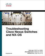
The command show ip eigrp topology [network-prefix/prefix-length] [active | all-links] displays the EIGRP topology table. Using the optional active keyword displays prefixes that are in an active state, and the all-links keyword displays all paths (including those that are not successors or feasible successors). Figure 7-2 displays the topology table for NX-1 from Figure 7-1.
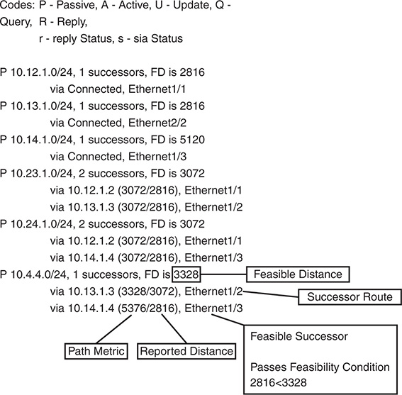
Figure 7-2 EIGRP Topology Table
Upon examining the network 10.4.4.0/24, notice that NX-1 calculates a FD of 3,328 for the successor route. The successor (upstream router) advertises the successor route with a reported distance (RD) of 3,072. The second path entry has a metric of 5,376 and has an RD of 2,816. Because 2,816 is less than 3,072, the second entry passes the feasibility condition and classifies the second entry as the feasible successor for prefix.
The 10.4.4.0/24 route is Passive (P), which means that the topology is stable. During a topology change, routes go into an Active (A) state when computing a new path.
Path Metric Calculation
Metric calculation is a critical component for any routing protocol. EIGRP uses multiple factors to calculate the metric for a path. Metric calculation uses bandwidth and delay by default, but can include interface load and reliability too.
The path metric formula shown in Figure 7-3 is described in RFC 7868, which explains EIGRP.
Figure 7-3 EIGRP Metric Formula
EIGRP uses K values to define which coefficients the formula uses and the associated impact with that coefficient when calculating the metric. A common misconception is that the K values directly apply to bandwidth, load, delay, or reliability; this is not accurate. For example, K1 and K2 both reference bandwidth (BW).
BW represents the slowest link in the path scaled to a 10 Gigabit per second link (107). Link speed is collected from the configured interface bandwidth on an interface. Delay is the total measure of delay in the path measured in tenths of microseconds (μs).
The EIGRP formula is based off the IGRP metric formula, except the output is multiplied by 256 to change the metric from 24 bits to 32 bits. Taking these definitions into consideration, the formula for EIGRP is shown in Figure 7-4.

Figure 7-4 EIGRP RFC Formula with Definitions
By default, K1 and K3 have a value of 1, and K2, K4, and K5 are set to 0. Figure 7-5 places default K values into the formula and then shows a streamlined version of the formula.

Figure 7-5 EIGRP Formula with Default K Values
Note
EIGRP includes a second formula to address high-speed interfaces called EIGRP wide metrics, which add a sixth K value. EIGRP wide metrics is explained later in the chapter.
The EIGRP update packet includes path attributes associated with each prefix. The EIGRP path attributes can include hop count, cumulative delay, minimum bandwidth link speed, and reported distance. The attributes are updated at each hop along the way, allowing each router to independently identify the shortest path.
Table 7-2 shows some of the common network types, link speeds, delays, and EIGRP metrics using the streamlined formula from Figure 7-5.
Table 7-2 Default EIGRP Interface Metrics
Interface Type |
Link Speed (Kbps) |
Delay |
Metric |
Serial |
64 |
20,000 μs |
40,512,000 |
T1 |
1,544 |
20,000 μs |
2,170,031 |
Ethernet |
10,000 |
1,000 μs |
281,600 |
FastEthernet |
100,000 |
100 μs |
28,160 |
GigabitEthernet |
1,000,000 |
10 μs |
2,816 |
10 GigabitEthernet |
10,000,000 |
10 μs |
512 |
Note
Notice how the delay is the same between Serial and T1 interfaces, so the only granularity is the link speed. In addition, there is not a differentiation of delay between the Gigabit Ethernet and 10 Gigabit Ethernet interfaces.
Using the topology from Figure 7-1, the metric from NX-1 for the 10.4.4.0/24 network is calculated using the formula in Figure 7-5. The link speed for both Nexus switches is 1 Gbps, and the total delay is 30 μs (10 μs for the 10.4.4.0/24 link, 10 μs for the 10.34.1.0/24 link, and 10 μs for the 10.13.1.0/24 link to NX-3).
The EIGRP metric for a specific prefix is queried directly from EIGRP’s topology table with the command show ip eigrp topology network/prefix-length. Example 7-1 shows NX-1’s topology table output for the 10.4.4.0/24 network. Notice that the output includes the successor route, any feasible successor paths, and the EIGRP state for the prefix. Each path contains the EIGRP attributes minimum bandwidth, total delay, interface reliability, load, and hop count.
Example 7-1 EIGRP Topology for a Specific Prefix
IP-EIGRP (AS 1): Topology entry for 10.4.4.0/24
State is Passive, Query origin flag is 1, 1 Successor(s), FD is 3328
Routing Descriptor Blocks:
10.13.1.3 (Ethernet1/2), from 10.13.1.3, Send flag is 0x0
Composite metric is (3328/3072), Route is Internal
Vector metric:
Load is 1/255
Minimum MTU is 1500
Hop count is 2
Internal tag is 0
10.14.1.4 (Ethernet1/3), from 10.14.1.4, Send flag is 0x0
Composite metric is (5376/2816), Route is Internal
Vector metric:
Load is 1/255
Minimum MTU is 1500
Hop count is 1
Internal tag is 0
Note
The EIGRP topology table maintains other paths besides the successor and feasible successor. The command show ip eigrp topology all-links displays the other ones.
EIGRP Communication
EIGRP uses five packet types to communicate with other routers, as shown in Table 7-3. EIGRP uses its own IP protocol number (88), and uses multicast packets where possible and unicast packets when necessary. Communication between EIGRP devices is accomplished using the multicast group address of 224.0.0.10 or MAC address of 01:00:5e:00:00:0a when possible.
Type |
Packet Name |
Function |
1 |
Hello |
Used for discovery of EIGRP neighbors, and for detection of when a neighbor is no longer available |
2 |
Acknowledgement (ACK) |
Packets sent to the originating router for any other EIGRP packet containing a nonzero sequence number |
3 |
Update |
Packets used to transmit routing and reachability information with other EIGRP routers |
4 |
Query |
Packets sent out searching for another path during convergence |
5 |
Reply |
Packets that are sent in response of a query packet |
EIGRP uses the Reliable Transport Protocol (RTP) to ensure that packets are delivered in order and that routers receive specific packets. A sequence number is included in all of the EIGRP packets. A sequence value of zero does not require a response from the receiving EIGRP router; all other values require an Acknowledgement packet that includes the original sequence number.
Ensuring that packets are received makes the transport method reliable. All Updates, Queries, and Reply packets are deemed reliable, whereas Hello and Acknowledgement packets do not require acknowledgement and could be unreliable.
If the originating router does not receive an acknowledgement packet from the neighbor before the retransmit timeout expires, it notifies the nonresponsive router to stop processing its multicast packets. The originating router sends all traffic via unicast, until the neighbor is fully synchronized. Upon complete synchronization, the originating router notifies the destination router to start processing multicast packets again. All unicast packets require acknowledgement. EIGRP will retry up to 16 times for each packet that requires confirmation and will reset the neighbor relationship when the neighbor reaches the retry limit of 16.
Baseline EIGRP Configuration
The EIGRP configuration process on a NX-OS switch requires configuration under the EIGRP process and under the interface configuration submode. The following steps explain the process for configuring EIGRP on a NX-OS device.
Step 1. Enable the EIGRP feature. The EIGRP feature must be enabled with the global configuration command feature eigrp.
Step 2. Define an EIGRP process tag. The EIGRP process must be defined with the global configuration command router eigrp process-tag. The process-tag can be up to 20 alphanumeric characters in length.
Step 3. Define the Router-ID (optional). The Router-ID (RID) is a 32-bit unique number that identifies an EIGRP router. EIGRP uses the RID as a loop prevention mechanism. The RID can be set manually or dynamically, but should be unique for each EIGRP process. The command router-id router-id is used to statically set the RID.
If a RID is not manually configured, the Loopback 0 IP address is always preferred. If the Loopback 0 does not exist, NX-OS selects the IP address for the first loopback interface in the configuration. If no loopback interfaces exist, NX-OS selects the IP address for the first physical interface in the configuration.
Step 4. Define the address family. EIGRP supports IPv4 and IPv6 address-families under the same EIGRP process. Therefore, the address-family should be defined with the command address-family [ipv4 | ipv6] unicast.
This step is optional for exchanging IPv4 addresses on Nexus switches.
Step 5. Define the Autonomous System Number (ASN) for the EIGRP process. The autonomous system must be defined for the EIGRP process with the command autonomous-system as-number.
This step is optional if the EIGRP process tag is only numeric and matches the ASN used by the EIGRP process.
Step 6. Enable EIGRP on interfaces. The interface that EIGRP is enabled on is selected with the command interface interface-id. The EIGRP process is then enabled on that interface with the command ip router eigrp process-tag.
Note
Unlike IOS devices, enabling EIGRP on an interface advertises any secondary connected network into the topology table.
The configuration in Example 7-2 enables EIGRP only on interfaces Ethernet1/1, VLAN 10, and Loopback 0.
Example 7-2 Baseline EIGRP Configuration
NX-1(config)# feature eigrp
NX-1(config)# router eigrp NXOS
17:10:19 NX-1 %$ VDC-1 %$ eigrp[27525]: EIGRP-5-HA_INFO: EIGRP HA info msg - SYSMGR_SUPSTATE_ACTIVE
NX-1(config-router)# autonomous-system 12
NX-1(config-router)# address-family ipv4 unicast
NX-1(config-router-af)# interface Ethernet1/1
NX-1(config-if)# ip router eigrp NXOS
NX-1(config-if)# interface vlan10
NX-1(config-if)# ip router eigrp NXOS
NX-1(config-if)# interface loopback0
NX-1(config-if)# ip router eigrp NXOS
17:10:19 NX-1 %$ VDC-1 %$ %EIGRP-5-NBRCHANGE_DUAL: eigrp-NXOS [27525] (default-base) IP-EIGRP(0) 123: Neighbor 10.12.1.2 (Ethernet1/2) is up: new adjacency
Troubleshooting EIGRP Neighbor Adjacency
EIGRP requires a neighbor relationship to form before routes are processed and added to the Routing Information Base (RIB) (a.k.a. routing table). The neighbor adjacency table is vital for tracking neighbor status and the updates sent to each neighbor. This section explains the process for troubleshooting EIGRP neighbor adjacencies on NX-OS switches.
Figure 7-6 provides a simple topology with two Nexus switches that are used to explain how to troubleshoot EIGRP adjacency problems.
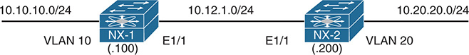
Figure 7-6 Topology with Two NX-OS Switches
The first step is to verify devices that have successfully established an EIGRP adjacency with the command show ip eigrp neighbors [detail] [interface-id | neighbor-ip-address | vrf {vrf-name | all}]. Example 7-3 demonstrates the command being run on NX-1.
Example 7-3 Display of EIGRP Neighbors
IP-EIGRP neighbors for process 12 VRF default
H Address Interface Hold Uptime SRTT RTO Q Seq
(sec) (ms) Cnt Num
0 10.12.1.200 Eth1/1 14 00:09:45 1 50 0 17
Table 7-4 provides a brief explanation to the key fields shown in Example 7-3.
Table 7-4 EIGRP Neighbor Columns
Field |
Description |
Address |
IP address of the EIGRP neighbor |
Interface |
Interface the neighbor was detected on |
Holdtime |
Time left to receive a packet from this neighbor to ensure it is still alive |
SRTT |
Time for a packet to be sent to a neighbor, and a reply from that neighbor received in milliseconds |
RTO |
Timeout for retransmission (Waiting for ACK) |
Q Cnt |
Number of packets (update/query/reply) in queue for sending |
Seq Num |
Sequence number that was last received from this router |
Besides enabling EIGRP on the network interfaces of an NX-OS device, the following parameters must match for the two routers to become neighbors:
Interfaces must be Active
Connectivity between devices must exist using the primary subnet
Autonomous system numbers (ASN) matches
Metric formula K values
Hello and Hold timers support timely communication
Authentication parameters
Verification of Active Interfaces
Upon configuring EIGRP, it is a good practice to verify that only the intended interfaces are running EIGRP. The command show ip eigrp interface [brief | interface-id] [vrf {vrf-name | all}] displays the active EIGRP interfaces. Appending the optional brief keyword shrinks the amount of content shown to what is displayed in Example 7-4.
Example 7-4 Display of Active EIGRP Interfaces
IP-EIGRP interfaces for process 123 VRF default
Xmit Queue Mean Pacing Time Multicast Pending
Interface Peers Un/Reliable SRTT Un/Reliable Flow Timer Routes
Eth1/1 1 0/0 6 0/0 50 0
Lo0 0 0/0 0 0/0 0 0
Vlan10 0 0/0 0 0/0 0 0
Table 7-5 provides a brief explanation of the key fields shown with the EIGRP interfaces.
Table 7-5 EIGRP Interface Fields
Field |
Description |
Interface |
Interfaces running EIGRP. |
Peers |
Number of peers detected on that interface. |
Xmt Queue Un/Reliable |
Number of unreliable/reliable packets remaining in the transmit queue. A value of zero is an indication of a stable network. |
Mean SRTT |
Average time for a packet to be sent to a neighbor, and a reply from that neighbor received in milliseconds. |
Pacing Time Un/Reliable |
Used to determine when EIGRP packets should be sent out of the interface (for unreliable and reliable packets). |
Multicast Flow Timer |
Maximum time (seconds) that the router sent multicast packets. |
Pending Routes |
Number of routes in the transmit queue that need to be sent. |
Passive Interface
Some network topologies require advertising a network segment into EIGRP, but need to prevent neighbors from forming adjacencies on that segment. Example scenarios involve advertising access layer networks in a campus topology.
To illustrate how this can cause problems, NX-1 and NX-2 cannot establish an EIGRP adjacency. Viewing the EIGRP interfaces on both switches and the peering link E1/1 is not displayed as expected in Example 7-5.
Example 7-5 Identification of Active EIGRP Interfaces
IP-EIGRP interfaces for process 12 VRF default
Xmit Queue Mean Pacing Time Multicast Pending
Interface Peers Un/Reliable SRTT Un/Reliable Flow Timer Routes
Vlan10 0 0/0 0 0/0 0 0
IP-EIGRP interfaces for process 12 VRF default
Xmit Queue Mean Pacing Time Multicast Pending
Interface Peers Un/Reliable SRTT Un/Reliable Flow Timer Routes
Lo0 0 0/0 0 0/0 0 0
Vlan20 0 0/0 0 0/0 0 0
A passive interface is not displayed when displaying the EIGRP interfaces as explained in the previous section. Examining the EIGRP process with the command show ip eigrp [process-tag] provides a count of active and passive interfaces as seen in Example 7-6.
Example 7-6 Viewing EIGRP Passive Interfaces
Number of EIGRP interfaces: 1 (0 loopbacks)
The configuration must then be examined for the following:
The interface parameter command ip passive-interface eigrp process-tag, which makes only that interface passive.
The global EIGRP configuration command passive-interface default, which makes all interfaces under that EIGRP process passive. The interface parameter command no ip passive-interface eigrp process-tag takes precedence over the global command and makes that interface active.
Example 7-7 displays the configuration on NX-1 and NX-2 that prevents the two Nexus switches from forming an EIGRP adjacency. The Ethernet1/1 interfaces must be active on both switches for an adjacency to form. The command no ip passive-interface eigrp NXOS should be moved to Interface E1/1 on NX-1, and the command ip passive-interface eigrp NXOS should be moved from E1/1 to Vlan20 on NX-2.
Example 7-7 EIGRP Configuration with Passive Interfaces
autonomous-system 12
interface Vlan10
ip router eigrp NXOS
interface loopback0
ip router eigrp NXOS
interface Ethernet1/1
ip router eigrp NXOS
autonomous-system 12
address-family ipv4 unicast
interface Vlan20
ip router eigrp NXOS
interface loopback0
ip router eigrp NXOS
interface Ethernet1/1
ip router eigrp NXOS
ip passive-interface eigrp NXOS
Note
In addition to placing an interface into a passive state, an interface can have EIGRP temporarily shut down with the command ip eigrp process-tag shutdown. This disables EIGRP on that interface while leaving EIGRP configuration on that interface.
Verification of EIGRP Packets
A vital step in troubleshooting EIGRP adjacency issues is to ensure that a device is transmitting or receiving EIGRP network traffic. The command show ip eigrp traffic displays a high-level summary of packet types that have been sent or received from a device. Example 7-8 shows the use of this command.
Example 7-8 EIGRP Traffic Statistics
IP-EIGRP Traffic Statistics for AS 12 VRF default
Hellos sent/received: 1486/623
Updates sent/received: 13/8
Queries sent/received: 0/0
Replies sent/received: 0/0
Acks sent/received: 6/8
Input queue high water mark 1, 0 drops
SIA-Queries sent/received: 0/0
SIA-Replies sent/received: 0/0
Hello Process ID: (no process)
PDM Process ID: (no process)
Debug functionality is used to acquire granularity on the receipt or transmission of a packet. The command debug ip eigrp packets [siaquery | siareply | hello | query | reply | request | update | verbose] enables debug functionality for the type of packet that is selected. Example 7-9 displays the use of the EIGRP packet debugs.
Example 7-9 EIGRP Packet Debugs
03:58:18.814582 eigrp: NXOS [26942] nbr 10.10.10.10
03:58:18.814613 eigrp: NXOS [26942] AS 12, Flags 0x0, Seq 0/0idbQ 0/0
03:58:18.814618 eigrp: NXOS [26942] iidbQ un/rely 0/0
03:58:18.814623 eigrp: NXOS [26942] peerQ un/rely 0/0
03:58:18.965326 eigrp: NXOS [26942] EIGRP: Received HELLO on Ethernet1/1
03:58:18.965415 eigrp: NXOS [26942] nbr 10.12.1.200
03:58:18.965424 eigrp: NXOS [26942] AS 12, Flags 0x0, Seq 0/0idbQ 0/0
03:58:18.965430 eigrp: NXOS [26942] iidbQ un/rely 0/0
03:58:18.965435 eigrp: NXOS [26942] peerQ un/rely 0/0
03:58:20.244286 eigrp: NXOS [26942] EIGRP: Sending HELLO on Vlan10
03:58:20.244304 eigrp: NXOS [26942] AS 12, Flags 0x0, Seq 0/0idbQ 0/0
03:58:20.244310 eigrp: NXOS [26942] iidbQ un/rely 0/0
03:58:21.273574 eigrp: NXOS [26942] EIGRP: Sending HELLO on Ethernet1/1
03:58:21.273651 eigrp: NXOS [26942] AS 12, Flags 0x0, Seq 0/0idbQ 0/0
03:58:21.273660 eigrp: NXOS [26942] iidbQ un/rely 0/0
Performing EIGRP debugs shows only the packets that have reached the supervisor CPU. If packets are not displayed in the debugs, further troubleshooting must be taken by examining quality of service (QoS) policies, access control list (ACL), control plane policing (CoPP), or just verification of the packet leaving or entering an interface.
QoS policies may or may not be deployed on an interface. If they are deployed, the policy-map must be examined for any dropped packets, which must then be referenced to a class-map that matches the EIGRP routing protocol. The same logic applies to CoPP policies because they are based on QoS settings.
Example 7-10 displays the process for checking the CoPP policy with the following logic:
Examine the CoPP policy with the command show running-config copp all. This displays the relevant policy-map name, classes defined, and the police rate for each class.
Investigate the class-maps to identify the conditional matches for that class-map.
After the class-map has been verified, examine the policy-map drops for that class with the command show policy-map interface control-plane.
Example 7-10 Verification of CoPP for EIGRP
match access-group name copp-system-p-acl-bgp
match access-group name copp-system-p-acl-rip
match access-group name copp-system-p-acl-vpc
match access-group name copp-system-p-acl-bgp6
match access-group name copp-system-p-acl-lisp
match access-group name copp-system-p-acl-ospf
match access-group name copp-system-p-acl-rip6
match access-group name copp-system-p-acl-rise
match access-group name copp-system-p-acl-ospf6
match access-group name copp-system-p-acl-rise6
match access-group name copp-system-p-acl-eigrp6
match access-group name copp-system-p-acl-otv-as
match access-group name copp-system-p-acl-mac-l2pt
match access-group name copp-system-p-acl-mpls-ldp
match access-group name copp-system-p-acl-mpls-rsvp
match access-group name copp-system-p-acl-mac-l3-isis
match access-group name copp-system-p-acl-mac-otv-isis
match access-group name copp-system-p-acl-mac-fabricpath-isis
..
policy-map type control-plane copp-system-p-policy-strict
class copp-system-p-class-critical
set cos 7
police cir 36000 kbps bc 250 ms conform transmit violate drop
ip access-list copp-system-p-acl-eigrp
10 permit eigrp any any
service-policy input copp-system-p-policy-strict
class-map copp-system-p-class-critical (match-any)
..
module 1:
conformed 1623702 bytes,
5-min offered rate 995 bytes/sec
peak rate 1008 bytes/sec at Tues 16:08:39 2018
5-min violate rate 0 bytes/sec
peak rate 0 bytes/sec
Note
This CoPP policy was taken from a Nexus 7000 switch; the policy-name and class-maps may vary depending on the platform.
The next phase is to identify if packets were transmitted or received on an interface. This technique involves creating a specific access control entity (ACE) for the EIGRP protocol. The ACE for EIGRP should appear before any other ambiguous ACE entries to ensure a proper count. The ACL configuration command statistics per-entry is required to display the specific hits that are encountered per ACE.
Example 7-11 demonstrates the configuration of an ACL to detect EIGRP traffic on the Ethernet1/1 interface. Notice that the ACL includes a permit ip any any command to allow all traffic to pass through this interface. Failing to do so could result in the loss of traffic.
Example 7-11 Verification of EIGRP Packets with ACL
NX-1(config)# ip access-list EIGRP
NX-1(config-acl)# permit eigrp any any
NX-1(config-acl)# permit icmp any any
NX-1(config-acl)# permit ip any any
NX-1(config-acl)# statistics per-entry
NX-1(config-acl)# interface e1/1
NX-1(config-if)# ip access-group EIGRP in
IP access list EIGRP
statistics per-entry
10 permit eigrp any any [match=108]
20 permit icmp any any [match=5]
30 permit ip any any [match=1055]
Example 7-11 uses an Ethernet interface, which generally indicates a one-to-one relationship, but on multi-access interfaces like Switched Virtual Interfaces (SVI) (a.k.a. Interface VLANs) the neighbor may need to be specified in a specific ACE.
Example 7-12 displays the configuration for an ACL that is placed on a SVI with an ACE entry for the neighbor 10.12.100.200. EIGRP packets from other neighbors are collected with the second entry, line 20.
Example 7-12 Granular Verification of EIGRP Packets with ACL
statistics per-entry
permit eigrp 10.12.100.200/32 any any
permit eigrp any any
permit icmp any any
permit ip any any
interface vlan 10
ip access-group EIGRP in
IP access list EIGRP
statistics per-entry
30 permit icmp any any [match=0]
40 permit ip any any [match=5]
An alternative to using an ACL is to use the built-in NX-OS Ethanalyzer to capture the EIGRP packets. Example 7-13 demonstrates the command syntax. The optional detail keyword is used to view the contents of the packets.
Example 7-13 Verification of EIGRP Packets Using Ethanalyzer
Capturing on inband
2017-09-03 04:21:12.688751 10.12.1.2 -> 224.0.0.10 EIGRP Hello
2017-09-03 04:21:12.690573 10.12.1.1 -> 224.0.0.10 EIGRP Hello
2017-09-03 04:21:12.701393 10.12.1.2 -> 224.0.0.10 EIGRP Hello
2017-09-03 04:21:12.705344 10.12.1.2 -> 10.12.1.1 EIGRP Update
2017-09-03 04:21:12.705344 10.12.1.2 -> 10.12.1.1 EIGRP Update
Connectivity Must Exist Using the Primary Subnet
EIGRP routers must be able to communicate with their peer routers by using the network associated to the primary IP address. EIGRP adjacency is formed only using primary IP addresses; it cannot form an adjacency using secondary IP addresses. The subnet mask was changed on NX-2 from 10.12.1.200/24 to 10.12.1.200/25 for this section. This places NX-2 in the 10.12.1.128/25 network from NX-1 (10.12.1.100).
Example 7-14 demonstrates that NX-1 detects NX-2 and registers it as a neighbor, whereas NX-2 does not detect NX-1.
Example 7-14 NX-1 Detects NX-2 as Neighbor
IP-EIGRP neighbors for process 12 VRF default
H Address Interface Hold Uptime SRTT RTO Q Seq
(sec) (ms) Cnt Num
0 10.12.1.200 Eth1/1 13 00:00:10 1 5000 1 0
IP-EIGRP neighbors for process 12 VRF default
In addition, NX-1 keeps changing the neighbor state for NX-2 (10.12.1.200) after a retry limit was exceeded, as shown in Example 7-15.
Example 7-15 EIGRP Adjacency Dropping due to Retry Limit
13:28:06 NX-1 %$ VDC-1 %$ %EIGRP-5-NBRCHANGE_DUAL: eigrp-NXOS [26809] (default-base) IP-EIGRP(0) 12: Neighbor 10.12.1.200 (Ethernet1/1) is down: retry limit exceeded
13:28:09 NX-1 %$ VDC-1 %$ %EIGRP-5-NBRCHANGE_DUAL: eigrp-NXOS [26809] (default-base) IP-EIGRP(0) 12: Neighbor 10.12.1.200 (Ethernet1/1) is up: new adjacency
21:19:00 NX-1 %$ VDC-1 %$ %EIGRP-5-NBRCHANGE_DUAL: eigrp-NXOS [26809] (default-base) IP-EIGRP(0) 123: Neighbor 10.12.1.200 (Ethernet1/1) is down: retry limit exceeded
21:19:00 NX-1 %$ VDC-1 %$ %EIGRP-5-NBRCHANGE_DUAL: eigrp-NXOS [26809] (default-base) IP-EIGRP(0) 123: Neighbor 10.12.1.200 (Ethernet1/1) is up: new adjacency
Note
NX-OS does not provide the syslog message “is blocked: not on common subnet” that is included with IOS routers.
Remember that EIGRP will retry up to 16 times for each packet that requires confirmation, and it will reset the neighbor relationship when the neighbor reaches the retry limit of 16. The actual retry values are examined on NX-OS by using the command show ip eigrp neighbor detail, as demonstrated in Example 7-16.
Example 7-16 Viewing EIGRP Retry Values for Neighbors
IP-EIGRP neighbors for process 12 VRF default
H Address Interface Hold Uptime SRTT RTO Q Seq
(sec) (ms) Cnt Num
0 10.12.1.200 Eth1/1 14 00:01:12 1 5000 1 0
Version 8.0/1.2, Retrans: 15, Retries: 15, BFD state: N/A, Waiting for Init,
Waiting for Init Ack
UPDATE seq 13 ser 0-0 Sent 78084 Init Sequenced
NX-1# show ip eigrp neighbors detail
IP-EIGRP neighbors for process 12 VRF default
H Address Interface Hold Uptime SRTT RTO Q Seq
(sec) (ms) Cnt Num
0 10.12.1.200 Eth1/1 13 00:01:19 1 5000 1 0
Version 8.0/1.2, Retrans: 16, Retries: 16, BFD state: N/A, Waiting for Init,
Waiting for Init Ack
UPDATE seq 13 ser 0-0 Sent 79295 Init Sequenced
The next step is to try to ping the primary IP address between nodes, as shown in Example 7-17.
Example 7-17 Verify Connectivity Between Primary Subnets
PING 10.12.1.200 (10.12.1.200): 56 data bytes
Request 0 timed out
Request 1 timed out
Request 2 timed out
Request 3 timed out
Request 4 timed out
--- 10.12.1.200 ping statistics ---
5 packets transmitted, 0 packets received, 100.00% packet loss
PING 10.12.1.100 (10.12.1.100): 56 data bytes
ping: sendto 10.12.1.100 64 chars, No route to host
Request 0 timed out
ping: sendto 10.12.1.100 64 chars, No route to host
Request 1 timed out
ping: sendto 10.12.1.100 64 chars, No route to host
Request 2 timed out
ping: sendto 10.12.1.100 64 chars, No route to host
Request 3 timed out
ping: sendto 10.12.1.100 64 chars, No route to host
Request 4 timed out
NX-1 cannot ping NX-2, and NX-2 cannot ping NX-1 because it does not have a route to the host. This also means that NX-1 might have been able to send the packets to NX-2, but NX-2 did not have a route to send the ICMP response.
Example 7-18 displays the routing table on NX-1 and NX-2 to help locate the reason.
Example 7-18 NX-1 and NX-2 Routing Table for Adjacency
IP Route Table for VRF "default"
'*' denotes best ucast next-hop
'**' denotes best mcast next-hop
'[x/y]' denotes [preference/metric]
'%<string>' in via output denotes VRF <string>
10.12.1.200/32, ubest/mbest: 1/0, attached
*via 10.12.1.200, Eth1/1, [250/0], 00:30:29, am
IP Route Table for VRF "default"
'*' denotes best ucast next-hop
'**' denotes best mcast next-hop
'[x/y]' denotes [preference/metric]
'%<string>' in via output denotes VRF <string>
Route not found
At this point, check the IP address configuration on both devices. This should result in the mismatch of prefix-length for the subnet mask. Correcting this allows for the EIGRP devices to communicate properly.
EIGRP ASN Mismatch
EIGRP requires that the ASN match in the EIGRP Hello packets to form an adjacency. Problems can occur on Nexus switches because EIGRP uses the number specified in the process tag as the ASN by default. This mentality aligns with the Classic mode configuration of EIGRP on IOS routers.
If an ASN is specified within the EIGRP configuration, that value is used in lieu of the number used to identify the EIGRP process. If the EIGRP process tag is alphanumeric, and an ASN is not specified, it assumes an ASN of 0, which indicates that instance is in a shutdown state.
Example 7-19 displays a configuration that might be confusing to junior network engineers. Is the EIGRP ASN 12 or 1234?
Example 7-19 Confusing EIGRP ASN Configuration
router eigrp 12
interface Ethernet1/1
ip router eigrp 12
Unfortunately, no debugs or log messages are provided if the EIGRP ASNs are mismatched. Check the EIGRP ASN on both sides to verify that it is the same.
The ASN for an EIGRP instance is found by examining the EIGRP protocol with the command show ip eigrp, which is listed beside the router-id. The ASN is also displayed when viewing the EIGRP interfaces with the command show ip eigrp interfaces brief.
Example 7-20 displays how the AS is viewed on a Nexus switch.
Example 7-20 Identifying the EIGRP AS
Process-tag: 12
Instance Number: 1
Status: running
IP-EIGRP interfaces for process 1234 VRF default
Xmit Queue Mean Pacing Time Multicast Pending
Interface Peers Un/Reliable SRTT Un/Reliable Flow Timer Routes
Eth1/1 0 0/0 0 0/0 0 0
Lo0 0 0/0 0 0/0 0 0
Vlan10 0 0/0 0 0/0 0 0
Note
Specifying the AS in the EIGRP configuration removes any potential for confusion by network engineers of all skill level. This is considered a best practice.
Mismatch K Values
EIGRP uses K values to define which factors that the best path formula uses. To ensure a consistent routing logic and prevent routing loops from forming, all EIGRP neighbors must use the same K values. The K values are included as part of the EIGRP Hello packets.
Example 7-21 displays the syslog message that indicates a mismatch of K values. The K values are identified on the local router by looking at the EIGRP process with the command show ip eigrp.
Example 7-21 Indication of EIGRP K Values Mismatch
04:11:37 NX-1 %$ VDC-1 %$ last message repeated 3 times
04:11:37 NX-1 %$ VDC-1 %$ %EIGRP-5-NBRCHANGE_DUAL: eigrp-NXOS [30489] (default-base) IP-EIGRP(0) 12: Neighbor 10.12.1.200 (Ethernet1/1) is down: Interface Goodbye received
Process-tag: NXOS
Instance Number: 1
Status: running
none
The K values on Nexus switches are configured with the command metric weights TOS K1 K2 K3 K4 K5[K6] under the EIGRP process. The K6 value is optional unless EIGRP wide metrics are configured. TOS is not used and should be set to zero. Example 7-22 displays an EIGRP configuration with custom K values.
Example 7-22 EIGRP Configuration with Custom K Values
autonomous-system 12
Problems with Hello and Hold Timers
A secondary function to the EIGRP Hello packets is to ensure that EIGRP neighbors are still healthy and available. EIGRP Hello packets are sent out in intervals referred to as the Hello Timer. The default EIGRP Hello timer is 5 seconds by default on Nexus switches.
EIGRP uses a second timer called the hold time, which is the amount of time EIGRP deems the router reachable and functioning. The hold time value defaults to three times the Hello interval. The default value is 15 seconds, and 180 seconds for slow-speed interfaces. The hold time decrements, and upon receipt of a Hello packet, the hold time resets and restarts the countdown. If the hold time reaches zero, EIGRP declares the neighbor unreachable and notifies the DUAL algorithm of a topology change.
If the EIGRP Hello timer is greater than the Hold timer on the other EIGRP neighbor, the session will continuously flap. Example 7-23 demonstrates NX-1 periodically resetting the adjacency with NX-2 because of the holding time expiring on NX-1.
Example 7-23 EIGRP Adjacency Failure due to Holding Timer
03:11:35 NX-1 %$ VDC-1 %$ %EIGRP-5-NBRCHANGE_DUAL: eigrp-NXOS [30489] (default-base) IP-EIGRP(0) 12: Neighbor 10.12.1.200 (Ethernet1/1) is down: holding time expired
03:11:39 NX-1 %$ VDC-1 %$ %EIGRP-5-NBRCHANGE_DUAL: eigrp-NXOS [30489] (default-base) IP-EIGRP(0) 12: Neighbor 10.12.1.200 (Ethernet1/1) is up: new adjacency
03:11:54 NX-1 %$ VDC-1 %$ %EIGRP-5-NBRCHANGE_DUAL: eigrp-NXOS [30489] (default-base) IP-EIGRP(0) 12: Neighbor 10.12.1.200 (Ethernet1/1) is down: holding time expired
03:11:59 NX-1 %$ VDC-1 %$ %EIGRP-5-NBRCHANGE_DUAL: eigrp-NXOS [30489] (default-base) IP-EIGRP(0) 12: Neighbor 10.12.1.200 (Ethernet1/1) is up: new adjacency
03:11:35 NX-2 %$ VDC-1 %$ %EIGRP-5-NBRCHANGE_DUAL: eigrp-NXOS [26807] (default-base) IP-EIGRP(0) 12: Neighbor 10.12.1.100 (Ethernet1/1) is down: Interface Goodbye received
03:11:39 NX-2 %$ VDC-1 %$ %EIGRP-5-NBRCHANGE_DUAL: eigrp-NXOS [26807] (default-base) IP-EIGRP(0) 12: Neighbor 10.12.1.100 (Ethernet1/1) is up: new adjacency
03:11:54 NX-2 %$ VDC-1 %$ %EIGRP-5-NBRCHANGE_DUAL: eigrp-NXOS [26807] (default-base) IP-EIGRP(0) 12: Neighbor 10.12.1.100 (Ethernet1/1) is down: Interface Goodbye received
03:11:59 NX-2 %$ VDC-1 %$ %EIGRP-5-NBRCHANGE_DUAL: eigrp-NXOS [26807] (default-base) IP-EIGRP(0) 12: Neighbor 10.12.1.100 (Ethernet1/1) is up: new adjacency
The EIGRP Hello and Hold timers for an interface are seen with the command show ip eigrp interface [interface-id] [vrf {vrf-name | all}]. The optional brief keyword cannot be used to view the timers. Example 7-24 displays sample output for NX-1 and NX-2.
Example 7-24 Verification of EIGRP Hello and Hold Timers
Xmit Queue Mean Pacing Time Multicast Pending
Interface Peers Un/Reliable SRTT Un/Reliable Flow Timer Routes
Eth1/1 1 0/0 1 0/0 50 0
Hello interval is 5 sec
Holdtime interval is 15 sec
Next xmit serial <none>
NX-2# show ip eigrp interfaces
Xmit Queue Mean Pacing Time Multicast Pending
Interface Peers Un/Reliable SRTT Un/Reliable Flow Timer Routes
Eth1/1 1 0/0 3 0/0 50 0
Hello interval is 120 sec
Holdtime interval is 15 sec
Next xmit serial <none>
NX-2 is displaying a Hello timer of 120 seconds which exceeds NX-1’s Hold timer of 15 seconds which is the reason that NX-1 keeps tearing down the EIGRP adjacency.
Example 7-25 verifies that the Hello interval was modified with the interface command ip hello-interval eigrp process-tag hello-time. Changing the Hello time back to the default value or a value less than 15 seconds (NX-1’s Hold timer) allows the switches to form an adjacency.
Example 7-25 EIGRP Configuration with Modified Hello Timer
autonomous-system 12
address-family ipv4 unicast
interface Ethernet1/1
ip router eigrp NXOS
ip hello-interval eigrp NXOS 120
Note
The EIGRP interface Hold timer is modified with the command ip hold-time eigrp process-tag hold-time.
EIGRP Authentication Issues
Authentication is a mechanism for ensuring that only authorized EIGRP devices are eligible to become EIGRP neighbors. A precomputed password hash is included with all EIGRP packets, and the receiving router decrypts the hash. If the passwords do not match, the router discards the packet; thereby preventing an adjacency from forming.
Unfortunately, no debugs or log messages are provided if there is a mismatch in authentication enablement or password inconsistency. The EIGRP authentication needs to be verified on both devices to ensure that it is enabled on both sides and the parameters are the same.
If authentication is explicitly configured on an interface, the status is displayed underneath the EIGRP interfaces as shown in Example 7-26. Notice that authentication only appears to be enabled on Ethernet1/1.
Example 7-26 Viewing EIGRP Authentication on Interfaces
Hello interval is 5 sec
Holdtime interval is 15 sec
Next xmit serial <none>
Un/reliable mcasts: 0/55 Un/reliable ucasts: 85/65
Mcast exceptions: 0 CR packets: 0 ACKs suppressed: 20
Retransmissions sent: 8 Out-of-sequence rcvd: 0
Vlan20 0 0/0 0 0/0 0 0
EIGRP encrypts the password using an MD5 using the keychain function. Keychains allow the configuration of multiple passwords and sequences that can have the validity period set so that passwords could be rotated. When using time-based keychains, it is important that the Nexus switches time is synchronized with NTP and that some overlap of time is provided between key iterations.
The hash is composed of the key number and a password. EIGRP authentication does not encrypt the entire EIGRP packet, just the password. The password is seen with the command show key chain [mode decrypt]. The optional keywords mode decrypt display the password in plain text between a pair of quotation marks, which is helpful to detect unwanted characters such as spaces. Example 7-27 displays how the keychain password is verified.
Example 7-27 Verification of Keychains
Key-Chain EIGRP
Key 1 -- text 7 "0802657d2a36"
accept lifetime (always valid) [active]
send lifetime (always valid) [active]
Key-Chain EIGRP
Key 1 -- text 0 "CISCO"
accept lifetime (always valid) [active]
send lifetime (always valid) [active]
Note
The hash does not match between EIGRP devices if the key number is different, even if the password is identical. So the key number and password must match.
Interface-Based EIGRP Authentication
Remediation of authentication-related issues requires that authentication is enabled on both neighbors’ interfaces and that the password is the same. The process for enabling EIGRP authentication on Nexus switches consist of the following steps:
Step 1. Create the keychain. The command key chain key-chain-name creates the local keychain.
Step 2. Identify the key sequence. The key sequence is specified with the command key key-number, where the key number can be anything from 0 to 2147483647.
Step 3. Specify the password. The pre-shared password is entered with the command key-string text. Steps 2 and 3 could be repeated as needed to accommodate multiple key strings.
Step 4. Identify the keychain for an interface. The keychain used by the interface must be specified with the command ip authentication key-chain eigrp process-tag key-chain-name.
Step 5. Enable authentication for an interface. Authentication is then enabled on the interface with the command ip authentication mode eigrp process-tag md5.
Example 7-28 demonstrates a sample configuration for EIGRP authentication on Ethernet1/1.
Example 7-28 EIGRP Interface Level Authentication
key 1
key-string CISCO
router eigrp NXOS
autonomous-system 12
authentication mode md5
interface Ethernet1/1
ip router eigrp NXOS
ip authentication key-chain eigrp NXOS EIGRP
ip authentication key-chain eigrp mode eigrp NXOS md5
Global EIGRP Authentication
At the time of this writing, if the EIGRP authentication is enabled globally, the authentication does not appear under all the interfaces with the command show ip eigrp interfaces.
Troubleshooting globally enabled authentication requires examination of the configuration. The main difference is that after the keychain is created, authentication is enabled with the following commands under the EIGRP process:
authentication mode md5
authentication key-chain key-chain-name
Example 7-29 displays the configuration for enabling authentication globally.
Example 7-29 EIGRP Process Level Authentication
key 1
key-string CISCO
router eigrp NXOS
autonomous-system 12
authentication mode md5
authentication key-chain EIGRP
address-family ipv4 unicast
Note
Interface-based authentication settings override any global EIGRP authentication settings.
Troubleshooting Path Selection and Missing Routes
Figure 7-7 provides a sample topology used to demonstrate how to troubleshoot various problems within the EIGRP protocol. All routers are connected with each other using 10 Gb links. NX-1 is advertising two networks, 10.1.1.0/24 and 10.11.11.0/24, while NX-6 is advertising the 10.6.6.0/24 network.
Figure 7-7 Topology to Demonstrate Path Selection
Example 7-30 displays a portion of NX-1 and NX-6’s routing table. Notice that two paths exist between NX-1 and NX-6 in both directions for the corresponding advertised network prefixes.
Example 7-30 NX-1’s Routing Table
*via 10.12.1.2, Eth1/1, [90/129088], 00:00:02, eigrp-NXOS, internal
*via 10.14.1.4, Eth1/2, [90/129088], 00:11:27, eigrp-NXOS, internal
*via 10.36.1.3, Eth1/1, [90/1280], 00:00:07, eigrp-NXOS, internal
*via 10.56.1.5, Eth1/2, [90/1280], 00:00:07, eigrp-NXOS, internal
10.11.11.0/24, ubest/mbest: 2/0
*via 10.36.1.3, Eth1/1, [90/1280], 00:00:07, eigrp-NXOS, internal
*via 10.56.1.5, Eth1/2, [90/1280], 00:00:07, eigrp-NXOS, internal
EIGRP routes that are installed into the RIB are seen with the command show ip route [eigrp]. The optional eigrp keyword only shows EIGRP learned routes. EIGRP routes are indicated by the eigrp-process-tag.
EIGRP routes originating within the autonomous system have an administrative distance (AD) of 90 and have the internal flag listed after the process-tag. Routes that originate from outside of the AS are external EIGRP routes. External EIGRP routes have an AD of 170, and have the external flag listed after the process-tag. Placing external EIGRP routes into the RIB with a higher AD acts as a loop prevention mechanism.
Example 7-31 displays the EIGRP routes from the sample topology in Figure 7-7. The metric for the selected route is the second number in brackets.
Example 7-31 Viewing EIGRP Routes on NX-1
'*' denotes best ucast next-hop
'**' denotes best mcast next-hop
'[x/y]' denotes [preference/metric]
10.1.1.0/24, ubest/mbest: 2/0
*via 10.36.1.3, Eth1/1, [90/1280], 00:00:07, eigrp-NXOS, internal
*via 10.56.1.5, Eth1/2, [90/1280], 00:00:07, eigrp-NXOS, internal
10.11.11.0/24, ubest/mbest: 2/0
*via 10.36.1.3, Eth1/1, [90/1280], 00:00:07, eigrp-NXOS, internal
*via 10.56.1.5, Eth1/2, [90/1280], 00:00:07, eigrp-NXOS, internal
*via 10.36.1.6, Eth1/1, [0/0], 06:08:04, direct
10.56.1.1/32, ubest/mbest: 1/0, attached
*via 10.56.1.6, Eth1/2, [0/0], 06:08:04, local
172.16.0.0/16, ubest/mbest: 1/0
*via 10.56.1.5, Eth1/2, [170/3072], 00:00:02, eigrp-NXOS, external
192.168.2.2/32, ubest/mbest: 1/0
*via 10.56.1.5, Eth1/2, [90/130816], 00:01:43, eigrp-NXOS, internal
Load Balancing
EIGRP allows multiple successor routes (same metric) to be installed into the RIB. Installing multiple paths into the RIB for the same prefix is called equal- cost multipath (ECMP) routing. At the time of this writing, the default maximum ECMP paths value for Nexus nodes is eight.
The default ECMP setting are changed with the command maximum-paths maximum-paths under the EIGRP process to increase the default value to 16.
NXOS does not support EIGRP unequal-cost load balancing, which allows installation of both successor routes and feasible successors into the EIGRP RIB. Unequal-cost load balancing is supported in other Cisco operating systems with the variance command.
Stub
EIGRP stub functionality allows an EIGRP router to conserve router resources. An EIGRP stub router announces itself as a stub within the EIGRP Hello packet. Neighboring routers detect the stub field and update the EIGRP neighbor table to reflect the router’s stub status.
If a route goes active, EIGRP does not send EIGRP Queries to an EIGRP stub router. This provides faster convergence within an EIGRP AS because it decreases the size of the Query domain for that prefix.
EIGRP stubs do not advertise routes that they learn from other EIGRP peers. By default, EIGRP stubs advertise only connected and summary routes, but can be configured so that they only receive routes or advertise any combination of redistributed routes, connected routes, or summary routes.
The routing tables in Example 7-32 look different on NX-1 and NX-6 from the baseline routing table that was displayed in Example 7-30.
Example 7-32 Routing Tables with Impact
*via 10.14.1.4, Eth1/2, [90/129088], 00:14:42, eigrp-NXOS, internal
*via 10.56.1.5, Eth1/2, [90/1280], 00:15:24, eigrp-NXOS, internal
10.11.11.0/24, ubest/mbest: 1/0
*via 10.56.1.5, Eth1/2, [90/1280], 00:15:24, eigrp-NXOS, internal
The routes from NX-1 and NX-2 seem to be available only on the lower path (NX-1 → NX-4 → NX-5 → NX-6). Has a problem occurred on the upper path (NX-1 → NX2 → NX-3 → NX-6)? The first step is to check the EIGRP adjacency, which is shown in Example 7-33.
Example 7-33 Verification of EIGRP Neighbor Adjacency as Troubleshooting
IP-EIGRP neighbors for process 100 VRF default
H Address Interface Hold Uptime SRTT RTO Q Seq
(sec) (ms) Cnt Num
0 10.12.1.2 Eth1/1 14 00:01:15 1 50 0 72
1 10.14.1.4 Eth1/2 14 00:24:07 1 50 0 70
IP-EIGRP neighbors for process 100 VRF default
H Address Interface Hold Uptime SRTT RTO Q Seq
(sec) (ms) Cnt Num
1 10.12.1.1 Eth1/2 13 00:01:39 1 50 0 75
0 10.23.1.3 Eth1/1 13 00:01:43 1 50 0 62
IP-EIGRP neighbors for process 100 VRF default
H Address Interface Hold Uptime SRTT RTO Q Seq
(sec) (ms) Cnt Num
0 10.23.1.2 Eth1/1 13 00:02:07 1 50 0 73
1 10.36.1.6 Eth1/2 12 00:19:42 1 50 0 86
IP-EIGRP neighbors for process 100 VRF default
H Address Interface Hold Uptime SRTT RTO Q Seq
(sec) (ms) Cnt Num
1 10.36.1.3 Eth1/1 11 00:19:03 1 50 0 61
0 10.56.1.5 Eth1/2 13 00:19:03 1 50 0 34
All the routers have established adjacency. Using the optional detail keyword may provide more insight to the problem. Example 7-34 displays the command show ip eigrp neighbors detail.
Example 7-34 Advanced Verification of EIGRP Neighbors
IP-EIGRP neighbors for process 100 VRF default
H Address Interface Hold Uptime SRTT RTO Q Seq
(sec) (ms) Cnt Num
0 10.12.1.2 Eth1/1 14 00:00:10 1 50 0 89
Version 8.0/1.2, Retrans: 0, Retries: 0, BFD state: N/A, Prefixes: 1
1 10.14.1.4 Eth1/2 14 00:28:26 1 50 0 86
Version 8.0/1.2, Retrans: 1, Retries: 0, BFD state: N/A, Prefixes: 4
IP-EIGRP neighbors for process 100 VRF default
H Address Interface Hold Uptime SRTT RTO Q Seq
(sec) (ms) Cnt Num
1 10.36.1.3 Eth1/1 13 00:23:18 1 50 0 76
Version 8.0/1.2, Retrans: 0, Retries: 0, BFD state: N/A, Prefixes: 2
0 10.56.1.5 Eth1/2 13 00:23:18 1 50 0 38
Version 8.0/1.2, Retrans: 0, Retries: 0, BFD state: N/A, Prefixes: 5
NX-1 was able to detect that the 10.12.1.2 peer (NX-2) has the EIGRP stub feature configured. The stub feature prevented NX-2 from advertising routes learned on the E1/2 interface toward the E1/1 interface and vice versa.
The next step is to verify and remove the EIGRP configuration. The EIGRP command eigrp stub {direct | leak-map leak-map-name |receive-only | redistributed | static | summary} configures stub functionality on a switch and is displayed in Example 7-35. Removing the stub configuration allows for the routes to transit across NX-2.
Note
The receive-only option cannot be combined with other EIGRP stub options. Give the network design special consideration to ensure bidirectional connectivity for any networks connected to an EIGRP router with the receive-only stub option to ensure that routers know how to send return traffic.
Example 7-35 EIGRP Stub Configuration
router eigrp NXOS
autonomous-system 100
stub
interface Ethernet1/1
ip router eigrp NXOS
interface Ethernet1/2
ip router eigrp NXOS
Note
At the time of this writing, full EIGRP support is available only in Enterprise Services, whereas only EIGRP Stub functionality is included in LAN Base licensing for specific platforms. Please check current licensing options, because this could cause issues.
Maximum-Hops
EIGRP is a hybrid distance vector routing protocol and does keep track of hop counts.
In addition to filtering by prefixes, EIGRP supports filtering by hop counts. By default, an EIGRP router allows only routes up to 100 hops away to be installed into the EIGRP topology table. Routes with the EIGRP hop count path attribute higher than 100 do not install into the EIGRP topology table. The hop count is changed with the EIGRP configuration command metric maximum-hops hop-count.
Just as before, a change is notated in the routing table of NX-1 where paths appear to have disappeared. The routing table for NX-1 and NX-6 is provided in Example 7-36.
Example 7-36 Routing Table of NX-1 and NX-6
*via 10.14.1.4, Eth1/2, [90/1280], 00:29:28, eigrp-NXOS, internal
10.23.1.0/24, ubest/mbest: 1/0
*via 10.12.1.2, Eth1/1, [90/768], 00:00:50, eigrp-NXOS, internal
10.36.1.0/24, ubest/mbest: 1/0
*via 10.12.1.2, Eth1/1, [90/1024], 00:00:50, eigrp-NXOS, internal
10.45.1.0/24, ubest/mbest: 1/0
*via 10.14.1.4, Eth1/2, [90/768], 00:34:40, eigrp-NXOS, internal
10.56.1.0/24, ubest/mbest: 1/0
*via 10.14.1.4, Eth1/2, [90/1024], 00:34:37, eigrp-NXOS, internal
10.1.1.0/24, ubest/mbest: 2/0
10.11.11.0/24, ubest/mbest: 2/0
10.12.1.0/24, ubest/mbest: 1/0
*via 10.36.1.3, Eth1/1, [90/1024], 00:01:20, eigrp-NXOS, internal
10.14.1.0/24, ubest/mbest: 1/0
*via 10.56.1.5, Eth1/2, [90/1024], 00:29:59, eigrp-NXOS, internal
10.23.1.0/24, ubest/mbest: 1/0
*via 10.36.1.3, Eth1/1, [90/768], 00:29:59, eigrp-NXOS, internal
10.45.1.0/24, ubest/mbest: 1/0
*via 10.56.1.5, Eth1/2, [90/768], 00:29:59, eigrp-NXOS, internal
NX-1 is missing the upper (NX-1 → NX-2 → NX-3 → NX-6) path for the 10.6.6.0/24 network, whereas NX-6 maintains full paths to the 10.1.1.0/24 and 10.11.11.0/24 network. This means that there is connectivity in both directions and that EIGRP stub functionality has not been deployed. It also states that there is EIGRP adjacency along all paths, so some form of filtering or path manipulation was performed.
Examining the EIGRP configuration on NX-1, NX-2, NX-3, and NX-6 identifies the cause of the problem. NX-2 has configured the maximum-hops feature and set it to 1, as shown in Example 7-37. This allows for the relevant routes (from NX-6’s perspective) to be seen equally. Removing the metric maximum-hops command or changing the value to a normal value returns the routing table to normal.
Example 7-37 Configuration with Maximum Hops Configured
autonomous-system 100
interface Ethernet1/1
ip router eigrp NXOS
interface Ethernet1/2
ip router eigrp NXOS
Distribute List
EIGRP supports filtering of routes with a distribute list that is placed on an individual interface. The distribute list uses the command ip distribute-list eigrp process-tag {route-map route-map-name | prefix-list prefix-list-name {in | out}. The following rules apply:
If the direction is set to in, inbound filtering drops routes prior to the DUAL processing; therefore, the routes are not installed into the RIB.
If the direction is set to out, the filtering occurs during outbound route advertisement; the routes are processed by DUAL and install into the local RIB of the receiving router.
Any routes that pass the prefix-list are advertised or received. Routes that do not pass the prefix-list are filtered.
In lieu of specifying a prefix-list, a route-map can specified to modify path attributes, in addition to filtering.
A network engineer has identified that a path for the 10.1.1.0/24 route has disappeared on NX-6 while the 10.11.11.0/24 route has both paths in it. Example 7-38 displays the current routing table of NX-6, which is different from the original routing table displayed in Example 7-30.
Example 7-38 Missing Path for Only One Route
IP Route Table for VRF "default"
*via 10.56.1.5, Eth1/2, [90/1280], 00:05:41, eigrp-NXOS, internal
10.11.11.0/24, ubest/mbest: 2/0
*via 10.36.1.3, Eth1/1, [90/1280], 00:41:15, eigrp-NXOS, internal
*via 10.56.1.5, Eth1/2, [90/1280], 00:05:41, eigrp-NXOS, internal
..
10.45.1.0/24, ubest/mbest: 1/0
*via 10.56.1.5, Eth1/2, [90/768], 00:05:43, eigrp-NXOS, internal
Because the 10.11.11.0/24 network has two paths and it is connected to the same Nexus switch (NX-1), some form of path manipulation is enabled. Checking the routing table along the missing path should identify the router causing this behavior.
Example 7-39 displays NX-2’s routing table that shows the path for 10.1.1.0/24 coming from NX-3 when the path from NX-1 appears to be more optimal.
Example 7-39 Path Changed for the 10.1.1.0/24 Route
10.1.1.0/24, ubest/mbest: 1/0
*via 10.23.1.3, Eth1/1, [90/1792], 00:00:03, eigrp-NXOS, internal
10.11.11.0/24, ubest/mbest: 1/0
*via 10.12.1.1, Eth1/2, [90/768], 00:40:28, eigrp-NXOS, internal
..
10.56.1.0/24, ubest/mbest: 1/0
*via 10.23.1.3, Eth1/1, [90/1024], 23:45:07, eigrp-NXOS, internal
This means that the filtering is happening either on NX-1 (outbound) or on NX-2 (inbound). Example 7-40 displays the configuration on NX-2 that filters the path for the 10.1.1.0/24 inbound. Notice that sequence 5 blocks the 10.1.1.0/24 route, while sequence 10 allows all other routes to pass.
Example 7-40 Sample Distribute List Configuration
interface Ethernet1/2
description To NX-1
ip router eigrp NXOS
ip distribute-list eigrp NXOS prefix-list DISTRIBUTE out
ip prefix-list DISTRIBUTE seq 5 deny 10.1.1.0/24
ip prefix-list DISTRIBUTE seq 10 permit 0.0.0.0/0 le 32
Offset Lists
Modifying the EIGRP path metric provides traffic engineering in EIGRP. Modifying the delay setting for an interface modifies all routes that are received and advertised from that router’s interface. Offset lists allow for the modification of route attributes based upon direction of the update, specific prefix, or combination of direction and prefix. The offset list is applied under the interface with the command ip offset-list eigrp process-tag {route-map route-map-name | prefix-list prefix-list-name {in | out } off-set value. The following rules apply:
If the direction is set to in, the offset value is added as routes are added to the EIGRP topology table.
If the direction is set to out, the path metric increases by the offset value specified in the offset list as advertised to the EIGRP neighbor.
Any routes that pass the route-map or the prefix-list will have the metric added to the path attributes.
The offset-value is calculated from an additional delay value that is added to the existing delay in the EIGRP path attribute. Figure 7-8 shows the modified path metric formula when an offset delay is included.

Figure 7-8 EIGRP Offset Value Calculation
Example 7-41 displays an offset list configuration on NX-2 that adds 256 to the path metric to only the 10.1.1.0/24 prefix received from NX-1.
Example 7-41 Sample Offset List Configuration
interface Ethernet1/2
description To NX-1
ip router eigrp NXOS
ip offset-list eigrp NXOS prefix-list OFFSET in 256
ip prefix-list OFFSET seq 5 permit 10.1.1.0/24
Example 7-42 displays the topology for the 10.1.1.0/24 prefix that is advertised from NX-1 toward NX-2 from Figure 7-8. Notice that the path metric has increased from 768 to 1,024 and that the delay increased by 10 microseconds.
Example 7-42 EIGRP Path Attributes for 10.1.1.0/24
NX-2# show ip eigrp topology 10.1.1.0/24
10.12.1.1 (Ethernet1/2), from 10.12.1.1, Send flag is 0x0
Composite metric is (768/512), Route is Internal
Vector metric:
Minimum bandwidth is 10000000 Kbit
Total delay is 20 microseconds
Reliability is 255/255
After Offset List is Applied on NX-2
NX-2# show ip eigrp topology 10.1.1.0/24
10.12.1.1 (Ethernet1/2), from 10.12.1.1, Send flag is 0x0
Composite metric is (1024/768), Route is Internal
Vector metric:
Minimum bandwidth is 10000000 Kbit
Total delay is 30 microseconds
The metric value added in Example 7-41 was explicitly calculated using the EIGRP path metric formula so that a delay value of 10 was added. Adding a metric value at one point in the path may not be the same metric increase later on, depending on whether the bandwidth changes further downstream on that path.
Example 7-43 displays how the increase of the metric (256) has impacted only the path from 10.1.1.0/24 and not the path from 10.11.11.0/24.
Example 7-43 Path Modification on NX-6
*via 10.56.1.5, Eth1/2, [90/1280], 00:11:15, eigrp-NXOS, internal
10.11.11.0/24, ubest/mbest: 2/0
*via 10.36.1.3, Eth1/1, [90/1280], 00:11:12, eigrp-NXOS, internal
*via 10.56.1.5, Eth1/2, [90/1280], 00:11:15, eigrp-NXOS, internal
10.56.1.5 (Ethernet1/2), from 10.56.1.5, Send flag is 0x0
Composite metric is (1280/1024), Route is Internal
Vector metric:
Minimum bandwidth is 10000000 Kbit
Total delay is 40 microseconds
..
10.36.1.3 (Ethernet1/1), from 10.36.1.3, Send flag is 0x0
Composite metric is (1536/1280), Route is Internal
Vector metric:
Minimum bandwidth is 10000000 Kbit
Total delay is 50 microseconds
IP-EIGRP (AS 100): Topology entry for 10.11.11.0/24
10.36.1.3 (Ethernet1/1), from 10.36.1.3, Send flag is 0x0
Composite metric is (1280/1024), Route is Internal
Vector metric:
Minimum bandwidth is 10000000 Kbit
Total delay is 40 microseconds
10.56.1.5 (Ethernet1/2), from 10.56.1.5, Send flag is 0x0
Composite metric is (1280/1024), Route is Internal
Vector metric:
Minimum bandwidth is 10000000 Kbit
Total delay is 40 microseconds
Interface-Based Settings
EIGRP assigns the delay and bandwidth to an interface automatically based on the interface’s negotiated connection speed. In some instances these values are modified for traffic engineering. If the traffic flow is not as expected, check the EIGRP configuration for the following commands:
ip bandwidth eigrp process-tag bandwidth changes the value used by the EIGRP process when calculating the minimum bandwidth path attribute.
ip delay eigrp process-tag delay-value [picoseconds] changes the interface delay used by the EIGRP process when adding delay to the total delay path attribute.
The usage of these commands affects all prefixes that are received or advertised from the associated interface, whereas with an offset list, the prefixes can be selectively chosen.
Note
As stated earlier, the path metric can be manipulated with an EIGRP offset list or the use of a distribute-list when a route-map is used. In both scenarios, EIGRP modifies the metric through the total delay path attribute. When small values are scaled for EIGRP, the potential to lose precision can occur on IOS-based routers because they use integer math. These devices may not be able to register a difference between the value of 4007 and 4008, whereas a Nexus switch can.
In general, use larger values where the rounding does not have an effect on the path decision. Be sure to accommodate decisions that could be impacted further away from where the change is being made.
Redistribution
Every routing protocol has a different methodology for calculating the best path for a route. For example, EIGRP can use bandwidth, delay, load, and reliability for calculating its best path, whereas OSPF primarily uses the path metric for calculating the shortest path first (SPF) tree (SPT). OSPF cannot calculate the SPF tree using EIGRP path attributes, and EIGRP cannot run Diffusing Update Algorithm (DUAL) using only the total path metric. The destination protocol must provide relevant metrics to the destination protocols so that the destination protocol can calculate the best path for the redistributed routes.
Redistributing into EIGRP uses the command redistribute [bgp asn | direct | eigrp process-tag | isis process-tag | ospf process-tag | rip process-tag | static] route-map route-map-name. A route-map is required as part of the redistribution process on Nexus switches.
Every protocol provides a seed metric at the time of redistribution that allows the destination protocol to calculate a best path. EIGRP uses the following logic when setting the seed metric:
The default seed metric on Nexus switches is 100,000 Kbps for minimum bandwidth, 1000 μs of delay, reliability of 255, load of 1, and MTU of 1492.
The default seed metric is not needed, and path attributes are preserved when redistributing between EIGRP processes.
Note
The default seed metric behavior on Nexus switches is different from IOS and IOS XR routers that use a default seed value of infinity. Setting the seed metric to infinity prevents routes from being installed into the topology table.
The default seed metrics can be changed to different values for bandwidth, load, delay, reliability, and maximum transmission unit (MTU) if desired. The EIGRP process command metric weights tos bandwidth delay reliability load mtu changes the value for all routes that are redistributed into that process, or the command set metric weights bandwidth delay reliability load mtu can be used for selective manipulation within a route-map.
Example 7-44 provides the necessary configuration to demonstrate the process of redistribution. NX-1 redistributes the connected routes for 10.1.1.0/24 and 10.11.11.0/24 in lieu of them being advertised with the EIGRP routing protocol. Notice that the route-map can be a simple permit statement without any conditional matches.
Example 7-44 NX-1 Redistribution Configuration
autonomous-system 100
redistribute direct route-map REDIST
!
route-map REDIST permit 10
Example 7-45 displays the routing table on NX-2. The 10.1.1.0/24 and 10.11.11.0/24 routes are tagged as external, and the AD is set to 170. The topology table is shown to display the EIGRP path metrics. Notice that EIGRP contains an attribute for the source protocol (Connected) as part of the route advertisement from NX-1.
Example 7-45 External Routes on NX-2
*via 10.12.1.1, Eth1/2, [170/51456], 00:00:07, eigrp-NXOS, external
10.11.11.0/24, ubest/mbest: 1/0
*via 10.12.1.1, Eth1/2, [170/51456], 00:00:07, eigrp-NXOS, external
10.14.1.0/24, ubest/mbest: 1/0
*via 10.12.1.1, Eth1/2, [90/768], 00:33:45, eigrp-NXOS, internal
IP-EIGRP (AS 100): Topology entry for 10.1.1.0/24
State is Passive, Query origin flag is 1, 1 Successor(s), FD is 51456
Routing Descriptor Blocks:
10.12.1.1 (Ethernet1/2), from 10.12.1.1, Send flag is 0x0
Composite metric is (51456/51200), Route is External
Vector metric:
Minimum bandwidth is 100000 Kbit
Total delay is 1010 microseconds
Reliability is 255/255
Load is 1/255
Minimum MTU is 1492
Hop count is 1
Internal tag is 0
External data:
Originating router is 10.1.1.1
AS number of route is 0
Note
EIGRP router-ids are used as a loop prevention mechanism for external routes. An EIGRP router does not install an external route that contains the router-id that matches itself. Ensuring unique router-ids on all devices in an EIGRP AS prevents problems with external EIGRP routes.
Classic Metrics vs. Wide Metrics
The original EIGRP specifications measured delay in 10 microsecond (μs) units and bandwidth in kilobytes per second, which did not scale well with higher-speed interfaces. Earlier in Table 7-2, notice that the delay is the same for the Gigabit Ethernet and 10-Gigabit Ethernet interfaces.
Example 7-46 provides some metric calculations for common LAN interface speeds. Notice how there is no a differentiation between an 11 Gbps interface and a 20 Gbps interface. The composite metric stays at 256 despite having different bandwidth rates.
Example 7-46 Metric Calculation for Common LAN Interface Speeds
Scaled Bandwidth = 10,000,000 / 1000000
Scaled Delay = 10 / 10
Composite Metric = 10 + 1 * 256 = 2816
Scaled Bandwidth = 10,000,000 / 10000000
Scaled Delay = 10 / 10
Composite Metric = 1 + 1 * 256 = 512
Scaled Bandwidth = 10,000,000 / 11000000
Scaled Delay = 10 / 10
Composite Metric = 0 + 1 * 256 = 256
Scaled Bandwidth = 10,000,000 / 20000000
Scaled Delay = 10 / 10
Composite Metric = 0 + 1 * 256 = 256
EIGRP includes support for a second set of metrics known as wide metrics that addresses the issue of scalability with higher-capacity interfaces. EIGRP wide metric support is supported and must be configured to be enabled on NX-OS.
Note
IOS routers support EIGRP wide metrics only in named configuration mode, and IOS-XR routers use wide metrics by default.
Figure 7-9 shows the explicit EIGRP wide metric formula. Notice that an additional K value (K6) is included that adds an extended attribute to measure jitter, energy, or other future attributes.
Figure 7-9 EIGRP Wide Metric Formula
Just as EIGRP scaled by 256 to accommodate IGRP, EIGRP wide metrics scale by 65,535 to accommodate higher-speed links. This provides support for interface speeds up to 655 terabits per second (65,535 * 107) without encountering any scalability issues. Latency is the total interface delay measured in picoseconds (10−12) instead of measuring in microseconds (10−6), which scales as well with higher speed interfaces. Figure 7-10 displays the updated formula that takes into account the conversions in latency and scalability.

Figure 7-10 EIGRP Wide Metric Formula with Definitions
EIGRP wide metrics were designed with backward compatibility in mind. EIGRP wide metrics set K1 and K3 to a value of 1, and K2, K4, K5, and K6 are set to 0, which allows backward compatibility because the K value metrics match with Classic metrics. As long as K1–K5 are the same and K6 is not set, the two metric styles allow an adjacency between routers.
Note
The metric style used by a Nexus switch is identified with the command show ip eigrp. If a K6 metric is present, the router is using wide style metrics.
EIGRP can detect when peering with a router is using classic metrics, and unscales the metric to the formula in Figure 7-11.
Figure 7-11 Formula for Calculating Unscaled EIGRP Metrics
This conversion results in loss of clarity if routes pass through a mixture of classic metric and wide metric devices. An end result of this intended behavior is that paths learned via wide metric peers always look better than paths learned via classic paths. This could lead to suboptimal routing.
Revisiting the topology from Figure 7-7, let’s revisit the effects of changing the Nexus switches to EIGRP wide metrics. Example 7-47 displays how the path metrics have changed for the 10.1.1.0/24 network that is advertised (Ethernet1/3). Notice that minimum bandwidth has not changed, but the delay is now measured in picoseconds.
Example 7-47 Classic Versus Wide Metrics on NX-1
IP-EIGRP (AS 100): Topology entry for 10.1.1.0/24
State is Passive, Query origin flag is 1, 1 Successor(s), FD is 512
Routing Descriptor Blocks:
0.0.0.0 (loopback0), from Connected, Send flag is 0x0
Composite metric is (512/0), Route is Internal
Vector metric:
Minimum bandwidth is 10000000 Kbit
Load is 1/255
Minimum MTU is 1500
NX-1# show ip eigrp topology 10.1.1.0/24
State is Passive, Query origin flag is 1, 1 Successor(s), FD is 131072
Routing Descriptor Blocks:
0.0.0.0 (loopback0), from Connected, Send flag is 0x0
Composite metric is (131072/0), Route is Internal
Vector metric:
Minimum bandwidth is 10000000
Load is 1/255
Minimum MTU is 1500
Hop count is 0
Internal tag is 0
Note
It is important to note the microseconds (10−6) to picoseconds (10−12). A value of 10 microseconds is equal to 10,000,000. If you recheck the delay value for NX-1 metric, that decimal place has been removed (that is, a zero was removed).
Example 7-48 displays the EIGRP topology table for the 10.1.1.0/24 network on NX-6 while classic metric values are configured on the entire network. Notice that both paths have the same FD of 1,280.
Example 7-48 Classic Metric on All Nexus Switches
State is Passive, Query origin flag is 1, 2 Successor(s), FD is 1280
Routing Descriptor Blocks:
10.36.1.3 (Ethernet1/1), from 10.36.1.3, Send flag is 0x0
Composite metric is (1280/1024), Route is Internal
Vector metric:
Minimum bandwidth is 10000000 Kbit
Total delay is 40 microseconds
..
Hop count is 3
10.56.1.5 (Ethernet1/2), from 10.56.1.5, Send flag is 0x0
Composite metric is (1280/1024), Route is Internal
Vector metric:
Minimum bandwidth is 10000000 Kbit
Total delay is 40 microseconds
..
Hop count is 3
Example 7-49 displays the EIGRP topology table for the 10.1.1.0/24 network on NX-6, and wide metrics have been enabled on NX-1 and NX-2. EIGRP classic metric values are configured on the remaining switches network. Notice that the total delay has changed on the path from NX-1 → NX-2 → NX-3 → NX-6 to 30 μs. This is because the first two hops of this path were calculated using picoseconds instead of microseconds, resulting in a 10 μs reduction. NX-6 uses this path only for forwarding traffic.
Example 7-49 Wide Metrics on NX-1 and NX-2
State is Passive, Query origin flag is 1, 1 Successor(s), FD is 1024
Routing Descriptor Blocks:
10.36.1.3 (Ethernet1/1), from 10.36.1.3, Send flag is 0x0
Composite metric is (1024/768), Route is Internal
Vector metric:
Minimum bandwidth is 10000000 Kbit
Total delay is 30 microseconds
..
Hop count is 3
10.56.1.5 (Ethernet1/2), from 10.56.1.5, Send flag is 0x0
Composite metric is (1280/1024), Route is Internal
Vector metric:
Minimum bandwidth is 10000000 Kbit
Total delay is 40 microseconds
..
Hop count is 3
Example 7-50 displays the EIGRP topology table for the 10.1.1.0/24 network on NX-5 and NX-6, whereas wide metrics have been enabled on NX-1, NX-2, and NX-3. The delay is now reduced to 20 μs along the NX-1 → NX-2 → NX-3 → NX-6 path. The path NX-1 → NX-4 → NX-5 → NX-6 no longer passes the feasible successor condition on NX-6 and does not show up in the topology table.
Notice that NX-5 has now calculated the path NX-1 → NX-2 → NX-3 → NX-6 → NX-5 the same amount of delay as NX-1 → NX-4 → NX-5. When load balanced, a portion of the traffic is forwarded suboptimally along the longer path.
Example 7-50 Wide Metrics on NX-1, NX-2, and NX-3
State is Passive, Query origin flag is 1, 1 Successor(s), FD is 768
Routing Descriptor Blocks:
10.36.1.3 (Ethernet1/1), from 10.36.1.3, Send flag is 0x0
Composite metric is (768/512), Route is Internal
Vector metric:
Minimum bandwidth is 10000000 Kbit
Total delay is 20 microseconds
..
Hop count is 3
State is Passive, Query origin flag is 1, 2 Successor(s), FD is 1024
Routing Descriptor Blocks:
10.45.1.4 (Ethernet1/1), from 10.45.1.4, Send flag is 0x0
Composite metric is (1024/768), Route is Internal
Vector metric:
Minimum bandwidth is 10000000 Kbit
Total delay is 30 microseconds
..
Composite metric is (1024/768), Route is Internal
Vector metric:
Minimum bandwidth is 10000000 Kbit
Total delay is 30 microseconds
..
The number of classic or wide metric EIGRP neighbors is identified by looking at the EIGRP interfaces in nonbrief format. Example 7-51 displays the command and relevant output on NX-6.
Example 7-51 Viewing Number of Classic and Wide EIGRP Neighbors
Xmit Queue Mean Pacing Time Multicast Pending
Interface Peers Un/Reliable SRTT Un/Reliable Flow Timer Routes
Eth1/1 1 0/0 1 0/0 50 0
Hello interval is 5 sec
..
Hello interval is 5 sec
..
Example 7-52 displays the EIGRP topology table for the 10.1.1.0/24 network on NX-6 and NX-5, whereas wide metrics were enabled on NX-1, NX-2, NX-3 and NX-6. NX-6 contains only the wide metric path, and the delay is shown only in picoseconds.
NX-5 has now calculated the path NX-1 → NX-2 → NX-3 → NX-6 → NX-5 as the best path due to the unscaling formula. All traffic to the 10.1.1.0/24 network takes the longer path.
Example 7-52 Wide Metrics on NX-1, NX-2, NX-3, and NX-6
State is Passive, Query origin flag is 1, 1 Successor(s), FD is 327680
Routing Descriptor Blocks:
10.36.1.3 (Ethernet1/1), from 10.36.1.3, Send flag is 0x0
Composite metric is (327680/262144), Route is Internal
Vector metric:
Minimum bandwidth is 10000000
Total delay is 4000000
..
Hop count is 3
State is Passive, Query origin flag is 1, 1 Successor(s), FD is 768
Routing Descriptor Blocks:
10.56.1.6 (Ethernet1/2), from 10.56.1.6, Send flag is 0x0
Composite metric is (768/512), Route is Internal
Vector metric:
Minimum bandwidth is 10000000 Kbit
Total delay is 20 microseconds
..
Hop count is 4
10.45.1.4 (Ethernet1/1), from 10.45.1.4, Send flag is 0x0
Composite metric is (1024/768), Route is Internal
Vector metric:
Minimum bandwidth is 10000000 Kbit
Total delay is 30 microseconds
..
Hop count is 2
Careful planning is needed when enabling EIGRP wide metrics. When enabling wide metrics, it is best to enable all the devices in an area or along the same path to a destination to ensure optimal routing.
Problems with Convergence
When a link fails and the interface protocol moves to a down state, any neighbor attached to that interface moves to a down state too. When an EIGRP neighbor moves to a down state, path recomputation must occur for any prefix where that EIGRP neighbor was a successor (upstream router).
When EIGRP detects that it has lost its successor for a path, the feasible successor instantly becomes the successor route providing a backup route. The Nexus switch sends out an Update packet for that path because of the new EIGRP path metrics. Downstream switches run their own DUAL algorithm for any impacted prefixes to account for the new EIGRP metrics. It is possible that a change of the successor route or feasible successor to occur upon receipt of new EIGRP metrics from a successor switch for a prefix.
Figure 7-12 demonstrates such a scenario when the link between NX-1 and NX-3 fails.

Figure 7-12 EIGRP Topology with Link Failure
The following actions then occur:
NX-3 installs the feasible successor path advertised from NX-2 as the successor route.
NX-3 sends an Update packet with a new RD of 19 for the 10.1.1.0/24 prefix to NX-5.
NX-5 receives the Update packet from NX-3 and calculates a FD of 29 for the NX-3 → NX-2 → NX-1 path to 10.1.1.0/24.
NX-5 compares that path to the one received from NX-4, which has a path metric of 25.
NX-5 chooses the path via NX-4 as the successor route.
Example 7-53 provides simulated output of the NX-5’s EIGRP topology for the 10.1.1.0/24 prefix after the NX-1-NX-3 link fails.
Example 7-53 EIGRP Topology for the 10.1.1.0/24 Network
IP-EIGRP (AS 100): Topology entry for 10.1.1.0/24
State is Passive, Query origin flag is 1, 1 Successor(s), FD is 25
Routing Descriptor Blocks:
10.45.1.4 (Ethernet1/2), from 10.45.1.4, Send flag is 0x0
Composite metric is (25/20), Route is Internal
Vector metric:
..
Hop count is 2
Originating router is 192.168.1.1
10.35.1.3 (Ethernet1/1), from 10.35.1.3, Send flag is 0x0
Composite metric is (29/19), Route is Internal
Vector metric:
..
Hop count is 3
Originating router is 192.168.1.1
If a feasible successor is not available for the prefix, DUAL must compute a new route calculation. The route state changes from Passive (P) to Active (A) in the EIGRP topology table.
Active Query
The router detecting the topology change sends out Query packets to EIGRP neighbors for the route. The Query packet includes the network prefix with the delay set to infinity so that other routers are aware that it has gone Active. When the router sends the EIGRP Query packets, it sets the Reply status flag set for each neighbor on a prefix basis.
Upon receipt of a Query packet, an EIGRP router does one of the following:
Reply to the Query that the router does not have a route to the prefix.
If the Query did not come from the successor for that route, it detects the delay set for infinity but ignores it because it did not come from the successor. The receiving router replies with the EIGRP attributes for that route.
If the Query came from the successor for the route, the receiving router detects the delay set for infinity, sets the prefix as Active in the EIGRP topology, and sends out a Query packet to all downstream EIGRP neighbors for that route.
The Query process continues from router to router until a router establishes the Query boundary. A Query boundary is established when a router does not mark the prefix as Active, meaning that it responds to a query with the following:
Not having a route to the prefix
Replying with EIGRP attributes because the query did not come from the successor
When a router receives a Reply for all its downstream queries, it completes the DUAL algorithm, changes the route to Passive, and sends a Reply packet to any upstream routers that sent a Query packet to it. Upon receiving the Reply packet for a prefix, the reply packet is notated for that neighbor and prefix. The reply process continues upstream for the Queries until the first router’s Queries are received.
Figure 7-13 represents a topology where the link between NX-1 and NX-2 has failed.
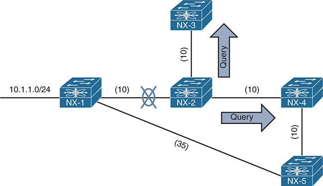
Figure 7-13 EIGRP Convergence Topology
The following steps are processed in order from the perspective of NX-2 calculating a new route to the 10.1.1.0/24 network.
Step 1. NX-2 detects the link failure. NX-2 did not have a feasible successor for the route, set the 10.1.1.0/24 prefix as active, and sent Queries to NX-3 and NX-4.
Step 2. NX-3 receives the Query from NX-2, and processes the delay field that is set to infinity. NX-3 does not have any other EIGRP neighbors and sends a Reply to NX-2 that a route does not exists. NX-4 receives the Query from NX-2 and processes the delay field that is set to infinity. Because the Query was received by the successor, and a feasible successor for the prefix does not exist, NX-4 marks the route as active and sends a Query to NX-5.
Step 3. NX-5 receives the Query from NX-4 and detects that the delay field is set to infinity. Because the Query was received by a nonsuccessor, and a successor exists on a different interface, a REPLY for the 10.4.4.0/24 network is sent back to NX-4 with the appropriate EIGRP attributes.
Step 4. NX-4 receives NX-5’s Reply, acknowledges the packet, and computes a new path. Because this is the last outstanding Query packet on NX-4, NX-4 sets the prefix as passive. With all Queries satisfied, NX-4 responds to NX-2’s query with the new EIGRP metrics.
Step 5. NX-2 receives NX-4’s Reply, acknowledges the packet, and computes a new path. Because this is the last outstanding Query packet on NX-4, NX-4 sets the prefix as passive.
Stuck in Active
DUAL is very efficient at finding loop-free paths quickly, and normally finds a backup path in seconds. Occasionally an EIGRP Query is delayed because of packet loss, slow neighbors, or a large hop count. EIGRP waits half of the active timer (90 seconds default) for a Reply. If the router does not receive a response within 90 seconds, the originating router sends a Stuck In Active (SIA) Query to EIGRP neighbors that have not responded.
Upon receipt of a SIA-Query, the router should respond within 90 seconds with a SIA-REPLY. A SIA-Reply contains the route information, or provides information on the Query process itself. If a router fails to respond to a SIA-Query by the time the active timer expires, EIGRP deems the router as Stuck In Active (SIA). If the SIA state is declared for a neighbor, DUAL deletes all routes from that neighbor and treats the situation as if the neighbor responded with unreachable messages for all routes. Active Queries are shown with the command show ip eigrp topology active.
Figure 7-14 shows a topology where the link between NX-1 and NX-2 has failed. NX-2 sends out Queries to NX-4 and NX-3 for the 10.1.1.0/24 and 10.12.1.0/24 networks. NX-4 sends a Reply back to NX-2, and NX-3 sends a Query onto R5, which then sends a query on to R6.

Figure 7-14 EIGRP SIA Topology
A network engineer sees the syslog message for the down link and immediately runs the show ip eigrp topology active command on NX-2 and sees output the output from Example 7-54.
The “r” next to the 10.23.1.3 indicates that NX-2 is still waiting on the reply from NX-3. NX-1 is registered as down, and the path is set to infinity. The show ip eigrp topology command can then be executed on NX-3, which indicates it is waiting on a response from NX-5. Then the command can be run again on R5, which indicates it is waiting on R6. Executing the command on R6 does not show any active prefixes, inferring that R6 never received a Query from R5. R5’s Query could have been dropped on the wireless connection.
Example 7-54 Output for SIA Timers
IP-EIGRP Topology Table for AS(100)/ID(10.23.1.2) VRF default
Codes: P - Passive, A - Active, U - Update, Q - Query, R - Reply,
r - reply Status, s - sia Status
A 10.1.1.0/24, 0 successors, FD is 768
1 replies, active 00:00:08, query-origin: Local origin
via 10.12.1.1 (Infinity/Infinity), Ethernet1/2
Remaining replies:
1 replies, active 00:00:08, query-origin: Local origin
via Connected (Infinity/Infinity), Ethernet1/2
Remaining replies:
via 10.23.1.3, r, Ethernet1/1
After the 90-second window has passed, the switch sends out a SIQ Query, which is seen by examining the EIGRP traffic counters. Example 7-55 displays the traffic counters before and after the 90-second window.
Example 7-55 EIGRP Traffic Counters with SIA Queries and Replies
NX-2# show ip eigrp traffic
IP-EIGRP Traffic Statistics for AS 100 VRF default
Hellos sent/received: 65/64
Updates sent/received: 0/0
Queries sent/received: 2/0
Replies sent/received: 0/1
Acks sent/received: 1/2
Input queue high water mark 3, 0 drops
SIA-Queries sent/received: 0/0
SIA-Replies sent/received: 0/0
Hello Process ID: (no process)
PDM Process ID: (no process)
NX-2# show ip eigrp traffic
IP-EIGRP Traffic Statistics for AS 100 VRF default
Hellos sent/received: 115/115
Updates sent/received: 7/6
Queries sent/received: 2/0
Replies sent/received: 0/1
Acks sent/received: 7/9
Input queue high water mark 3, 0 drops
SIA-Queries sent/received: 2/0
SIA-Replies sent/received: 0/2
Hello Process ID: (no process)
PDM Process ID: (no process)
Example 7-56 displays the EIGRP topology table after the SIA Replies are received. And just after that, the SIA message appears in the syslog, and the EIGRP peering is reset.
Example 7-56 Topology Table After SIA Replies
IP-EIGRP Topology Table for AS(100)/ID(10.23.1.2) VRF default
Codes: P - Passive, A - Active, U - Update, Q - Query, R - Reply,
r - reply Status, s - sia Status
A 10.1.1.0/24, 0 successors, FD is 768
1 replies, active 00:04:40, query-origin: Local origin, retries(3)
via 10.12.1.1 (Infinity/Infinity), Ethernet1/2
via 10.23.1.3 (Infinity/Infinity), r, Ethernet1/1, serno 112
A 10.12.1. 0/24, 1 successors, FD is Inaccessible
1 replies, active 00:04:40, query-origin: Local origin, retries(3)
via Connected (Infinity/Infinity), Ethernet1/2
via 10.23.1.3 (Infinity/Infinity), r, Ethernet1/1, serno 111
03:57:41 NX-2 %EIGRP-3-SIA_DUAL: eigrp-NXOS [8394] (default-base) Route 10.12.1.0/24 stuck-in-active state in IP-EIGRP(0) 100. Cleaning up
03:57:41 NX-2 %EIGRP-5-NBRCHANGE_DUAL: eigrp-NXOS [8394] (default-base) IP-EIGRP(0) 100: Neighbor 10.23.1.3 (Ethernet1/1) is down: stuck in active
03:57:42 NX-2 %EIGRP-5-NBRCHANGE_DUAL: eigrp-NXOS [8394] (default-base) IP-EIGRP(0) 100: Neighbor 10.23.1.3 (Ethernet1/1) is up: new adjacency
Having an invalid route stuck in the routing table because of a busy router can be frustrating. There are two possible solutions:
Change the active timer to a different value with the command timers active-time {disabled | 1-65535_minutes} under the EIGRP process.
Use network summarization within the network design. EIGRP summarization is useful for creating query boundaries to reduce the realm that a query will be executed in.
The active timer is shown by examining the EIGRP process with the show ip eigrp command. The SIA timer is displayed in the Active Timer field. Example 7-57 displays the active timer value of three minutes.
Example 7-57 Output for SIA Timers
..
Max paths: 8
Summary
This chapter provided a logical overview of how the most common issues with EIGRP can be identified so that any issue can be remediated.
The following parameters must match when troubleshooting EIGRP adjacency with other devices:
Interfaces must be Active.
Connectivity between devices must exist using the primary subnet.
Autonomous system number (ASN) matches.
Metric formula K values.
Authentication parameters.
EIGRP is a distance vector routing protocol, which creates a topology map based on the information it has received from downstream neighbors. When troubleshooting suboptimal path selection or missing routes, it is best to start at the destination and work toward the source of the route. Along each hop, the following items should be checked to see if there is explicit modification of path information:
EIGRP adjacency with another device that is toward the source.
Enablement of the EIGRP stub feature.
Filtering by hop-count or distribute-list.
Manipulation of metrics. This can be an offset list to increase the metric for that path, or the explicit configuration of bandwidth or delay for an interface.
A router that is using two different processes to contain the upstream and downstream routing interface. In these instances the routes need to be mutually redistributed between the processes.
Poorly planned implementation of EIGRP wide metrics that does not take into account the scale factor on higher speed interfaces.
EIGRP’s DUAL algorithm is extremely intelligent and overcomes barriers that apply to most vector-based routing protocols. DUAL provides fast convergence, but occasionally has difficulties during convergence when remote routers become unresponsive. The convergence time period can be reduced by implementing lower SIA timers, or through the deployment of route summarization.
References
RFC 7868, Cisco’s Enhanced Interior Gateway Routing Protocol (EIGRP). Savage, D., J. Ng, S. Moore, et al. IETF, https://tools.ietf.org/html/rfc7868, May 2016.
Edgeworth, Brad, Aaron Foss, and Ramiro Garza Rios. IP Routing on Cisco IOS, IOS XE and IOS XR. Indianapolis: Cisco Press, 2014.
Cisco. Cisco NX-OS Software Configuration Guides, http://www.cisco.com.