Chapter 9
Troubleshooting Intermediate System-Intermediate System (IS-IS)
This chapter covers the following topics:
Intermediate System-to-Intermediate System (IS-IS) is a link-state routing protocol that is commonly found in service providers and some enterprise networks. IS-IS provides fast convergence, supports a large number of networks, and can support multiple protocols. Cisco uses IS-IS in a lot of underlying technologies, such as Overlay Transport Virtualization (OTV), Application Centric Infrastructure (ACI), and Software Defined Access (SD-Access).
This chapter focuses on identifying and troubleshooting issues that are caused with forming IS-IS neighbor adjacency, path selection, missing routes, and problems with convergence.
IS-IS Fundamentals
IS-IS uses a two-level hierarchy consisting of Level 1 (L1) and Level 2 (L2) connections. IS-IS communication occurs at L1, L2, or both (L1-L2). L2 routers communicate only with other L2 routers, and L1 routers communicate only with other L1 routers. L1-L2 routers provide connectivity between the L1 and L2 levels. An L2 router can communicate with L2 routers in the same or a different area, whereas an L1 router communicates only with other L1 routers within the same area. The following list indicates the type of adjacencies that are formed between IS-IS routers:
L1 ← → L1
L2 ← → L2
L1-L2 ← → L1
L1-L2 ← → L2
L1-L2 ← → L1-L2
Note
The terms L1 and L2 are used frequently in this chapter, and refer only to the IS-IS levels. They should not be confused with the OSI model.
IS-IS uses the link-state packets (LSP) for building a link-state packet database (LSPDB) similar to OSPF’s link-state database (LSDB). IS-IS then runs the Dijkstra Shortest Path First (SPF) algorithm to construct a loop-free topology of shortest paths.
Areas
OSPF and IS-IS use a two-level hierarchy but work differently between the protocols. OSPF provides connectivity between areas by allowing a router to participate in multiple areas, whereas IS-IS places the entire router and all its interfaces in a specific area. OSPF’s hierarchy is based on areas advertising prefixes into the backbone, which then are advertised into nonbackbone areas. Level 2 is the IS-IS backbone and can cross multiple areas, unlike OSPF, as long as the L2 adjacencies are contiguous.
Figure 9-1 demonstrates these basic differences between OSPF and IS-IS. Notice that the IS-IS backbone extends across four areas, unlike OSPF’s backbone, which is limited to Area 0.

Figure 9-1 Comparison of Areas Between OSPF and IS-IS
In Figure 9-2, NX-1 and NX-2 form an L1 adjacency with each other, and NX-4 and NX-5 form an L1 adjacency with each other. Although NX-2 and NX-4 are L1-L2 routers, NX-1 and NX-5 support only an L1 connection. The area address must be the same to establish an L1 adjacency. NX-2 establishes an L2 adjacency with NX-3, and NX-3 establishes an L2 adjacency with NX-4. NX-2 and NX-4 are L1-L2 routers and can form an L1 and L2 adjacency on them.

Figure 9-2 IS-IS Adjacencies
All L1 IS-IS routers in the same level maintain an identical copy of the LSPDB, and all L1 routers do not know about any routers or networks outside of their level (area). In a similar fashion, L2 routers maintain a separate LSPDB that is identical with other L2 routers. L2 routers are aware only of other L2 routers and networks in the L2 LSPDB.
L1-L2 routers inject L1 prefixes into the L2 topology. L1-L2 routers do not advertise L2 routes into the L1 area, but they set the attached bit in their L1 LSP, indicating that the router has connectivity to the IS-IS backbone network. If an L1 router does not have a route for a network, it searches the LSPDB for the closest router with the attached bit, which acts as a route of last resort.
NET Addressing
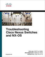
IS-IS routers share an area topology through link-state packets (LSP) that allows them to build the LSPDB. IS-IS uses NET addresses to build the LSPDB topology. The NET address is included in the IS header for all the LSPs. Ensuring that a router is unique in an IS-IS routing domain is essential for properly building the LSPDB. NET addressing is based off the OSI model’s Network Service Access Point (NSAP) address structure that is between 8 to 20 bytes in length. NSAP addressing is variable based on the logic for addressing domains.
The dynamic length in the Inter-Domain Part (IDP) portion of the NET address causes unnecessary confusion. Instead of reading the NET address left to right, most network engineers read the NET address from right to left. In the most simplistic form, the first byte is always the selector (SEL) (with a value of 00), with the next 6 bytes as the system ID, and the remaining 1 to 13 bytes are the Area Address, as shown in Figure 9-3.

Figure 9-3 Expanded NSAP Address Structure
Figure 9-4 demonstrates three variations of NET addressing:
A simple 8-byte NET address structure. The Authority and Format Identifier (AFI) is not needed because the length does not enter into the Inter-Domain Part (IDP) portion of the NSAP address. Notice that the Area Address is 1-byte, which provides up to 256 unique areas.
A common 10-byte NET address structure. The private AFI (49) is used, and the area uses 2 bytes, providing up to 65,535 unique areas. Notice that the Area Address is 49.1234.
Typical Open System Interconnection (OSI) NSAP address that includes the domain address. Notice that the Area Address is 49.0456.1234 and that the private AFI (49) is used.
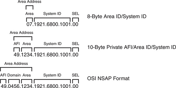
Figure 9-4 Example NET Address Structures
Note
In essence, the router’s System ID is equivalent to EIGRP, or OSPF’s router-id. The NET address is used to construct the network topology and must be unique.
Inter-Router Communication
Unlike other routing protocols, intermediate system (IS) communication is protocol independent because inter-router communication is not encapsulated in the third layer (network) of the OSI model. IS communication uses the second layer of the OSI model. IP, IPv6, and other protocols all use the third layer addressing in the OSI model.
IS protocol data units (PDU) (packets) follow a common header structure that identifies the type of the PDU. Data specific to each PDU type follows the header, and the last fields use optional variable-length fields that contain information specific to the IS PDU type.
IS packets are categorized into three PDU types, with each type differentiating between L1 and L2 routing information:
IS-IS Hello (IIH) Packets: IIH packets are responsible for discovering and maintaining neighbors.
Link State Packets (LSP): LSPs provide information about a router and associated networks. Similar to an OSPF LSA, except OSPF uses multiple LSAs.
Sequence Number Packets (SNP): Sequence number packets (SNP) control the synchronization process of LSPs between routers.
Complete sequence number packets (CSNP) provide the LSP headers for the LSPDB of the advertising router to ensure the LSPDB is synchronized.
Partial sequence number packets (PSNP) acknowledge receipt of a LSP on point-to-point networks and request missing link state information when the LSPDB is identified as being out of sync.
IS Protocol Header
Every IS packet includes a common header that describes the PDU. All eight fields are 1-byte long and are in all packets.
Table 9-1 provides an explanation for the fields listed in the IS Protocol Header.
Field |
Description |
Intra Domain Routing Protocol Discriminator (Protocol Identifier) |
Network Layer identifier assigned by ISO. IS-IS communication uses 0×83. ES-IS communication uses 0×81. |
PDU Header Length |
Length of PDU Header because it is dynamic in nature. |
Version |
Protocol Version Identifier. |
System ID Length |
The system ID can be between 1–8 bytes; network vendors have standardized on 6 bytes. This field indicates the length of the system ID. A value of 0 infers the default length of 6 bytes. |
PDU Type |
1-byte representation of the PDU type. Indicates whether it is a Hello, LSP, or SNP. |
Reserved |
Indicates the level of the packet. A value of 1 indicates Level 1 only; 2 indicates L2 with manual mode. |
Max Areas |
Value between 1 and 254 to represent the number of areas that a router will support. Default value is 3. |
ISO 10589 states that a value of 0 in the IS packet header is treated in a special way in for the IS Type, LSPF Database Overload Bit, and Maximum Area Addresses field. A value of zero infers the default setting indicated in Table 9-1.
TLVs
A portion of IS PDUs uses variable modules that contain routing information. Each module specifies the type of information, length of data, and the value itself, and are commonly referred to as type, length, and value (TLV) tuples. Every TLV maintains a 1-byte numeric label to identify the type (function) and length of the data. TLVs support the capability of nesting, so a sub-TLV can exist inside another TLV.
TLVs provide functionality and scalability to the IS protocol. Developing new features for the IS protocol involves the addition of TLVs to the existing structure. For example, IPv6 support was added to the IS protocol by adding TLV #232 (IPv6 Interface Address) and #236 (IPv6 Reachability).
IS PDU Addressing
Communication between IS devices uses Layer 2 addresses. The source address is always the network interface’s Layer 2 address, and the destination address varies depending upon the network type. Nexus switches are Ethernet based and therefore use Layer 2 MAC addresses for IS-IS communication.
ISO standards classify network media into two categories: broadcast and general topology.
Broadcast networks provide communication to multiple devices with a single packet. Broadcast interfaces communicate in a multicast fashion using well-known Layer 2 addresses so that only the nodes running IS-IS process the traffic. IS-IS does not send unicast traffic on broadcast network types, because all routers on the segment should be aware of what is happening with the network.
Table 9-2 provides a list of destination MAC addresses used for IS communication.
Table 9-2 IS-IS Destination MAC Addresses
Name |
Destination MAC Address |
All L1 ISs |
0180.c200.0014 |
All L2 ISs |
0180.c200.0015 |
All Intermediate Systems |
0900.2b00.0005 |
All End Systems |
0900.2b00.0004 |
General topology networks are based off network media that allows communication only with another device if a single packet is sent out. General topology networks are often referred to in IS-IS documentation as point-to-point networks. Point-to-point networks communicate with a directed destination address that matches the Layer 2 address for the remote device. NBMA technologies such as Frame Relay may not guarantee communication to all devices with a single packet. A common best practice is to use point-to-point subinterfaces on NMBA technologies to ensure proper communication between IS-IS nodes.
IS-IS Hello (IIH) Packets
IS-IS Hello (IIH) packets are responsible for discovering and maintaining neighbors. IS-IS communication has five types of hellos listed in Table 9-3. Only the first three are involved with IS-IS neighbor adjacencies; the other two are related to ES-IS communication.
Routers that form an L1-L2 adjacency with another IS-IS router send both L1 and L2 IIHs on broadcast links. To save bandwidth on WAN links, point-to-point links use the Point-to-Point Hello, which services both L1 and L2 adjacencies.
Table 9-3 provides a brief overview of the five IS Hello packet types.
Type |
Description |
L1 IS-IS Hello (IIH) PDU Type 15 |
Discovers, forms, and maintains Level 1 IS-IS neighbors |
L2 IS-IS Hello (IIH) PDU Type 16 |
Discovers, forms, and maintains Level 2 IS-IS neighbors |
Point-to-Point Hello (IIH) IS-IS PDU Type 17 |
Discovers, forms, and maintains point-to-point IS-IS neighbors |
End System Hello (ESH) |
Used for end systems (ES) to discover intermediate systems (IS) and vice versa; similar to ICMP |
Intermediate System Hello (ISH) |
Used for end systems (ES) to discover intermediate systems (IS) and vice versa for router selection |
Table 9-4 provides a brief list of information included in the IIH Hello Packet.
Table 9-4 Fields in IIH Packets
Type |
Description |
Circuit Type |
0×1 Level 1 only 0×2 Level 2 only 0×3 Level 1 and Level 2 |
System-ID |
System ID of router sending the IIH |
Holding Timer |
Holding Timer to be used for this Intermediate System |
PDU Length |
Entire Length of the PDU |
Priority |
Router interface priority for Designated Intermediate System (DIS) elections (This is not included on point-to-point IIHs.) |
System-ID of DIS |
System ID of DIS for the Broadcast Segment (This is not included on point-to-point IIHs.) |
Table 9-5 provides a list of common TLVs found in IIH PDUs.
Table 9-5 Common TLVs Found in IIH PDUs
TLV Number |
Name |
Description |
|
1 |
Area Addresses |
List of Area Addresses from advertising router. |
|
6 |
IS Neighbors |
List of subnetwork point of addresses (SNPA) from a neighboring IS router. SNPA is the Layer 2 hardware addresses for IS-IS routers. (Not included on point-to-point hellos) |
|
8 |
Padding |
TLVs used to inflate the packet to full maximum transmission unit (MTU). Data within this TLV is ignored. |
|
10 |
Authentication |
Identifies the type of authentication and includes the plain-text password or the MD5 hash. |
|
132 |
IP Interface Addresses |
List of IP Addresses from the transmitting interface that includes secondary IP addresses. |
|
240 |
Adjacency State |
Used by point-to-point links to ensure three-way IS-IS handshakes. |
|
Link-State Packets
Link-state packets (LSP) are similar to OSPF LSAs where they advertise neighbors and attached networks, except that IS-IS uses only two types of LSPs. IS-IS defines a LSP type for each level. L1 LSPs are flooded throughout the area they originate, and L2 LSPs are flooded throughout the Level 2 network.
LSP ID
The LSP ID is a fixed 8-byte field that provides a unique identification of the LSP originator. The LSP ID is composed of the following:
System ID (6 bytes): The system ID is extracted from the NET address configured on the router.
Pseudonode ID (1 byte): The pseudonode ID identifies the LSP for a specific pseudonode (virtual router) or for the physical router. LSPs with a pseudonode ID of zero describe the links from the system and can be called non-pseudonode LSPs.
LSPs with a nonzero number indicate that the LSP is a pseudonode LSP. The pseudonode ID correlates to the router’s circuit ID for the interface performing the designated intermediate system (DIS) function. The pseudonode ID is unique among any other broadcast segments for which the same router is the DIS on that level. Pseudonodes and DIS are explained later in this chapter.
Fragment ID (1 byte): If an LSP is larger than the max MTU value of the interface it needs to be sent out of, that LSP must be fragmented. IS-IS fragments the LSP as it is created, and the fragment-ID allows the receiving router to process fragmented LSPs.
Figure 9-5 shows two LSP IDs. The LSP ID on the left indicates that it is for a specific IS router, and the LSP ID on the right indicates that it is for the DIS because the pseudonode ID is not zero.

Figure 9-5 LSP ID Structure
Attribute Fields
The last portion of the LSP header is an 8-bit section that references four components of the IS-IS specification:
Partition Bit: The partition bit identifies whether a router supports the capability for partition repair. Partition repair allows a broken L1 area to be repaired by L2 routers that belong to the same area as the L1 routers. Cisco and most other network vendors do not support partition repair.
Attached Bit: The next four bits reflect the attached bit set by a L1-L2 router connected to other areas via the L2 backbone. The attached bit is in L1 LSPs.
Overload Bit: The overload bit indicates when a router is in an overloaded condition. During SPF calculation, routers should avoid sending traffic through this router. Upon recovery, the router advertises a new LSP without the overload bit, and the SPF calculation occurs normally without avoiding routes through the previously overloaded node.
Router Type: The last two bits indicate whether the LSP is from a L1 or L2 router.
LSP Packet and TLVs
Table 9-6 provides a list of common TLVs found in LSPs, which are used to build the topology table and for placing routes into the routing information base (RIB).
Table 9-6 Common TLVs Found in LSP PDUs
TLV Number |
Name |
Description |
1 |
Area Addresses |
List of Area Addresses on the configured router. |
2 |
IS Neighbors |
List of subnetwork point of addresses (SNPA) from a neighboring IS router and associated interface metric. SNPA is the Layer 2 hardware addresses for IS-IS routers. |
10 |
Authentication |
Identifies the type of authentication and includes the plain-text password or the MD5 hash. |
128 |
IP Internal Reachability Information |
List of internal IS-IS network and interface metric for the advertising router. |
130 |
IP External Reachability Information |
List of external (redistributed) networks and metrics associated when redistributed into IS-IS. Metrics can be internal or external. |
132 |
IP Interface Addresses |
List of IP addresses from the transmitting interface, which includes secondary IP addresses. (Limited to 63 IP addresses within the TLV.) |
137 |
Hostname |
Router hostname so that it can be used to identify the router in lieu of the system ID. |
Designated Intermediate System
Broadcast networks allow more than two routers to exist on a network segment. This could cause scalability problems with IS-IS as the number of routers on a segment increase. Additional routers flood more LSPs on the segment, and ensuring that the databases are synchronized can be resource intensive.
IS-IS overcomes this inefficiency by creating a pseudonode (virtual router) to manage the synchronization issues that arise on the broadcast network segment. A router on the broadcast segment, known as the Designated Intermediate System (DIS), assumes the role of the pseudonode. If the acting DIS router fails, another router becomes the new DIS and assumes the responsibilities. A pseudonode and DIS exist for each IS-IS level (L1 and L2) which means that a broadcast segment can have two pseudonodes and two DISs.
By inserting the logical pseudonode into a broadcast segment, the multi-access network segment is converted into multiple point-to-point networks in the LSPDB.
Note
There is a natural tendency to associate IS-IS DIS behavior with OSPF’s designated router (DR) behavior, but they operate in a different nature. All IS-IS routers form a full neighbor adjacency with each other. Any router can advertise non-pseudonode LSPs to all other IS-IS routers on that segment, whereas OSPF specifies that LSAs are sent to the DR to be advertised to the network segment.
The DIS advertises a pseudonode LSP that indicates the routers that attach to the pseudonode. The pseudonode LSP acts like an OSPF Type-2 LSA because it indicates the attached neighbors and informs the nodes which router is acting as the DIS. The system IDs of the routers connected to the pseudonode are listed in the IS Reachability TLV with an interface metric set to zero because SPF uses the metric for the non-pseudonode LSPs for calculating the SPF tree.
The pseudonode advertises the complete sequence number packets (CSNP) every 10 seconds. IS-IS routers check their LSPDBs to verify that all LSPs listed in the CSNP exist, and that the sequence number matches the version in the CSNP.
If an LSP is missing or the router has an outdated (lower sequence number) LSP than what is contained in the CSNP, the router advertises a partial sequence number packet (PSNP) requesting the correct or missing LSP. All IS-IS routers receive the PSNP, but only the DIS sends out the correct LSP, thereby reducing traffic on that network segment.
If a router detects that the sequence number in the CSNP is lower than the sequence number for any LSP that is stored locally in its LSPDB, it advertises the local LSP with the higher sequence number. All IS-IS routers receive the LSP and process it accordingly. The DIS should send out an updated CSNP with the updated sequence number for the advertised LSP.
Path Selection
Note that the IS-IS path selection is quite straightforward after reviewing the following key definitions:
Intra-area routes are routes that are learned from another router within the same level and area address.
Inter-area routes are routes that are learned from another L2 router that came from a L1 router or from a L2 router from a different area address.
External routes are routes that are redistributed into the IS-IS domain. External routes can choose between two metric types:
Internal metrics are directly comparable with IS-IS path metrics and are selected by default by Nexus switches. IS-IS treats these routes with the same preferences as those advertised normally via TLV #128.
External metrics cannot be comparable with internal path metrics.
IS-IS best-path selection follows the processing order shown in the following steps to identify the route with the lowest path metric for each stage.
Step 1. L1 intra-area routes
L1 external routes with internal metrics
Step 2. L2 intra-area routes
L2 external routes with internal metric
L1→L2 inter-area routes
L1→L2 inter-area external routes with internal metrics
Step 3. Leaked routes (L2→L1) with internal metrics
Step 4. L1 external routes with external metrics
Step 5. L2 external routes with external metrics
L1→L2 inter-area external routes with external metrics
Step 6. Leaked routes (L2→L1) with external metrics
Note
Under normal IS-IS configuration, only the first three steps are used. External routes with external metrics require the external metric-type to be explicitly specified in the route-map at the time of redistribution.
Troubleshooting IS-IS Neighbor Adjacency
Now that an overview of the IS-IS protocol has been provided, let’s review the IS-IS configuration for NX-OS and begin troubleshooting neighbor adjacency issues.
Baseline IS-IS Configuration
The IS-IS configuration process on a NX-OS switch requires configuration under the IS-IS process and under the interface configuration submode. The following steps explain the process for configuring IS-IS on a Nexus switch.
Step 1. Enable the IS-IS feature. The IS-IS feature must be enabled with the global configuration command feature isis.
Step 2. Define an IS-IS process tag. The IS-IS process must be defined with the global configuration command router isis instance-tag. The instance-tag can be up to 20 alphanumeric characters in length.
Step 3. Define the IS-IS NET address. The NET address must be configured with the command net net-address.
Step 4. Define the IS-IS type (optional). By default, Nexus switches operate at L1-L2 IS-IS types. This means that an L1 adjacency is formed with L1 neighbors, a L2 adjacency is formed with L2 neighbors, and two sessions (L1 and L2) are formed with another L1-L2 IS-IS peer.
The IS-IS router type is changed with the command is-type {level-1 | level- 1-2 | level-2}.
Step 5. Enable L1 route propagation to L2 networks (optional). Nexus switches do not propagate L1 networks to L2 networks automatically. The command distribute level-1 into level-2 {all | route-map route-map-name}.
Step 6. Enable IS-IS on interfaces. The interface that IS-IS is enabled on is selected with the command interface interface-id. The IS-IS process is then enabled on that interface with the command ip router isis instance-tag.
The configuration in Example 9-1 enables IS-IS only on interfaces Ethernet1/1, VLAN 10, and Loopback 0.
Example 9-1 Baseline IS-IS Configuration
Enter configuration commands, one per line. End with CNTL/Z.
NX-1(config)# feature isis
NX-1(config)# router isis NXOS
13:27:13 NX-1 isis[11140]: ISIS-6-START: Process start. Reason – configuration
NX-1(config-router)# net 49.0012.0000.0000.0001.00
NX-1(config-router)# interface lo0
NX-1(config-if)# ip router isis NXOS
NX-1(config-if)# interface ethernet1/1
NX-1(config-if)# ip router isis NXOS
NX-1(config-if)# interface VLAN10
NX-1(config-if)# ip router isis NXOS
Enter configuration commands, one per line. End with CNTL/Z.
NX-2(config)# feature isis
NX-2(config)# router isis NXOS
13:32:22 NX-1 isis[11140]: ISIS-6-START: Process start. Reason – configuration
NX-2(config-router)# net 49.0012.0000.0000.0002.00
NX-2(config-router)# interface lo0
NX-2(config-if)# ip router isis NXOS
NX-2(config-if)# interface ethernet1/1
NX-2(config-if)# ip router isis NXOS
NX-2(config-if)# interface VLAN20
NX-2(config-if)# ip router isis NXOS
13:33:11 NX-2 %ISIS-5-ADJCHANGE: isis-NXOS [24168] LAN adj L2 0000.0000.0001
over Ethernet1/1 - INIT (New) on MT--1
13:33:11 NX-2 %ISIS-5-ADJCHANGE: isis-NXOS [24168] LAN adj L2 0000.0000.0001
over Ethernet1/1 - UP on MT-0
13:33:11 NX-2 %ISIS-5-ADJCHANGE: isis-NXOS [24168] LAN adj L1 0000.0000.0001
over Ethernet1/1 - INIT (New) on MT--1
13:33:11 NX-2 %ISIS-5-ADJCHANGE: isis-NXOS [24168] LAN adj L1 0000.0000.0001
over Ethernet1/1 - UP on MT-0
IS-IS requires that neighboring routers form an adjacency before LSPs are processed. The IS-IS neighbor adjacency process consists of three states: down, initializing, and up. This section explains the process for troubleshooting IS-IS neighbor adjacencies on Nexus switches.
Figure 9-6 provides a simple topology with two Nexus switches that are used to explain how to troubleshoot IS-IS adjacency problems.

Figure 9-6 Simple Topology with Two NX-OS Switches
IS-IS Neighbor Verification
The first step is to verify devices that have successfully established an IS-IS adjacency with the command show isis adjacency [interface interface-id] [detail | summary] [vrf {vrf-name]. The detail keyword parameter provides the neighbor’s uptime and any secondary IP addresses configured on the neighboring nodes.
Example 9-2 displays the output of the nondetailed command on NX-1. Notice that there is an entry for the L1 adjacency and a separate entry for the L2 adjacency. This is expected behavior for L1-L2 adjacencies with other routers.
Example 9-2 Display of IS-IS Neighbors
IS-IS process: NXOS VRF: default
IS-IS adjacency database:
Legend: '!': No AF level connectivity in given topology
System ID SNPA Level State Hold Time Interface
NX-2 0021.21ae.c123 1 UP 00:00:07 Ethernet1/1
NX-2 0021.21ae.c123 2 UP 00:00:07 Ethernet1/1
Table 9-7 provides a brief overview of the fields used in Example 9-2. Notice that the Holdtime for NX-2 is relatively low because NX-2 is the DIS for the 10.12.1.0/24 network.
Table 9-7 IS-IS Neighbor State Fields
Field |
Description |
System ID |
The system ID (SEL) abstracted from the NET address. |
Subnetwork Point of Addresses (SNPA) |
Layer 2 hardware addresses for IS-IS routers. Nexus switches will always show the MAC address because of Ethernet. |
Level |
Type of adjacency formed with a neighbor: L1, L2, or L1-L2. |
State |
Displays whether the neighbor is up or down. |
Holdtime |
Time required to receive another IIH to maintain the IS-IS adjacency. |
Interface |
Interface used to peer with neighbor router. |
Note
Notice that the system ID actually references the router’s hostname instead of the 6-byte system ID. IS-IS provides a name to system ID mapping under the optional TLV #137 that is found as part of the LSP. This feature is disabled under the IS-IS router configuration with the command no hostname dynamic.
Example 9-3 displays the show isis adjacency command using the summary and detail keywords. Notice that the optional detail keyword provides accurate timers for transition states for a particular neighbor.
Example 9-3 Display of IS-IS Neighbors with summary and detail Keywords
IS-IS process: NXOS VRF: default
IS-IS adjacency database summary:
Legend: '!': No AF level connectivity in given topology
P2P UP INIT DOWN All
L1 0 0 0 0
L2 0 0 0 0
L1-2 0 0 0 0
SubTotal 0 0 0 0
LAN UP INIT DOWN All
L1 1 0 0 1
L2 1 0 0 1
SubTotal 2 0 0 2
Total 2 0 0 2
IS-IS process: NXOS VRF: default
IS-IS adjacency database:
Legend: '!': No AF level connectivity in given topology
System ID SNPA Level State Hold Time Interface
NX-2 0021.21ae.c123 1 UP 00:00:06 Ethernet1/1
Up/Down transitions: 1, Last transition: 00:38:30 ago
Circuit Type: L1-2
IPv4 Address: 10.12.1.200
IPv6 Address: 0::
Circuit ID: NX-2.01, Priority: 64
BFD session for IPv4 not requested
BFD session for IPv6 not requested
Restart capable: 1; ack 0;
Restart mode: 0; seen(ra 0; csnp(0; l1 0; l2 0)); suppress 0
NX-2 0021.21ae.c123 2 UP 00:00:08 Ethernet1/1
Up/Down transitions: 1, Last transition: 00:38:30 ago
Circuit Type: L1-2
IPv4 Address: 10.12.1.200
IPv6 Address: 0::
Circuit ID: NX-2.01, Priority: 64
BFD session for IPv4 not requested
BFD session for IPv6 not requested
Restart capable: 1; ack 0;
Restart mode: 0; seen(ra 0; csnp(0; l1 0; l2 0)); suppress 0
Besides enabling IS-IS on the network interfaces on Nexus switches, the following parameters must match for the two switches to become neighbors:
IS-IS interfaces must be Active.
Connectivity between devices must exist using the primary subnet.
MTU matches.
L1 adjacencies require the area address to match the peering L1 router, and the system ID must be unique between neighbors.
L1 routers can form adjacencies with L1 or L1-L2 routers, but not L2.
L2 routers can form adjacencies with L2 or L1-L2 routers, but not L1.
DIS requirements match.
IIH Authentication Type & Credentials (if any).
Confirmation of IS-IS Interfaces
If a neighbor adjacency is missing for a specific IS-IS level, it is important to verify that the correct interfaces are running IS-IS for that level. The command show isis interface [interface-id | brief ] [level-1 | level-2] [vrf vrf-name] lists all the interfaces and any relevant information for IS-IS enabled interfaces. Providing a specific interface limits the output to the specified interface.
Some of the output in Example 9-4 has been omitted for brevity, but the following relevant information is shown in the output:
The IS-IS interface is operating as a L1-L2 interface (Cisco default).
The Default MTU is 1500 for Ethernet.
The LAN ID (pseudonode ID) is NX-1.01.
L1 and L2 metrics are set to 10 (Cisco default).
Two IS-IS adjacencies have formed at the L1 and L2 level.
The priority for the interface is 64 for L1 and L2 (Cisco default).
Example 9-4 IS-IS Interface Verification
Ethernet1/1, Interface status: protocol-up/link-up/admin-up
IP address: 10.12.1.100, IP subnet: 10.12.1.0/24
IPv6 routing is disabled
Auth check set
Auth check set
Index: 0x0002, Local Circuit ID: 0x01, Circuit Type: L1-2
BFD IPv4 is locally disabled for Interface Ethernet1/1
BFD IPv6 is locally disabled for Interface Ethernet1/1
MTR is disabled
LSP interval: 33 ms, MTU: 1500
Level Metric-0 Metric-2 CSNP Next CSNP Hello Multi Next IIH
1 4 0 10 00:00:07 10 3 00:00:04
2 4 0 10 00:00:08 10 3 0.384739
Level Adjs AdjsUp Pri Circuit ID Since
1 1 0 64 NX-1.01 00:57:39
2 1 0 64 NX-1.01 00:57:39
Topologies enabled:
L MT Metric MetricCfg Fwdng IPV4-MT IPV4Cfg IPV6-MT IPV6Cfg
1 0 4 no UP UP yes DN no
2 0 4 no UP UP yes DN no Metric (L1/L2): 10/10
loopback0, Interface status: protocol-up/link-up/admin-up
IP address: 192.168.100.100, IP subnet: 192.168.100.100/32
IPv6 routing is disabled
Level1
No auth type and keychain
Auth check set
Level2
No auth type and keychain
Auth check set
Index: 0x0001, Local Circuit ID: 0x01, Circuit Type: L1-2
BFD IPv4 is locally disabled for Interface loopback0
BFD IPv6 is locally disabled for Interface loopback0
MTR is disabled
Level Metric
1 1
2 1
Topologies enabled:
L MT Metric MetricCfg Fwdng IPV4-MT IPV4Cfg IPV6-MT IPV6Cfg
1 0 1 no UP UP yes DN no
2 0 1 no UP UP yes DN no
IS-IS process: NXOS VRF: default
Interface Type Idx State Circuit MTU Metric Priority Adjs/AdjsUp
L1 L2 L1 L2 L1 L2
--------------------------------------------------------------------------------
Topology: TopoID: 0
Vlan10 Bcast 3 Down/Ready 0x02/L1-2 1500 4 4 64 64 0/0 0/0
Topology: TopoID: 0
loopback0 Loop 1 Up/Ready 0x01/L1-2 1500 1 1 64 64 0/0 0/0
Topology: TopoID: 0
VLAN10 Bcast 2 Up/Ready 0x01/L1-2 1500 4 4 64 64 1/0 1/0
Topology: TopoID: 0
VLAN10 Bcast 4 Up/Ready 0x03/L1-2 1500 4 4 64 64 0/0 0/0
The command show isis lists the IS-IS interfaces and provides an overview of the IS-IS configuration for the router that might seem more efficient. Example 9-5 displays the command. Notice that the System ID, MTU, metric styles, area address, and topology mode are provided.
Example 9-5 IS-IS Protocol Verification
Instance number : 1
VRF: default
System ID : 0000.0000.0001 IS-Type : L1-L2
SAP : 412 Queue Handle : 15
Graceful Restart enabled. State: Inactive
Last graceful restart status : none
Start-Mode Complete
BFD IPv4 is globally disabled for ISIS process: NXOS
BFD IPv6 is globally disabled for ISIS process: NXOS
Area address(es) :
VRF ID: 1
Stale routes during non-graceful controlled restart
Interfaces supported by IS-IS :
Address family IPv4 unicast :
Address family IPv6 unicast :
Number of interface : 0
Distance : 115
Topology : 2
Address family IPv4 unicast :
Number of interface : 0
Distance : 115
Address family IPv6 unicast :
Number of interface : 0
Distance : 115
Level1
No auth type and keychain
Auth check set
Level2
No auth type and keychain
Auth check set
Passive Interface
Some network topologies require advertising a network segment into IS-IS, but need to prevent routers in that segment from forming neighbor adjacencies on that segment. A passive interface is displayed as Inactive when displaying the IS-IS interfaces. The command show isis interface displays all IS-IS interfaces and the current status. Example 9-6 displays the use of this command. Notice that the Ethernet1/1 interface is passive for L1 only, whereas it is active for L2.
Example 9-6 Identification if Passive IS-IS Is Configured for a Level
Ethernet1/1, Interface status: protocol-up/link-up/admin-up
IP address: 10.12.1.100, IP subnet: 10.12.1.0/24
IPv6 routing is disabled
Level1
No auth type and keychain
Auth check set
Level2
No auth type and keychain
Auth check set
Index: 0x0002, Local Circuit ID: 0x01, Circuit Type: L1-2
BFD IPv4 is locally disabled for Interface Ethernet1/1
BFD IPv6 is locally disabled for Interface Ethernet1/1
MTR is disabled
Passive level: level-1
LSP interval: 33 ms, MTU: 1500
Level-2 Designated IS: NX-2
Level Metric-0 Metric-2 CSNP Next CSNP Hello Multi Next IIH
1 4 0 10 Inactive 10 3 Inactive
2 4 0 10 00:00:06 10 3 00:00:03
Level Adjs AdjsUp Pri Circuit ID Since
1 0 0 64 0000.0000.0000.00 00:01:55
2 1 1 64 NX-2.01 00:01:57
Topologies enabled:
L MT Metric MetricCfg Fwdng IPV4-MT IPV4Cfg IPV6-MT IPV6Cfg
1 0 4 no UP DN yes DN no
2 0 4 no UP UP yes DN no
Now that a passive interface has been identified, the configuration must be examined for the following:
The interface parameter command isis passive-interface {level-1 | level-2 | level-1-2}, which makes only that interface passive for the specified IS-IS level.
The global IS-IS configuration command passive-interface default {level-1 | level-2 | level-1-2}, which makes all interfaces under that IS-IS process passive. The interface parameter command no isis passive-interface {level-1 | level-2 | level-1-2} takes precedence over the global command and makes that interface active.
Example 9-7 displays the configuration on NX-1 and NX-2 that prevents the two Nexus switches from forming an IS-IS adjacency on L1 or L2. The Ethernet1/1 interfaces must be active on both switches per IS-IS level for an adjacency to form. The interfaces can be made active by removing the command isis passive-interface level-1 from Ethernet1/1 on NX-1 and setting the command no isis passive-interface level-1-2 to Interface Ethernet1/1 on NX-2 to allow an adjacency to form on L1 and L2.
Example 9-7 IS-IS Configuration with Passive Interfaces
net 49.0012.0000.0000.0001.00
interface loopback0
ip router isis NXOS
interface Ethernet1/1
ip router isis NXOS
interface VLAN10
ip router isis NXOS
net 49.0012.0000.0000.0002.00
passive-interface default level-1-2
interface loopback0
ip router isis NXOS
interface Ethernet1/1
ip router isis NXOS
interface VLAN20
ip router isis NXOS
Verification of IS-IS Packets
A vital step in troubleshooting IS-IS adjacency issues is to ensure that a device is transmitting or receiving IS-IS network traffic. The command show isis traffic [interface interface-id] displays a high-level summary of packet types that have been sent or received from a device.
Example 9-8 displays the use of this command. Notice that there is a separation of authentication errors from other errors. Executing the command while specifying an interface provides more granular visibility to the packets received or transmitted for an interface.
Example 9-8 IS-IS Traffic Statistics
IS-IS process: NXOS
VRF: default
IS-IS Traffic:
PDU Received Sent RcvAuthErr OtherRcvErr ReTransmit
LAN-IIH 30087 11023 0 506 n/a
P2P-IIH 0 0 0 0 n/a
CSNP 4387 4630 0 0 n/a
PSNP 0 0 0 0 n/a
LSP 353 187 0 0 0
Debug functionality is used to acquire granularity on various processes on the router. Specifically, the command debug isis {adjacency | iih | lsp {flooding | generation}} displays the processing of packets that have reached the supervisor on the switch. This allows for users to verify whether packets were received or advertised from a router.
Example 9-9 displays the transmission and receipt of L1 and L2 IIH packets.
Example 9-9 IS-IS Hello Debugs
NX-1# conf t
Enter configuration commands, one per line. End with CNTL/Z.
NX-1(config)# int Ethernet1/1
NX-1(config-if)# no shut
03:25:37 NX-1 %ETHPORT-5-SPEED: Interface Ethernet1/1, operational speed changed to 1 Gbps
03:25:37 NX-1 %ETHPORT-5-IF_DUPLEX: Interface Ethernet1/1, operational duplex mode changed to Full
03:25:37 NX-1 %ETHPORT-5-IF_RX_FLOW_CONTROL: Interface Ethernet1/1, operational Receive Flow Control state changed to off
03:25:37 NX-1 %ETHPORT-5-IF_TX_FLOW_CONTROL: Interface Ethernet1/1, operational Transmit Flow Control state changed to off
03:25:37 NX-1 %ETHPORT-5-IF_UP: Interface Ethernet1/1 is up in Layer3
03:25:37.567524 isis: NXOS L2 IIH timer expired for interface Ethernet1/1
03:25:37.567620 isis: NXOS Sending normal restart tlv
03:25:37.567642 isis: NXOS Build L2 LAN IIH for Ethernet1/1 len 1497
03:25:37.567664 isis: NXOS Send L2 LAN IIH over Ethernet1/1 len 1497 prio 6,dmac 0180.c200.0015
03:25:37.580195 isis: NXOS L1 IIH timer expired for interface Ethernet1/1
03:25:37.580286 isis: NXOS Sending normal restart tlv
03:25:37.580303 isis: NXOS Build L1 LAN IIH for Ethernet1/1 len 1497
03:25:37.580324 isis: NXOS Send L1 LAN IIH over Ethernet1/1 len 1497 prio 6,dmac 0180.c200.0014
03:25:37.583037 isis: NXOS Receive L1 LAN IIH over Ethernet1/1 from NX-2 (0021.21ae.c123) len 1497 prio 0
03:25:37.583102 isis: NXOS Failed to find IPv6 address TLV MT-0
03:25:37 NX-1 %ISIS-5-ADJCHANGE: isis-NXOS LAN adj L1 NX-2 over Ethernet1/1 - INIT (New) on MT--1
03:25:37.583158 isis: NXOS isis_iih_find_bfd_enable: MT 0 : isis_topo_bfd_required = FALSE
03:25:37.583176 isis: NXOS isis_iih_find_bfd_enable: MT 0 : isis_topo_usable = TRUE
03:25:37.583193 isis: NXOS isis_receive_lan_iih: isis_bfd_required = 0, isis_neighbor_useable 1
03:25:37.583229 isis: NXOS Set adjacency NX-2 over Ethernet1/1 IPv4 address to 10.12.1.200
03:25:37.583271 isis: NXOS isis_receive_lan_iih BFD TLV: Bring UP adjacency
03:25:37.583295 isis: NXOS 2Way Advt pseudo-lsp : LAN adj L1 NX-2 over Ethernet1/1
03:25:37 NX-1 %ISIS-5-ADJCHANGE: isis-NXOS LAN adj L1 NX-2 over Ethernet1/1 - UP on MT-0
03:25:37.583365 isis: NXOS Obtained Restart TLV RR=0, RA=0, SA=0
03:25:37.583383 isis: NXOS Process restart tlv for adjacency NX-2 over Ethernet1/1 address 10.12.1.200
03:25:37.583397 isis: NXOS Process restart info for NX-2 on Ethernet1/1: RR=no, RA=no SA=no
03:25:37.583410 isis: NXOS Restart TLV present SA did not change SA state unsuppress adj changed
03:25:37.583467 isis: NXOS Timer started with holding time 30 sec
03:25:37.583484 isis: NXOS Sending triggered LAN IIH on Ethernet1/1
03:25:37.583501 isis: NXOS Sending triggered LAN IIH on Ethernet1/1
03:25:37.583516 isis: NXOS isis_receive_lan_iih: Triggering DIS election
03:25:37.583571 isis: NXOS LAN IIH parse complete
03:25:37.604100 isis: NXOS Receive L2 LAN IIH over Ethernet1/1 from NX-2 (0021.21ae.c123) len 1497 prio 0
Debug commands are generally the least preferred method for finding root cause because of the amount of data that could be generated while the debug is enabled. NX-OS provides event-history that runs in the background without performance hits that provides another method of troubleshooting. The command show isis event-history [adjacency | dis | iih | lsp-flood | lsp-gen] provides helpful information when troubleshooting IS-IS. The iih keyword provides the same information as the debug command in Example 9-9.
Example 9-10 displays the show isis even-history iih command. Examine the difference in the sample output on NX-1 with the previous debug output. There is not much difference of information.
Example 9-10 Hello Packet Visibility from IS-IS Event-History
ISIS NXOS process
iih Events for ISIS process
03:33:27.593010 isis NXOS [11140]: [11145]: 2Way Advt pseudo-lsp : LAN adj L1 NX-2 over Ethernet1/1
03:33:27.592977 isis NXOS [11140]: [11145]: Set adjacency NX-2 over Ethernet1/1 IPv4 address to 10.12.1.200
03:33:27.592957 isis NXOS [11140]: [11145]: isis_receive_lan_iih: isis_bfd_required = 0, isis_neighbor_useable 1
03:33:27.592904 isis NXOS [11140]: [11145]: Failed to find IPv6 address TLV MT-0
03:33:27.592869 isis NXOS [11140]: [11145]: Receive L1 LAN IIH over Ethernet1/1 from NX-2 (0021.21ae.c123) len 1497 prio 0
03:33:27.590316 isis NXOS [11140]: [11141]: isis_elect_dis(): Sending triggered LAN IIH on Ethernet1/1
03:33:27.590253 isis NXOS [11140]: [11141]: Advertising MT-0 adj 0000.0000.0000.00 for if Ethernet1/1
03:33:27.590241 isis NXOS [11140]: [11141]: Advertising MT-0 adj NX-2.01 for if Ethernet1/1
03:33:27.590181 isis NXOS [11140]: [11141]: Send L1 LAN IIH over Ethernet1/1 len 1497 prio 6,dmac 0180.c200.0014
03:33:27.582343 isis NXOS [11140]: [11145]: Sending triggered LAN IIH on Ethernet1/1
03:33:27.582339 isis NXOS [11140]: [11145]: Sending triggered LAN IIH on Ethernet1/1
03:33:27.582307 isis NXOS [11140]: [11145]: Process restart tlv for adjacency NX-2 over Ethernet1/1 address 10.12.1.200
03:33:27.582242 isis NXOS [11140]: [11145]: 2Way Advt pseudo-lsp : LAN adj L2 NX-2 over Ethernet1/1
03:33:27.582207 isis NXOS [11140]: [11145]: Set adjacency NX-2 over Ethernet1/1 IPv4 address to 10.12.1.200
03:33:27.582154 isis NXOS [11140]: [11145]: isis_receive_lan_iih: isis_bfd_required = 0, isis_neighbor_useable 1
03:33:27.582101 isis NXOS [11140]: [11145]: Failed to find IPv6 addr
ess TLV MT-0
03:33:27.582066 isis NXOS [11140]: [11145]: Receive L2 LAN IIH over Ethernet1/1 from NX-2 (0021.21ae.c123) len 1497 prio 0
03:33:27.579283 isis NXOS [11140]: [11141]: Send L2 LAN IIH over Ethernet1/1 len 1497
prio 6,dmac 0180.c200.0015
Performing IS-IS debugs shows only the packets that have reached the supervisor CPU. If packets are not displayed in the debugs or event-history, further troubleshooting must be taken by examining quality of service (QoS) policies, control plane policing (CoPP), or just verification of the packet leaving or entering an interface.
QoS policies may or may not be deployed on an interface. If they are deployed, the policy-map must be examined for any drop packets, which must then be referenced to a class-map that matches the IS-IS routing protocol. The same process applies to CoPP policies because they are based on QoS settings as well.
Example 9-11 displays the process for checking a switch’s CoPP policy with the following logic:
Examine the CoPP policy with the command show running-config copp all. This displays the relevant policy-map name, classes defined, and the police rate.
Investigate the class-maps to identify the conditional matches for that class-map.
After the class-map has been verified, examine the policy-map drops for that class with the command show policy-map interface control-plane. If drops are found, the CoPP policy needs to be modified to accommodate a higher IS-IS packet flow.
Example 9-11 Verification of CoPP for IS-IS
class-map type control-plane match-any copp-system-p-class-critical
..
match access-group name copp-system-p-acl-mac-l2pt
match access-group name copp-system-p-acl-mpls-ldp
match access-group name copp-system-p-acl-mpls-rsvp
match access-group name copp-system-p-acl-mac-fabricpath-isis
..
policy-map type control-plane copp-system-p-policy-strict
class copp-system-p-class-critical
set cos 7
police cir 36000 kbps bc 250 ms conform transmit violate drop
mac access-list copp-system-p-acl-mac-l3-isis
10 permit any 0180.c200.0015 0000.0000.0000
20 permit any 0180.c200.0014 0000.0000.0000
30 permit any 0900.2b00.0005 0000.0000.0000
service-policy input copp-system-p-policy-strict
class-map copp-system-p-class-critical (match-any)
..
module 1:
conformed 816984 bytes,
5-min offered rate 999 bytes/sec
peak rate 1008 bytes/sec at Wed 16:08:39
violated 0 bytes,
5-min violate rate 0 bytes/sec
peak rate 0 bytes/sec
Note
This CoPP policy was taken from a Nexus 7000 switch, and the policy-name and class-maps may vary depending on the platform.
Another technique to see if the packets are reaching the Nexus switch is to use the built in Ethanalyzer. The Ethanalyzer is used because IS-IS uses Layer 2 addressing, which restricts packet captures on Layer 3 ports. The command ethanalyzer local interface inband [capture-filter “ether host isis-mac-address”] [detail] is used. The capture-filter restricts traffic to specific types of traffic, and the filter ether host isis-mac-address restricts traffic to IS-IS based on the values from Table 9-2. The optional detail provides a packet-level view of any matching traffic. The use of Ethanalyzer is shown in Example 9-12 to identify L2 IIH packets.
Example 9-12 Verification of IS-IS Packets Using Ethanalyzer
Capturing on inband
09:08:42.979127 88:5a:92:de:61:7c -> 01:80:c2:00:00:15 ISIS L2 HELLO,
System-ID: 0000.0000.0001
09:08:46.055807 88:5a:92:de:61:7c -> 01:80:c2:00:00:15 ISIS L2 HELLO,
System-ID: 0000.0000.0001
09:08:47.489024 88:5a:92:de:61:7c -> 01:80:c2:00:00:15 ISIS L2 CSNP,
Source-ID: 0000.0000.0001.00, Start LSP-ID: 0000.0000.0000.00-00, End LSP-ID: ff
ff.ffff.ffff.ff-ff
09:08:48.570401 00:2a:10:03:f2:80 -> 01:80:c2:00:00:15 ISIS L2 HELLO,
System-ID: 0000.0000.0002
09:08:49.215861 88:5a:92:de:61:7c -> 01:80:c2:00:00:15 ISIS L2 HELLO,
System-ID: 0000.0000.0001
09:08:52.219001 88:5a:92:de:61:7c -> 01:80:c2:00:00:15 ISIS L2 HELLO,
System-ID: 0000.0000.0001
Capturing on inband
Frame 1 (1014 bytes on wire, 1014 bytes captured)
Arrival Time: May 22, 2017 09:07:16.082561000
[Time delta from previous captured frame: 0.000000000 seconds]
[Time delta from previous displayed frame: 0.000000000 seconds]
[Time since reference or first frame: 0.000000000 seconds]
Frame Number: 1
Frame Length: 1014 bytes
Capture Length: 1014 bytes
[Frame is marked: False]
[Protocols in frame: eth:llc:osi:isis]
IEEE 802.3 Ethernet
Destination: 01:80:c2:00:00:15 (01:80:c2:00:00:15)
Address: 01:80:c2:00:00:15 (01:80:c2:00:00:15)
.... ...1 .... .... .... .... = IG bit: Group address (multicast/broadcast)
.... ..0. .... .... .... .... = LG bit: Globally unique address (factory
default)
Source: 88:5a:92:de:61:7c (88:5a:92:de:61:7c)
Address: 88:5a:92:de:61:7c (88:5a:92:de:61:7c)
.... ...0 .... .... .... .... = IG bit: Individual address (unicast)
.... ..0. .... .... .... .... = LG bit: Globally unique address (factory
default)
Length: 1000
Logical-Link Control
DSAP: ISO Network Layer (0xfe)
IG Bit: Individual
SSAP: ISO Network Layer (0xfe)
CR Bit: Command
Control field: U, func=UI (0x03)
000. 00.. = Command: Unnumbered Information (0x00)
.... ..11 = Frame type: Unnumbered frame (0x03)
ISO 10589 ISIS InTRA Domain Routeing Information Exchange Protocol
Intra Domain Routing Protocol Discriminator: ISIS (0x83)
PDU Header Length : 27
Version (==1) : 1
System ID Length : 0
PDU Type : L2 HELLO (R:000)
Version2 (==1) : 1
Reserved (==0) : 0
Max.AREAs: (0==3) : 0
ISIS HELLO
Circuit type : Level 2 only, reserved(0x00 == 0)
System-ID {Sender of PDU} : 0000.0000.0001
Holding timer : 9
PDU length : 997
Priority : 64, reserved(0x00 == 0)
System-ID {Designated IS} : 0000.0000.0001.01
Area address(es) (4)
Area address (3): 49.0012
Protocols Supported (1)
NLPID(s): IP (0xcc)
IP Interface address(es) (4)
IPv4 interface address : 10.12.1.100 (10.12.1.100)
IS Neighbor(s) (6)
IS Neighbor: 00:2a:10:03:f2:80
Restart Signaling (1)
Restart Signaling Flags : 0x00
.... .0.. = Suppress Adjacency: False
.... ..0. = Restart Acknowledgment: False
.... ...0 = Restart Request: False
Padding (255)
Padding (255)
Padding (255)
Padding (171)
Connectivity Must Exist Using the Primary Subnet
Although IS-IS operates at Layer 2 of the OSI model, the primary IP address must be on the same network as the peer IS-IS router. The IS-IS IIH packets include the interface IP address, and the receiving router must be able to resolve a connected route to the interface that IIH was received on in order to add that entry to the IIH IS Neighbors entry. If a router does not see itself in the IIH IS Neighbors entry, the session stays in an INIT state and does not progress to an UP state.
The subnet mask was changed on NX-2 from 10.12.1.200/24 to 10.12.1.200/25 for this section. This places NX-2 in the 10.12.1.128/25 network, which is different from NX-1 (10.12.1.100).
When examining the IS-IS neighbor table, note that NX-1 is in INIT state with NX-2, but NX-2 does not detect NX-1. This is shown in Example 9-13.
Example 9-13 NX-1 Stuck in INIT State with NX-2
IS-IS process: NXOS VRF: default
IS-IS adjacency database:
Legend: '!': No AF level connectivity in given topology
System ID SNPA Level State Hold Time Interface
NX-2 0021.21ae.c123 1 INIT 00:00:29 Ethernet1/1
NX-2 0021.21ae.c123 2 INIT 00:00:23 Ethernet1/1
IS-IS process: NXOS VRF: default
IS-IS adjacency database:
Legend: '!': No AF level connectivity in given topology
System ID SNPA Level State Hold Time Interface
The next plan of action is to check the IS-IS event-history for adjacency and IIH on NX-1 and NX-2. NX-1 has adjacency entries for NX-2, whereas NX-2 does not have any adjacency entries. After checking the IIH event-history, NX-2 displays that it cannot find a usable IP address, as shown in Example 9-14.
Example 9-14 NX-1 and NX-2 Event-History
ISIS NXOS process
adjacency Events for ISIS process
04:33:36.052173 isis NXOS [11140]: : Set adjacency NX-2 over Ethernet1/1 IPv4 address to 10.12.1.200
04:33:36.052112 isis NXOS [11140]: : LAN adj L2 NX-2 over Ethernet1/1 - INIT (New) T -1
04:33:36.052105 isis NXOS [11140]: : isis_init_topo_adj LAN adj 2 NX-2 over Ethernet1/1 - LAN MT-0
04:33:30.612053 isis NXOS [11140]: : Set adjacency NX-2 over Ethernet1/1 IPv4 address to 10.12.1.200
04:33:30.611992 isis NXOS [11140]: : LAN adj L1 NX-2 over Ethernet1/1 - INIT (New) T -1
04:33:30.611986 isis NXOS [11140]: : isis_init_topo_adj LAN adj 1 NX-2 over Ethernet1/1 - LAN MT-0
ISIS NXOS process
iih Events for ISIS process
04:40:30.890260 isis NXOS [11140]: [11141]: Send L1 LAN IIH over Ethernet1/1 len 1497 prio 6,dmac 0180.c200.0014
04:40:28.712993 isis NXOS [11140]: [11145]: Process restart tlv for adjacency 0000.0000.0002 over Ethernet1/1 address 10.12.1.200
04:40:28.712988 isis NXOS [11140]: [11145]: Neighbor TLV missing in hello from 0000.0000.0002 , hence adjacency in INIT state
04:40:28.712986 isis NXOS [11140]: [11145]: Fail to find iih nbr tlv
04:40:28.712946 isis NXOS [11140]: [11145]: isis_receive_lan_iih: isis_bfd_required = 0, isis_neighbor_useable 1
04:40:28.712941 isis NXOS [11140]: [11145]: Failed to find IPv6 address TLV MT-0
04:40:28.712896 isis NXOS [11140]: [11145]: Receive L2 LAN IIH over Ethernet1/1 from 0000.0000.0002 (0021.21ae.c123) len 1497 prio 0
04:40:27.023004 isis NXOS [11140]: [11145]: Process restart tlv for adjacency 0000.0000.0002 over Ethernet1/1 address 10.12.1.200
04:40:27.022997 isis NXOS [11140]: [11145]: Neighbor TLV missing in hello from 0000.0000.0002 , hence adjacency in INIT state
ISIS NXOS process
adjacency Events for ISIS process
ISIS NXOS process
iih Events for ISIS process
04:39:22.419356 isis NXOS [24168]: [24185]: Receive L1 LAN IIH over
Ethernet1/1 from 0000.0000.0001 (0012.34ed.82a8) len 1497 prio 0
04:39:18.419396 isis NXOS [24168]: [24185]: Failed to find IPv6 address TLV MT-0
04:39:18.419394 isis NXOS [24168]: [24185]: isis_iih_find_ipv4_addr: Unable to find IPv4 address for Ethernet1/1
04:39:18.419385 isis NXOS [24168]: [24185]: Fail to find usable IPv4 address
04:39:18.419356 isis NXOS [24168]: [24185]: Receive L2 LAN IIH over
Ethernet1/1 from 0000.0000.0001 (0012.34ed.82a8) len 1497 prio 0
04:39:15.939106 isis NXOS [24168]: [24185]: Failed to find IPv6 address TLV MT-0
04:39:15.939104 isis NXOS [24168]: [24185]: isis_iih_find_ipv4_addr: Unable to find IPv4 address for Ethernet1/1
04:39:15.939095 isis NXOS [24168]: [24185]: Fail to find usable IPv4 address
The next step is to check and correct IP addressing/subnet masks on the two IS-IS router’s interfaces so that connectivity is established.
MTU Requirements
IS-IS hellos (IIH) are padded with TLV #8 to reach the maximum transmission unit (MTU) size of the network interface. Padding IIHs provides the benefit of detecting errors with large frames or mismatched MTU on remote interfaces. Broadcast interfaces transmit L1 and L2 IIHs wasting bandwidth if both interfaces use the same MTU.
To demonstrate the troubleshooting process for mismatch MTU, the MTU on NX-1 is set to 1000, whereas the MTU remains at 1500 for NX-2.
The first step is to check the IS-IS adjacency state as shown in Example 9-15. NX-1 does not detect NX-2, whereas NX-2 detects NX-1.
Example 9-15 NX-1 Does Not Detect NX-2
NX-1 0012.34ed.82a8 1 INIT 00:00:29 Ethernet1/1
NX-1 0012.34ed.82a8 2 INIT 00:00:29 Ethernet1/1
The next step is to examine the IS-IS IIH event-history to identify the problem. In Example 9-16, NX-1 is sending IIH packets with a length of 997, and they are received on NX-2. NX-2 is sending IIH packets with a length of 1497 to NX-1, which are received. The length of the IIH packets indicates an MTU problem.
Example 9-16 NX-1 IS-IS Adjacency Event-History with MTU Mismatch
ISIS NXOS process
iih Events for ISIS process
15:25:30.583389 isis NXOS [13932]: [13933]: Send L1 LAN IIH over Ethernet1/1 len 997 prio 6,dmac 0180.c200.0014
15:25:29.536721 isis NXOS [13932]: [13933]: Send L2 LAN IIH over Ethernet1/1 len 997 prio 6,dmac 0180.c200.0015
15:25:25.824258 isis NXOS [13932]: [13937]: Process restart tlv for adjacency NX-2 over Ethernet1/1 address 10.12.1.200
15:25:25.824168 isis NXOS [13932]: [13937]: Failed to find IPv6 address TLV MT-0
15:25:25.824094 isis NXOS [13932]: [13937]: Receive L1 LAN IIH over Ethernet1/1 from NX-2 (002a.1003.f280) len 1497 prio 0
15:25:25.281611 isis NXOS [13932]: [13937]: Process restart tlv for adjacency NX-2 over Ethernet1/1 address 10.12.1.200
15:25:25.281521 isis NXOS [13932]: [13937]: Failed to find IPv6 address TLV MT-0
15:25:25.281446 isis NXOS [13932]: [13937]: Receive L2 LAN IIH over Ethernet1/1 from NX-2 (002a.1003.f280) len 1497 prio 0
15:25:18.019441 isis NXOS [13932]: [13937]: Receive L1 LAN IIH over Ethernet1/1 from NX-2 (002a.1003.f280) len 1497 prio 0
15:25:17.456734 isis NXOS [13932]: [13933]: Send L2 LAN IIH over Ethernet1/1 len 997 prio 6,dmac 0180.c200.0015
15:25:15.166714 isis NXOS [13932]: [13933]: Send L1 LAN IIH over Ethernet1/1 len 997 prio 6,dmac 0180.c200.0014
MTU is examined on both switches by examining the MTU values with the command show interface interface-id and looking for the MTU value, as shown in Example 9-17. The MTU on NX-2 is larger than NX-1.
Example 9-17 Examination of Interface’s MTU
MTU 1000 bytes, BW 10000000 Kbit, DLY 10 usec
MTU 1500 bytes, BW 1000000 Kbit, DLY 10 usec
Cisco introduced a feature that disables the MTU padding after the router sends the first five IIHs out of an interface. This eliminates wasted bandwidth while still providing a mechanism for checking the MTU between routers. Nexus switches disable the IIH padding with the interface parameter command no isis hello padding [always]. The always keyword does not pad any IIH packets, which allows NX-1 to form an adjacency but could result in problems later. The best solution is to modify the interface MTU to the highest MTU that is acceptable between the two device’s interfaces.
Note
If the IS-IS interface is a VLAN interface (SVI), make sure that all the L2 ports support the MTU configured on the SVI. For example, if VLAN 10 has an MTU of 9000, all the trunk ports should be configured to support an MTU of 9000 as well.
Unique System-ID
The System-ID provides a unique identifier for an IS-IS router in the same area. A Nexus switch drops packets that have the same System-ID as itself as part of a safety mechanism. The syslog message Duplicate system ID is displayed along with the interface and System-ID of the other device. Example 9-18 displays what the syslog message looks like on NX-2.
Example 9-18 Duplicate System-ID
05:48:57 NX-2 %ISIS-4-SYSLOG_SL_MSG_WARNING: ISIS-4-LAN_DUP_SYSID: message repeated 12 times in last 237176 sec
Typically, a duplicate System-ID occurs when the IS-IS configuration from another switch is copied. The System-ID portion of the NET address needs to be changed for an adjacency to form.
Area Must Match Between L1 Adjacencies
Earlier in this chapter, it was explained that IS-IS routers can operate at L1, L2, or L1-L2. L1 adjacencies are intra-area and from only between other L1 or L1-L2 routers. L1 adjacencies require that the area id matches the router it will establish a L1 adjacency with.
Example 9-19 displays NX-1 and NX-2’s IS-IS adjacency tables. Notice that both Nexus switches have established an L2 adjacency, but there is not an L1 adjacency like those shown previously in this chapter.
Example 9-19 Only an L2 IS-IS Adjacency
NX-2 002a.1003.f280 2 UP 00:00:28 Ethernet1/1
NX-1 885a.92de.617c 2 UP 00:00:09 Ethernet1/1
Through logical deduction, NX-1 and NX-2 can establish and maintain bidirectional transmission of IS-IS packets because the L2 adjacency is established. This indicates incorrect authentication parameters, invalid timers, or that the area numbers do not match.
Example 9-20 displays the IS-IS event-history for NX-1 and NX-2. Notice that the error message No common area is displayed before the message indicating that the L1 IIH is received.
Example 9-20 IS-IS Event-History Indicates Different Areas
ISIS NXOS process
iih Events for ISIS process
03:30:01.385298 isis NXOS [27230]: [27235]: Failed to find IPv6 address TLV MT-0
03:30:01.385260 isis NXOS [27230]: [27235]: Receive L2 LAN IIH over Ethernet1/1 from NX-2 (002a.1003.f280) len 1497 prio 0
03:30:00.470215 isis NXOS [27230]: [27231]: Send L2 LAN IIH over Ethernet1/1 len 1497 prio 6,dmac 0180.c200.0015
03:29:57.250206 isis NXOS [27230]: [27231]: Send L2 LAN IIH over Ethernet1/1 len 1497 prio 6,dmac 0180.c200.0015
03:29:57.095233 isis NXOS [27230]: [27235]: No common area
03:29:57.095231 isis NXOS [27230]: [27235]: Failed to find IPv6 address TLV MT-0
03:29:57.095199 isis NXOS [27230]: [27235]: Receive L1 LAN IIH over Ethernet1/1 from NX-2 (002a.1003.f280) len 1497 prio 0
ISIS NXOS process
iih Events for ISIS process
03:29:52.986467 isis NXOS [12392]: [12442]: Receive L2 LAN IIH over Ethernet1/1 from NX-1 (885a.92de.617c) len 1497 prio 0
03:29:520.780227 isis NXOS [12392]: [12404]: Send L2 LAN IIH over Ethernet1/1 len 1497 prio 6,dmac 0180.c200.0015
03:29:51.966543 isis NXOS [12392]: [12442]: No common area
03:29:51.966542 isis NXOS [12392]: [12442]: Failed to find IPv6 address TLV MT-0
03:29:51.966510 isis NXOS [12392]: [12442]: Receive L1 LAN IIH over Ethernet1/1 from NX-1 (885a.92de.617c) len 1497 prio 0
The final step is to verify the configuration and check the NET Addressing. Example 9-21 displays the NET entries for NX-1 and NX-2. NX-1 has an area of 49.0012 and NX-2 has an area of 49.0002.
Example 9-21 Verification of NET Addressing
net 49.0012.0000.0000.0001.00
net 49.0002.0000.0000.0002.00
Changing the area portion of the NET address to match on either Nexus switch allows for the L1 adjacency to form.
Checking IS-IS Adjacency Capabilities
IS-IS routers do not have a mechanism to detect if their area is at the end (edge) or middle (transit) of the L2 backbone. Only humans can identify an area as transit, so Cisco defaults to making all routers L1-L2. The default behavior guarantees that all routers are able to route transit traffic, but also limits scalability of the protocol.
The IS-IS level that a Nexus switch operates at is set with the IS-IS configuration command is-type {level-1 | level-1-2 | level-2-only).
The setting is verified by looking at the IS-IS process as shown in Example 9-22.
Example 9-22 Verification of IS-IS Process Level Type
ISIS process : NXOS
Instance number : 1
UUID: 1090519320
Process ID 27230
VRF: default
System ID : 0000.0000.0001 IS-Type : L2
net 49.0012.0000.0000.0001.00
Other topology designs may specify that a specific interface should establish only a specific IS-IS level adjacency. This is accomplished with the interface parameter command isis circuit-type {level-1 | level-1-2 | level-2-only}.
This setting is verified by looking at the IS-IS process as shown in Example 9-23. Notice that Ethernet1/1 is set to allow only L1 connections.
Example 9-23 Verification of IS-IS Interface Level Type
loopback0, Interface status: protocol-up/link-up/admin-up
Index: 0x0001, Local Circuit ID: 0x01, Circuit Type: L1-2
Ethernet1/1, Interface status: protocol-up/link-up/admin-up
Index: 0x0002, Local Circuit ID: 0x01, Circuit Type: L1
EthernetVlan10, Interface status: protocol-down/link-down/admin-down
Index: 0x0003, Local Circuit ID: 0x02, Circuit Type: L1-2
net 49.0012.0000.0000.0001.00
interface loopback0
ip router isis NXOS
interface Ethernet1/1
interface EthernetVlan10
ip router isis NXOS
It is possible to set the Nexus switch to a specific IS-IS level functionality with a different setting for a circuit from the global IS-IS setting. When the settings are combined, the Nexus switch uses the most restrictive level when forming an adjacency. Table 9-8 displays the capable adjacencies for a router based solely on the IS-IS router type, and IS-IS circuit-type.
Table 9-8 IS-IS Neighbor Adjacency Capability Chart
|
Router Set IS-Type L1 |
Router Set IS-Type L2 |
Router Set IS-Type L1-L2 |
Circuit-Type L1 |
Level-1 |
Not Configured (default value) |
Level-1 |
Circuit-Type L2 |
Not Configured (default value) |
Level-2 |
Level-2 |
Circuit-Type L1-L2 |
Level-1 |
Level-2 |
Level-1 and Level-2 |
If IIH packets are missing from the event-history, the IS-IS Router and Interface-level settings need to be verified on both routers.
DIS Requirements
The default IS-IS interface on Nexus switches is a broadcast interface and requires a DIS. Broadcast interface IS-IS interfaces that are directly connected with only two IS-IS routers do not benefit from the use of a pseudonode. Resources are wasted on electing a DIS. CSNPs are continuously flooded into a segment, and an unnecessary pseudonode LSP is included in the LSPDB of all routers in that level. IS-IS allows general topology interfaces to behave like a point-to-point interface with the interface command isis network point-to-point.
An adjacency will not form between IS-IS Nexus switches that have one broadcast interface and an IS-IS point-to-point interface. Neither device shows an IS-IS adjacency, but the general topology switch reports the message Fail: Receiving P2P IIH over LAN interface xx in the IS-IS IIH event-history. IS-IS event-history indicates which neighbor has advertised the P2P interface. When those messages are detected, the interface type needs to be changed on one node to ensure that they are consistent.
Example 9-24 displays NX-2’s IS-IS event-history and the relevant configurations for NX-1 and NX-2.
Example 9-24 IS-IS Mismatch of Interface Types
ISIS NXOS process
iih Events for ISIS process
02:50:33.000228 isis NXOS [24168]: [24169]: Send L2 LAN IIH over Ethernet1/1 len 1497 prio 6,dmac 0180.c200.0015
02:50:30.200875 isis NXOS [24168]: [24185]: P2P IIH parse failed!
02:50:30.200873 isis NXOS [24168]: [24185]: Fail: Receiving P2P IIH over LAN interface Ethernet1/1
02:50:30.200870 isis NXOS [24168]: [24185]: Receive P2P IIH over Ethernet1/1 from NX-1 len 1497 prio 0
02:50:25.390172 isis NXOS [24168]: [24169]: Send L1 LAN IIH over Ethernet1/1 len 1497 prio 6,dmac 0180.c200.0014
net 49.0012.0000.0000.0001.00
interface loopback0
ip router isis NXOS
interface Ethernet1/1
interface EthernetVlan10
ip router isis NXOS
net 49.0012.0000.0000.0002.00
interface loopback0
ip router isis NXOS
interface Ethernet1/1
ip router isis NXOS
interface EthernetVlan20
ip router isis NXOS
Adding the command isis network point-to-point to NX-2’s Ethernet1/1 interface sets both interfaces to the same type, and then an adjacency forms.
IIH Authentication
IS-IS allows for the authentication of IIH packets that are required to form an adjacency. IIH authentication is configured on an interface by interface perspective. IIH authentication uses different settings for each IS-IS level. Authenticating on one PDU type is sufficient for most designs.
IS-IS provides two types of authentication: plaintext and a MD5 cryptographic hash. Plaintext mode provides little security, because anyone with access to the link can see the password with a network sniffer. MD5 cryptographic hash uses a hash instead, so the password is never included in the PDUs, and this technique is widely accepted as being the more secure mode. All IS-IS authentication is stored in TLV#10 that is part of the IIH.
Nexus switches enable IIH authentication with the interface parameter command isis authentication key-chain key-chain-name {level-1 | level-2}. The authentication type is identified with the command isis authentication-type {md5 | cleartext} {level-1 | level-2}.
Example 9-25 displays MD5 authentication on NX-1’s Ethernet1/1 interface.
Example 9-25 L1 IIH Authentication on NX-1
Enter configuration commands, one per line. End with CNTL/Z.
NX-1(config)# key chain IIH-AUTH
NX-1(config-keychain)# key 2
NX-1(config-keychain-key)# key-string CISCO
NX-1(config-keychain-key)# interface Ethernet1/1
NX-1(config-if)# isis authentication key-chain CISCO level-1
NX-1(config-if)# isis authentication-type md5 level-1
After configuring L1 IIH authentication on NX-1’s Ethernet1/1 interface, the L1 adjacency is dropped between NX-1 and NX-2. NX-2 is actually trying to bring up the NX-1 session, but is stuck in an INIT state, as shown in Example 9-26. The L2 adjacency is maintained because no changes were made to the L2 authentication.
Example 9-26 L1 Adjacency Is Affected by L1 IIH Authentication on NX-1
NX-2 002a.1003.f280 2 UP 00:00:29 Ethernet1/1
NX-1 885a.92de.617c 1 INIT 00:00:29 Ethernet1/1
NX-1 885a.92de.617c 2 UP 00:00:07 Ethernet1/1
In lieu of checking configuration, the authentication parameters are displayed for an interface with the command show isis interface [interface-id]. Example 9-27 displays the output for NX-1. Notice that the L1 portion has authentication, whereas the L2 portion does not have authentication enabled.
Example 9-27 Viewing of IIH Authentication
Ethernet1/1, Interface status: protocol-up/link-up/admin-up
IP address: 10.12.1.100, IP subnet: 10.12.1.0/24
IPv6 routing is disabled
Level1
Level2
The password in the keychain is viewed with the command show key chain key-chain-name [mode decrypt]. The optional mode decrypt keywords display the password in plaintext as displayed in Example 9-28.
Example 9-28 Viewing Keychain Passwords
Key-Chain IIH-AUTH
Key 2 -- text 7 "072c087f6d26"
accept lifetime (always valid) [active]
send lifetime (always valid) [active]
Key-Chain IIH-AUTH
Key 2 -- text 0 "CISCO"
accept lifetime (always valid) [active]
send lifetime (always valid) [active]
Upon enabling authentication, it is important to check the syslog for error messages that indicate bad authentication. For those that do, verify the authentication options and password on all peers for that network link.
Troubleshooting Missing Routes
After explaining how to troubleshoot IS-IS neighbor adjacencies, this chapter explains how to troubleshoot missing routes and identify issues that arise when intermixing different device types (IOS, IOS XR, for instance) with Nexus switches running IS-IS.
Duplicate System ID
The IS-IS system ID plays a critical role for the creation of the topology. If two adjacent routers have the same system ID in the same L1 area, an adjacency does not form as shown earlier. However, if two routers have the same system ID in the same L1 area and have an intermediary router, it prevents those routes from being installed in the topology.
Figure 9-7 provides a sample topology in which all Nexus switches are in the same area with only L1 adjacencies. NX-2 and NX-4 have been configured with the same system ID of 0000.0000.0002. NX-3 sits between NX-2 and NX-4 and has a different system ID, therefore allowing NX-2 and NX-4 to establish full neighbor adjacencies.

Figure 9-7 Duplicate System ID Topology
From NX-1’s perspective, the first apparent issue is that NX-4’s 10.4.4.0/24 network is missing, as shown in Example 9-29.
Example 9-29 NX-1’s Routing Table with Missing NX-4’s 10.4.4.0/24 Network
10.23.1.0/24, ubest/mbest: 1/0
*via 10.12.1.2, Eth1/1, [115/8], 00:16:56, isis-NXOS, L1
10.34.1.0/24, ubest/mbest: 1/0
*via 10.12.1.2, Eth1/1, [115/12], 00:16:49, isis-NXOS, L1
On NX-2 and NX-4, there are complaints about LSPs with duplicate system IDs: L1 LSP—Possible duplicate system ID, as shown in Example 9-30.
Example 9-30 Syslog Messages with LSPs with Duplicate System IDs
15:41:47 NX-4 %ISIS-4-LSP_DUP_SYSID: isis-NXOS [23550] L1 LSP - Possible duplicate system ID 0000.0000.0002 detected
Example 9-31 displays the routing table of the two Nexus switches with the Possible duplicate system ID syslog messages. Notice that NX-2 is missing only NX-4’s interface (10.4.4.0/24), whereas NX-4 is missing the 10.12.1.0/24 and NX-1’s Ethernet interface (10.1.1.0/24). Examining the IS-IS database displays a flag (*) that indicates a problem with NX-2.
Example 9-31 Routing Tables of NX-2 and NX-4
*via 10.12.1.1, Eth2/1, [115/8], 00:04:00, isis-NXOS, L1
10.34.1.0/24, ubest/mbest: 1/0
*via 10.23.1.3, Eth2/2, [115/8], 00:04:03, isis-NXOS, L1
NX-2(config-router)# do show isis database
IS-IS Process: NXOS LSP database VRF: default
IS-IS Level-1 Link State Database
LSPID Seq Number Checksum Lifetime A/P/O/T
NX-1.00-00 0x00000004 0x42EC 939 0/0/0/1
NX-1.01-00 0x00000003 0x804A 960 0/0/0/1
NX-2.00-00 * 0x00000134 0xDC3E 1199 0/0/0/1
NX-2.01-00 ? 0x00000003 0xA027 974 0/0/0/1
NX-3.00-00 0x00000021 0x9D74 1196 0/0/0/1
NX-3.02-00 0x0000001D 0x5D4E 1110 0/0/0/1
*via 10.34.1.3, Eth2/1, [115/8], 00:04:02, isis-NXOS, L1
IS-IS Process: NXOS LSP database VRF: default
IS-IS Level-1 Link State Database
LSPID Seq Number Checksum Lifetime A/P/O/T
NX-1.00-00 0x00000004 0x42EC 914 0/0/0/1
NX-1.01-00 0x00000003 0x804A 936 0/0/0/1
NX-4.00-00 * 0x00000139 0xAC16 1194 0/0/0/1
NX-4.01-00 * 0x00000003 0xA027 954 0/0/0/1
NX-3.00-00 0x00000021 0x9D74 1173 0/0/0/1
NX-3.02-00 0x0000001D 0x5D4E 1087 0/0/0/1
A quick check of the router’s system ID is done by examining the IS-IS processes on both Nexus switches that reported the Possible duplicate system ID using the show isis | i system command. Notice that in Example 9-32, NX-2 and NX-4 have the same system ID.
Example 9-32 Verification of IS-IS System IDs
System ID : 0000.0000.0002 IS-Type : L1
System ID : 0000.0000.0002 IS-Type : L1
Interface Link Costs
The IS-IS interface metric is an essential component for Dijkstra’s SPF calculation because the shortest path metric is the cumulative interface metric from the source router to the destination router. Nexus switches assign the IS-IS interface metric based on the following formula:
Interface Metric = Interface Bandwidth/Reference Bandwidth
The default reference bandwidth for NX-OS is 40 Gbps, whereas other Cisco OSs (IOS and IOS XR) statically set the interface link metric to 10 regardless of interface speed. Table 9-9 provides the default IS-IS metric for common network interface types using the default reference bandwidth.
Table 9-9 IS-IS Interface Costs Using Default Settings
Interface Type |
Default NX-OS IS-IS Cost |
Default IOS IS-IS Cost |
FastEthernet |
400 |
10 |
GigabitEthernet |
40 |
10 |
10-GigabitEthernet |
4 |
10 |
40-GigabitEthernet |
1 |
10 |
Notice in Table 9-9 that there is no differentiation in the link cost associated to a Fast Ethernet Interface and a 40-Gigabit Ethernet interface on IOS routers. In essence, suboptimal routing can exist when Nexus switches interact with IOS-based devices in an IS-IS topology. For example, Figure 9-8 displays a topology in which connectivity between R1 and R2 should take the 10 Gigabit Path (R1

Figure 9-8 Topology to Demonstrate Problems with Interface Metrics
NX-3→NX-4→R2) because the 1 Gigabit link between R1 and R2 should be used only as a backup path.
Example 9-33 displays the routing table of R1 with the default interface metrics on all the devices. Traffic between 172.16.1.0/24 and 172.32.2.0/24 flows across the backup 1 Gigabit link (10.12.1.0/24), which does not follow the intended traffic patterns. Notice that the IS-IS path metric is 20 to the 172.32.2.0/24 network using the 1 Gigabit link.
Example 9-33 R1’s Routing Table with Default Interface Metrics Bandwidth
Gateway of last resort is not set
10.0.0.0/8 is variably subnetted, 6 subnets, 2 masks
i L1 10.24.1.0/24 [115/18] via 10.13.1.3, 00:04:51, TenGigabitEthernet2/2
i L1 10.34.1.0/24 [115/14] via 10.13.1.3, 00:04:51, TenGigabitEthernet2/2
172.16.0.0/16 is variably subnetted, 3 subnets, 2 masks
i L1 172.32.2.0/24 [115/20] via 10.12.1.2, 00:00:08, GigabitEthernet0/1
Now one of the beautiful things about IS-IS is how it structures networks as objects that exist on top of the routers themselves. Instead of viewing the routing table, the IS-IS topology table is viewed with the command show isis topology. The IS-IS topology table lists the total path metric to reach the destination router, next-hop node, and outbound interface. Example 9-34 displays the topology table from R1 and NX-3’s perspective. R1 is selecting the path to R2 via the direct link on Gi0/1.
Example 9-34 R1’s and NX-3’s IS-IS Topology Table with Default Metric
IS-IS TID 0 paths to level-1 routers
System Id Metric Next-Hop Interface SNPA
R1 --
R2 10 R2 Gi0/1 fa16.3e10.00b6
NX-3 10 NX-3 Te2/2 0012.1298.1231
NX-4 14 NX-3 Te2/2 0012.1298.1231
IS-IS process: NXOS
VRF: default
IS-IS Level-1 IS routing table
R1.00, Instance 0x0000001D
*via R1, Ethernet1/2, metric 4
R1.03, Instance 0x0000001D
*via R1, Ethernet1/2, metric 14
R2.00, Instance 0x0000001D
*via NX-4, Ethernet1/1, metric 8
R2.02, Instance 0x0000001D
*via NX-4, Ethernet1/1, metric 8
NX-4.00, Instance 0x0000001D
*via NX-4, Ethernet1/1, metric 4
IS-IS Level-2 IS routing table
Notice how R1 and NX-3 have conflicting metric values when they point to each other. To ensure that routing takes the optimal path, three options ensure optimal routing:
Statically set the IS-IS metric on IS-IS devices that are not Nexus switches. IOS-based devices use the interface parameter command isis metric metric-value.
Statically set the IS-IS metric on a Nexus interface to reflect network links that are more preferred with the interface parameter command isis metric metric-value {level-1 | level-2}.
Change the reference bandwidth on Nexus switches to a higher value to make those links more preferred. The reference bandwidth is set with the IS-IS process configuration command reference-bandwidth reference-bw {gbps | mbps}.
There are not any intermediary routers between R1 and R2, so the only option that makes sense is to modify the IS-IS metrics on R1 and R2. Example 9-35 displays the metric for the 10.12.1.0/24 link being statically set to 40, and the metric being set to 4 for the 10 Gbps interface. The value correlates to a reference bandwidth of 40 Gbps.
Example 9-35 Setting Static IS-IS Metric on R1 and R2
Enter configuration commands, one per line. End with CNTL/Z.
R1(config)# interface GigabitEthernet0/1
R1(config-if)# isis metric ?
<1-16777214> Default metric
maximum Maximum metric. All routers will exclude this link from their
SPF
R1(config-if)# isis metric 40
R1(config-if)# interface TenGigabitEthernet2/2
R1(config-if)# isis metric 4
R2(config-if)# isis metric 40
R2(config)# int TenGigabitEthernet2/2
R2(config-if)# isis metric 4
Now that the change has been made, let’s examine the IS-IS routing table and topology table on R1 and NX-3, as shown in Example 9-36. Now the interface metrics match for the 10.13.1.0/24 and 10.24.1.0/24 networks. In addition, R1 is now selecting the 10 Gbps path as the preferred path to reach R2.
Example 9-36 IS-IS Routing and Topology Table After Static Metric Configuration
Gateway of last resort is not set
10.0.0.0/8 is variably subnetted, 6 subnets, 2 masks
i L1 10.24.1.0/24 [115/12] via 10.13.1.3, 00:01:08, TenGigabitEthernet2/2
i L1 10.34.1.0/24 [115/8] via 10.13.1.3, 00:01:08, TenGigabitEthernet2/2
172.16.0.0/16 is variably subnetted, 3 subnets, 2 masks
i L1 172.32.2.0/24 [115/22] via 10.13.1.3, 00:01:08, TenGigabitEthernet2/2
IS-IS TID 0 paths to level-1 routers
System Id Metric Next-Hop Interface SNPA
R1 --
R2 12 NX-3 Gi0/2 0012.1298.1231
NX-3 4 NX-3 Te2/2 0012.1298.1231
NX-4 8 NX-3 Te2/2 0012.1298.1231
IS-IS process: NXOS
VRF: default
IS-IS Level-1 IS routing table
R1.00, Instance 0x00000023
*via R1, Ethernet1/2, metric 4
R2.00, Instance 0x00000023
*via NX-4, Ethernet1/1, metric 8
R2.02, Instance 0x00000023
*via NX-4, Ethernet1/1, metric 8
NX-4.00, Instance 0x00000023
*via NX-4, Ethernet1/1, metric 4
Mismatch of Metric Modes
The IS-IS interface metric is a vital component within the LSP. RFC 1195 specified the interface metric as a 6-bit field that supports a value between 1 and 63 and is included in the IS Neighbors TLV (2) and IP Reachability TLVs (128 and 130). Limiting the interface metric to 63 introduces other issues dependent on the variance of network bandwidth in an IS-IS topology, considering links can range between 10 Mbps and 100 Gbps. These metrics are commonly referred to as narrow metrics.
RFC 3784 provided a method for the interface metric to use a 24-bit number that allows for the metric to be set between 1 and 16,777,214. The 24-bit metrics are available in the Extended IS Reachability TLV (22) and the Extended IP Reachability TLV (135), and are commonly referred to as wide metrics.
Nexus switches accept narrow or wide metrics and advertise only wide metrics by default. IOS and IOS XR accept and advertise only narrow metrics by default, which causes problems when integrating non-Nexus switches in a topology. Figure 9-9 displays a simple L1 topology with multiple device types. All devices and interfaces have IS-IS enabled on them.

Figure 9-9 Simple IS-IS L1 Topology with Multiple Device Types
Example 9-37 displays R1’s and NX-2’s IS-IS routing entries. R1 does not have any IS-IS routes in the routing table, whereas NX-2 has routes to all the networks in the topology.
Example 9-37 R1’s and NX-2’s IS-IS Routing Table Entries
Codes: L - local, C - connected, S - static, R - RIP, M - mobile, B - BGP
D - EIGRP, EX - EIGRP external, O - OSPF, IA - OSPF inter area
N1 - OSPF NSSA external type 1, N2 - OSPF NSSA external type 2
E1 - OSPF external type 1, E2 - OSPF external type 2
i - IS-IS, su - IS-IS summary, L1 - IS-IS level-1, L2 - IS-IS level-2
ia - IS-IS inter area, * - candidate default, U - per-user static route
o - ODR, P - periodic downloaded static route, H - NHRP, l - LISP
a - application route
+ - replicated route, % - next hop override, p - overrides from PfR
Gateway of last resort is not set
10.1.1.0/24, ubest/mbest: 1/0
*via 10.12.1.1, Eth1/1, [115/14], 00:02:30, isis-NXOS, L1
10.4.4.0/24, ubest/mbest: 1/0
*via 10.23.1.3, Eth1/2, [115/18], 00:02:14, isis-NXOS, L1
10.34.1.0/24, ubest/mbest: 1/0
*via 10.23.1.3, Eth1/2, [115/8], 00:17:28, isis-NXOS, L1
The first step to identify missing routes is to verify neighbor adjacencies and then check the IS-IS topology table. Example 9-38 displays the topology table on R1 and NX-2. R1 displays double asterisks (**) for all the metrics to the other routers, whereas NX-2 has populated metrics. This is because R1 is configured only for narrow metrics, which use different TLVs than the wide metric TLVs that are advertised from NX-2.
Example 9-38 IS-IS Topology Table with Mismatched Metric Types
IS-IS TID 0 paths to level-1 routers
System Id Metric Next-Hop Interface SNPA
R1 --
NX-2 **
NX-3 **
R4 **
IS-IS process: NXOS
VRF: default
IS-IS Level-1 IS routing table
R1.00, Instance 0x0000000C
*via R1, Ethernet1/1, metric 4
NX-3.00, Instance 0x0000000C
*via NX-3, Ethernet1/2, metric 4
R4.00, Instance 0x0000000C
*via NX-3, Ethernet1/2, metric 8
R4.01, Instance 0x0000000C
*via NX-3, Ethernet1/2, metric 8
To confirm the theory, the metric types are checked on R1 and NX-2 by looking at the IS-IS protocol, as shown in Example 9-39. R1 is set to accept and generate only narrow metrics, whereas NX-OS accepts both narrow and wide metrics while advertising only wide metrics.
Example 9-39 Checking IS-IS Metric Configuration
Generate narrow metrics: level-1-2
Accept narrow metrics: level-1-2
Generate wide metrics: none
Accept wide metrics: none
Metric-style : advertise(wide), accept(narrow, wide)
The Nexus switches are placed in metric transition mode using the command metric-style transition, which makes the Nexus switch populate the LSP with narrow and wide metric TLVs. This allows other routers that operate in narrow metric mode to compute a total path metric for a topology.
Example 9-40 displays the configuration and verification on NX-2 for IS-IS metric transition mode.
Example 9-40 IS-IS Metric Transition Mode Configuration and Verification
router isis NXOS
net 49.1234.0000.0000.0002.00
is-type level-1
metric-style transition
Metric-style : advertise(narrow, wide), accept(narrow, wide)
Example 9-41 displays the IS-IS topology table and routing table for the IOS routers now that the Nexus switches are placed in IS-IS metric transition mode.
Example 9-41 Verification of IOS Devices After NX-OS Metric Transition Mode
IS-IS TID 0 paths to level-1 routers
System Id Metric Next-Hop Interface SNPA
R1 --
NX-2 10 NX-2 Gi0/1 0022.2222.2222
NX-3 14 NX-2 Gi0/1 0023.3333.3333
R4 18 NX-2 Gi0/1 0022.2222.2222
Gateway of last resort is not set
10.0.0.0/8 is variably subnetted, 7 subnets, 2 masks
i L1 10.4.4.0/24 [115/28] via 10.12.1.2, 00:01:30, GigabitEthernet0/1
i L1 10.23.1.0/24 [115/14] via 10.12.1.2, 00:02:55, GigabitEthernet0/1
i L1 10.34.1.0/24 [115/18] via 10.12.1.2, 00:01:30, GigabitEthernet0/1
Gateway of last resort is not set
10.0.0.0/8 is variably subnetted, 7 subnets, 2 masks
i L1 10.1.1.0/24 [115/28] via 10.34.1.3, 00:01:54, GigabitEthernet0/1
i L1 10.12.1.0/24 [115/18] via 10.34.1.3, 00:01:54, GigabitEthernet0/1
i L1 10.23.1.0/24 [115/14] via 10.34.1.3, 00:01:54, GigabitEthernet0/1
L1 to L2 Route Propagations
IS-IS operates on a two-level hierarchy. A primary function of the L1-L2 routers is to act as a gateway for L1 routers to the L2 IS-IS backbone. Figure 9-10 displays a simple topology with NX-1 and NX-2 in Area 49.0012 while NX-3 and NX-4 are in Area 49.0034. NX-1’s 10.1.1.0/24 network should be advertised to Area 49.0034 by NX-2, and NX-4’s 10.4.4.0/24 network is advertised to Area 49.0012 by NX-3.

Figure 9-10 IS-IS Topology to Demonstrate IS-IS L1 to L2 Route Propagation
Example 9-42 displays all four Nexus switches' routing tables. Notice that NX-3 is missing the 10.1.1.0/24 network. This network exists in NX-2’s routing table as an IS-IS L1 route. The same behavior exists for NX-4’s 10.4.4.0/24 network, which appears on NX-3.
Example 9-42 Routing Table of NX-1, NX-2, NX-3, and NX-4
0.0.0.0/0, ubest/mbest: 1/0
*via 10.12.1.2, Eth1/1, [115/4], 00:02:43, isis-NXOS, L1
10.23.1.0/24, ubest/mbest: 1/0
*via 10.12.1.2, Eth1/1, [115/8], 00:02:33, isis-NXOS, L1
10.1.1.1/32, ubest/mbest: 1/0
*via 10.12.1.1, Eth1/1, [115/8], 00:01:42, isis-NXOS, L1
10.34.1.0/24, ubest/mbest: 1/0
*via 10.23.1.3, Eth1/2, [115/8], 00:01:38, isis-NXOS, L2
10.4.4.4/32, ubest/mbest: 1/0
*via 10.34.1.4, Eth1/1, [115/8], 00:02:45, isis-NXOS, L1
10.12.1.0/24, ubest/mbest: 1/0
*via 10.23.1.2, Eth1/2, [115/8], 00:02:45, isis-NXOS, L2
0.0.0.0/0, ubest/mbest: 1/0
*via 10.34.1.3, Eth1/1, [115/4], 00:00:28, isis-NXOS, L1
10.23.1.0/24, ubest/mbest: 1/0
*via 10.34.1.3, Eth1/1, [115/8], 00:03:48, isis-NXOS, L1
The next step is to examine the IS-IS database with the command show isis database [level-1 | level-2] [detail] [lsp-id] to make sure that the appropriate LSPs are in the LSPDB. LSPs are restricted by specifying an IS-IS level or the specific LSPID for an advertising router.
Example 9-43 displays all the LSPs for L1 and L2 in NX-2’s LSPDB. From the output, NX-2 has received NX-1’s L1 LSP and has received NX-3’s L2 LSP.
IS-IS Process: NXOS LSP database VRF: default
IS-IS Level-1 Link State Database
LSPID Seq Number Checksum Lifetime A/P/O/T
NX-1.00-00 0x00000006 0x9FC1 743 0/0/0/1
NX-1.01-00 0x00000002 0x8249 1137 0/0/0/1
NX-2.00-00 * 0x0000000A 0x9AE9 1179 1/0/0/3
IS-IS Level-2 Link State Database
LSPID Seq Number Checksum Lifetime A/P/O/T
NX-2.00-00 * 0x00000003 0x0E82 1179 0/0/0/3
NX-3.00-00 0x00000003 0x5CF5 1153 0/0/0/3
NX-3.02-00 0x00000002 0x952F 1152 0/0/0/3
IS-IS Process: NXOS LSP database VRF: default
IS-IS Level-2 Link State Database
LSPID Seq Number Checksum Lifetime A/P/O/T
NX-2.00-00 * 0x00000003 0x0E82 1155 0/0/0/3
NX-3.00-00 0x00000003 0x5CF5 1130 0/0/0/3
NX-3.02-00 0x00000002 0x952F 1129 0/0/0/3
Table 9-10 explains some of the key fields in the output from Example 9-43.
Table 9-10 General IS-IS Database Fields
Field |
Description |
LSPID |
The LSP ID is a fixed 8-byte field that provides a unique identification of the LSP originator. The system ID portion of the LSPID includes the switch’s hostname instead of the numeric representation. IS-IS provides a name to system ID mapping under the optional TLV #137 that is found as part of the LSP to simplify troubleshooting. Ensuring all devices have unique hostnames helps when examining the LSPDB. |
Lifetime |
The time that the advertised LSP remains valid before it is timed out and purged. |
Attached Bit (A) |
Identifies whether this router is an L1-L2 router and provides connectivity to the IS-IS L2 backbone. |
Partition Bit (P) |
Indicates whether the partition repair bit is set on this LSP. |
Overload Bit (O)f |
Indicates whether the overload bit is set on the advertising router. The overload bit indicates that system maintenance is being performed or the router has just started up and is waiting to fully converge. The overload bit acts as a form of traffic engineering and directs traffic via other paths where possible, and in essence provides the same effect as costing out (placing high interface costs) on all links. Nexus switches set the overload bit with the command set-overload-bit. |
Topology Bit (T) |
Indicates the function of the router. A value of 1 indicates that the router is an IS-IS L1 router. The value of 3 indicates that the router could be an L1 or L1-L2, depending on whether the LSPID exists in both IS-IS levels. |
Using the optional detail keyword provides a list of all the networks, metrics, and TLV types when viewing the LSPDB. Example 9-44 displays all of NX-2’s L2 IS-IS LSP information in detail. The output includes every network that NX-2 advertises to other L2 neighbors. Notice that the 10.1.1.0/24 network entry is not present on NX-2’s LSP, nor is the 10.4.4.0/24 network entry on NX-3’s LSP.
Example 9-44 Examination of NX-2’s L2 Detailed LSPDB
IS-IS Process: NXOS LSP database VRF: default
IS-IS Level-2 Link State Database
LSPID Seq Number Checksum Lifetime A/P/O/T
NX-2.00-00 * 0x00000003 0x0E82 1135 0/0/0/3
Instance : 0x00000003
Area Address : 49.0012
NLPID : 0xCC
Router ID : 192.168.2.2
IP Address : 192.168.2.2
Hostname : NX-2 Length : 4
Extended IS : NX-3.02 Metric : 4
Extended IP : 10.23.1.0/24 Metric : 4 (U)
Extended IP : 10.12.1.0/24 Metric : 4 (U)
Digest Offset : 0
NX-3.00-00 0x00000003 0x5CF5 1109 0/0/0/3
Instance : 0x00000001
Area Address : 49.0034
NLPID : 0xCC
Router ID : 192.168.3.3
IP Address : 192.168.3.3
Hostname : NX-3 Length : 4
Extended IS : NX-3.02 Metric : 4
Extended IP : 10.23.1.0/24 Metric : 4 (U)
Extended IP : 10.34.1.0/24 Metric : 4 (U)
Digest Offset : 0
NX-3.02-00 0x00000002 0x952F 1108 0/0/0/3
Instance : 0x00000001
Extended IS : NX-2.00 Metric : 0
Extended IS : NX-3.00 Metric : 0
Digest Offset : 0
Note
Remember that the pseudonode portion of the LSP ID is zero for the actual router and contains all its links. If the pseudonode portion of the LSP ID is nonzero, it reflects the DIS for the segment and lists the LSP IDs for the routers connected to it. The LSP ID NX-3.02-00 is the DIS for the NX-2 to NX-3 network link.
The IS-IS LSPDB indicates that NX-1’s L1 routes are not propagating to NX-2’s L2 database, and the same behavior is occurring between NX-4 and NX-3. This is caused by a difference in operational behavior between NX-OS and other Cisco operating systems (IOS, IOS XR, etc.). Nexus switches require explicit configuration with the command distribute level-1 into level-2 {all | route-map route-map-name} on L1-L2 routers to insert L1 routes into the L2 topology.
Example 9-45 displays the relevant IS-IS configuration on NX-2 and NX-3 to enable L1 route propagation into the L2 LSPDB.
Example 9-45 Configuration for L1 Route Propagation
net 49.0012.0000.0000.0002.00
net 49.0034.0000.0000.0003.00
Example 9-46 displays NX-3’s LSP that was advertised to NX-2, now that L1 route propagation has been configured on NX-2 and NX-3. Notice that it now includes the L1 route 10.4.4.0/24.
Example 9-46 NX-3’s LSP After Enabling Route Propagation
IS-IS Process: NXOS LSP database VRF: default
IS-IS Level-2 Link State Database
LSPID Seq Number Checksum Lifetime A/P/O/T
NX-3.00-00 0x00000004 0x7495 1069 0/0/0/3
Instance : 0x00000002
Area Address : 49.0034
NLPID : 0xCC
Router ID : 192.168.3.3
IP Address : 192.168.3.3
Hostname : NX-3 Length : 4
Extended IS : NX-3.02 Metric : 4
Extended IP : 10.34.1.0/24 Metric : 4 (U)
Digest Offset : 0
Example 9-47 displays NX-2’s and NX-4’s routing table after the L1 route propagation was configured on NX-2 and NX-3. Now the 10.1.1.0/24 and 10.4.4.0/24 network are reachable on both the L1-L2 switches.
Example 9-47 NX-2 and NX-4’s Routing Table After L1 Route Propagation
10.1.1.0/24, ubest/mbest: 1/0
*via 10.12.1.1, Eth1/1, [115/8], 00:11:52, isis-NXOS, L1
10.4.4.0/24, ubest/mbest: 1/0
*via 10.23.1.3, Eth1/2, [115/12], 00:00:40, isis-NXOS, L2
10.34.1.0/24, ubest/mbest: 1/0
*via 10.23.1.3, Eth1/2, [115/8], 00:11:48, isis-NXOS, L2
10.1.1.0/24, ubest/mbest: 1/0
*via 10.23.1.2, Eth1/2, [115/12], 00:01:44, isis-NXOS, L2
10.4.4.0/24, ubest/mbest: 1/0
*via 10.34.1.4, Eth1/1, [115/8], 00:12:13, isis-NXOS, L1
10.12.1.0/24, ubest/mbest: 1/0
*via 10.23.1.2, Eth1/2, [115/8], 00:05:12, isis-NXOS, L2
Suboptimal Routing
As mentioned in the previous section, L1-L2 routers act as a gateway for L1 routers to the L2 IS-IS backbone. L1-L2 routers do not advertise L2 routes into the L1 area, but they set the attached bit in their L1 LSP indicating that the router has connectivity to the IS-IS backbone network. If an L1 router does not have a route for a network, it searches the LSPDB for the closest router with the attached bit, which acts as a route of last resort.
In Figure 9-11, Area 49.1234 connects to Area 49.0005 and Area 49.0006. NX-1 and NX-3 are L1 routers, and NX-2 and NX-4 are L1-L2 routers.
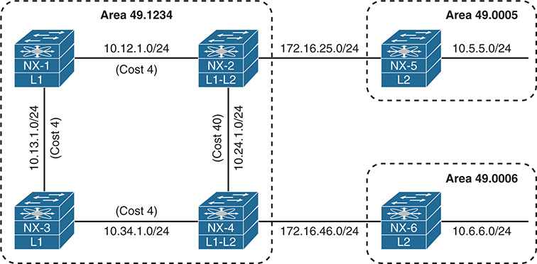
Figure 9-11 IS-IS InterArea Topology
The problem comes from the suboptimal routing that occurs when NX-1 tries to connect with 10.6.6.0/24 network, as it crosses the higher cost 10.24.1.0/24 network link. The same problem occurs for NX-3 connecting with the 10.5.5.0/24 network. Example 9-48 displays the suboptimal path taken by both NX-1 and NX-3.
Example 9-48 Suboptimal Path Selection
traceroute to 10.6.6.6 (10.6.6.6) from 192.168.1.1 (192.168.1.1), 30 hops max, 40 byte packets
1 10.12.1.2 (10.12.1.2) 1.95 ms 1.36 ms 1.397 ms
2 10.24.1.4 (10.24.1.4) 2.758 ms 2.498 ms 2.423 ms
3 172.16.46.6 (172.16.46.6) 4.037 ms * 4.103 ms
traceroute to 10.5.5.5 (10.5.5.5) from 192.168.3.3 (192.168.3.3), 30 hops max, 40 byte packets
1 10.34.1.4 (10.34.1.4) 1.826 ms 1.127 ms 1.249 ms
2 10.24.1.2 (10.24.1.2) 2.434 ms 2.461 ms 2.19 ms
3 172.16.25.5 (172.16.25.5) 5.262 ms
Example 9-49 displays the IS-IS database on NX-1 and NX-3. The attached bit ‘A’ is detected for NX-2 and NX-4. In essence, the attached bit provides a L1 default route toward the advertising L1-L2 router.
Example 9-49 IS-IS Database for Area 49.1234
IS-IS Process: NXOS LSP database VRF: default
IS-IS Level-1 Link State Database
LSPID Seq Number Checksum Lifetime A/P/O/T
NX-1.00-00 * 0x0000001D 0xC67A 1038 0/0/0/1
NX-2.00-00 0x00000021 0xAF03 1120 1/0/0/3
NX-3.00-00 0x0000001F 0xD222 1055 0/0/0/1
NX-4.00-00 0x00000021 0x94B5 1154 1/0/0/3
Now NX-1 and NX-2 must identify the closest router with the attached bit. Normally this is a manual process of cross-referencing the IS-IS database with the IS-IS topology table, but NX-OS does this for you automatically. The IS-IS topology table for NX-1 and NX-3 is displayed in Example 9-50.
Example 9-50 IS-IS Topology for Area 49.1234
IS-IS process: NXOS
VRF: default
IS-IS Level-1 IS routing table
NX-2.00, Instance 0x00000022
*via NX-2, Ethernet1/2, metric 4
NX-3.00, Instance 0x00000022
*via NX-3, Ethernet1/1, metric 4
NX-4.00, Instance 0x00000022
*via NX-3, Ethernet1/1, metric 8
0000.0000.0000.00, Instance 0x00000022, Default
*via NX-2, Ethernet1/2, metric 4
IS-IS process: NXOS
VRF: default
IS-IS Level-1 IS routing table
NX-1.00, Instance 0x0000001F
*via NX-1, Ethernet1/1, metric 4
NX-2.00, Instance 0x0000001F
*via NX-1, Ethernet1/1, metric 8
NX-4.00, Instance 0x0000001F
*via NX-4, Ethernet1/2, metric 4
0000.0000.0000.00, Instance 0x0000001F, Default
*via NX-4, Ethernet1/2, metric 4
Example 9-51 displays the routing table of NX-1 and NX-3. Notice that an entry does not exist for the 10.5.5.0/24 or 10.6.6.0/24 networks, so the default network is used instead. Notice that the default route correlates with the IS-IS topology table entry from Example 9-50.
Example 9-51 NX-1 and NX-3’s Routing Table
0.0.0.0/0, ubest/mbest: 1/0
*via 10.12.1.2, Eth1/2, [115/4], 00:07:05, isis-NXOS, L1
10.24.1.0/24, ubest/mbest: 1/0
*via 10.12.1.2, Eth1/2, [115/44], 00:07:05, isis-NXOS, L1
10.34.1.0/24, ubest/mbest: 1/0
*via 10.13.1.3, Eth1/1, [115/8], 00:04:39, isis-NXOS, L1
172.16.25.0/24, ubest/mbest: 1/0
*via 10.12.1.2, Eth1/2, [115/8], 00:07:05, isis-NXOS, L1
172.16.46.0/24, ubest/mbest: 1/0
*via 10.13.1.3, Eth1/1, [115/12], 00:04:39, isis-NXOS, L1
0.0.0.0/0, ubest/mbest: 1/0
*via 10.34.1.4, Eth1/2, [115/4], 00:07:32, isis-NXOS, L1
10.12.1.0/24, ubest/mbest: 1/0
*via 10.13.1.1, Eth1/1, [115/8], 00:05:11, isis-NXOS, L1
10.24.1.0/24, ubest/mbest: 1/0
*via 10.34.1.4, Eth1/2, [115/44], 00:07:32, isis-NXOS, L1
172.16.25.0/24, ubest/mbest: 1/0
*via 10.13.1.1, Eth1/1, [115/12], 00:05:11, isis-NXOS, L1
172.16.46.0/24, ubest/mbest: 1/0
*via 10.34.1.4, Eth1/2, [115/8], 00:07:32, isis-NXOS, L1
Suboptimal routing is corrected by route leaking, a technique that redistributes the L2 level routes into the L1 level. IS-IS route leaking is configured with the command distribute level-2 into level-1 {all | route-policy route-policy-name}. Example 9-52 displays the highlighted L2 route-leaking configuration.
router isis NXOS
net 49.1234.0000.0000.0002.00
distribute level-1 into level-2 all
router isis NXOS
net 49.1234.0000.0000.0003.00
distribute level-1 into level-2 all
Note
Route leaking normally uses a restrictive route map to control which routes are leaked; otherwise, running all the area routers in L2 mode makes more sense.
Let’s verify the change by checking the IS-IS database to see if the 10.5.5.0/24 and 10.6.6.0/24 networks are being advertised by NX-2 and NX-4 into IS-IS L1 for Area 49.1234. After that is verified, check the routing table to verify that those entries are added to the RIB. Example 9-53 displays the IS-IS Database with L2 Route Leaking.
Example 9-53 IS-IS Database with L2 Route Leaking
Extended IP : 10.6.6.0/24 Metric : 54 (D)
Extended IP : 10.5.5.0.24 Metric : 14 (D)
..
Extended IP : 172.16.25.0/24 Metric : 4 (U)
Extended IP : 10.6.6.0/24 Metric : 14 (D)
Extended IP : 10.5.5.0/24 Metric : 54 (D)
..
Extended IP : 172.16.46.0/24 Metric : 4 (U)
0.0.0.0/0, ubest/mbest: 1/0
*via 10.12.1.2, Eth1/2, [115/4], 06:41:03, isis-NXOS, L1
10.5.5.0/24, ubest/mbest: 1/0
*via 10.12.1.2, Eth1/2, [115/18], 00:01:02, isis-NXOS, L1
10.6.6.0/24, ubest/mbest: 1/0
*via 10.13.1.3, Eth1/1, [115/22], 00:01:20, isis-NXOS, L1
10.24.1.0/24, ubest/mbest: 1/0
*via 10.12.1.2, Eth1/2, [115/44], 06:41:03, isis-NXOS, L1
10.34.1.0/24, ubest/mbest: 1/0
*via 10.13.1.3, Eth1/1, [115/8], 06:38:37, isis-NXOS, L1
172.16.25.0/24, ubest/mbest: 1/0
*via 10.12.1.2, Eth1/2, [115/8], 06:41:03, isis-NXOS, L1
172.16.46.0/24, ubest/mbest: 1/0
*via 10.13.1.3, Eth1/1, [115/12], 06:38:37, isis-NXOS, L1
Example 9-54 verifies that NX-1 and NX-3 are forwarding traffic using the optimal path.
Example 9-54 Path Check After L2 Route Leaking
traceroute to 10.6.6.6 (10.6.6.6), 30 hops max, 40 byte packets
1 10.13.1.3 (10.13.1.3) 1.41 ms 1.202 ms 1.223 ms
2 10.34.1.4 (10.34.1.4) 2.454 ms 2.46 ms 2.588 ms
3 172.16.46.6 (172.16.46.6) 4.368 ms
traceroute to 10.5.5.5 (10.5.5.5), 30 hops max, 40 byte packets
1 10.13.1.1 (10.13.1.1) 1.73 ms 1.387 ms 1.409 ms
2 10.12.1.2 (10.12.1.2) 2.376 ms 2.814 ms 2.48 ms
3 172.16.25.5 (172.16.25.5) 4.38 ms * 4.702 ms
Redistribution
Redistributing into IS-IS uses the command redistribute [bgp asn | direct | eigrp process-tag | isis process-tag | ospf process-tag | rip process-tag | static] route-map route-map-name. A route-map is required as part of the redistribution process on Nexus switches. Every protocol provides a seed metric at the time of redistribution that allows the destination protocol to calculate a best path. IS-IS provides a default redistribution metric of 10.
Example 9-55 provides the necessary configuration to demonstrate the process of redistribution. NX-1 redistributes the connected routes for 10.1.1.0/24 and 10.11.11.0/24 in lieu of them being advertised with the IS-IS routing protocol. Notice that the route-map is a simple permit statement without any conditional matches.
Example 9-55 NX-1 Redistribution Configuration
redistribute direct route-map REDIST
!
route-map REDIST permit 10
The route is redistributed on NX-1 and is injected into the IS-IS database with the 10.1.1.0/24 and 10.11.11.0/24 prefix. The redistribution of prefixes is verified by looking at the LSPDB on other devices, such as NX-2, as shown in Example 9-56.
Example 9-56 Verification of Redistributed Networks
IS-IS Level-1 Link State Database
LSPID Seq Number Checksum Lifetime A/P/O/T
NX-1.00-00 0x00000008 0x2064 1161 0/0/0/3
Instance : 0x00000005
Area Address : 49.0012
NLPID : 0xCC
Router ID : 10.12.1.100
IP Address : 10.12.1.100
Hostname : NX-1 Length : 4
Extended IS : NX-1.01 Metric : 4
Extended IP : 10.1.1.0/24 Metric : 10 (U)
Extended IP : 10.11.11.0/24 Metric : 10 (U)
Extended IP : 10.12.1.0/24 Metric : 4 (U)
Digest Offset : 0
Summary
This chapter provided a brief review of the IS-IS routing protocols and then explored the methods for troubleshooting adjacency issues between devices, missing routes, and path selection.
The following parameters must match for the two routers to become neighbors:
IS-IS interfaces must be Active.
Connectivity between devices must exist using the primary subnet.
MTU matches.
L1 adjacencies require the area address to match, and the system ID must be unique between neighbors.
L1 routers can form adjacencies with L1 or L1-L2 routers, but not L2.
L2 routers can form adjacencies with L2 or L1-L2 routers, but not L1.
DIS requirements match.
IIH Authentication Type & Credentials (if any)
IS-IS is a link-state routing protocol that creates a complete map based on LSPs. Routes are missing from the routing database typically because of bad network design, mismatch of metric types, or through configurations that do not support L1-to-L2 route propagation. This chapter provided some common bad IS-IS designs and their solutions to prevent the loss of path information.
References
RFC 1195, Use of OSI IS-IS for Routing in TCP/IP and Dual Environments.
R. Callon. IETF, http://tools.ietf.org/html/rfc1195, December 1990.
RFC 3784, Intermediate System to Intermediate System (IS-IS) Extensions for Traffic Engineering (TE). Tony Li, Henk Smit. IETF, https://tools.ietf.org/html/rfc3784, June 2004.
Edgeworth, Brad, Aaron Foss, Ramiro Garza Rios. IP Routing on Cisco IOS, IOS XE and IOS XR. Indianapolis: Cisco Press, 2014.
Cisco. Cisco NX-OS Software Configuration Guides, http://www.cisco.com.