Chapter 5
Wireless Security and Identity Management with ISE
Due to the inherent open nature of Wireless LANs, an increasingly mobile workforce, and the explosion of new and diverse wireless devices, it has become imperative for organizations to implement the right mechanisms that allow monitoring and controlling network access.
Cisco Identity Services Engine (ISE) is an identity and access control policy management platform that at the most fundamental level enables organizations to enforce wireless access controls by implementing 802.1X, MAC authentication, and web-based authentication. But before diving into how to deploy and configure the most common ISE policies for wireless, in this chapter we focus first on understanding the underlying protocols and architecture.
Identity Management Building Blocks
Network Authentication, Authorization and Accounting (AAA) provide the fundamental security building blocks to answer the questions of “who/what are you?,” “what do you get access to?,” and finally, “when and what did you do?” AAA has been in use for so long that we tend to take for granted all the protocols that need to come into play to provide secure access, and thus we’ll spend some time talking about them.
802.1X
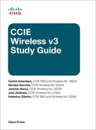
IEEE STD 802.1X-2010 is a protocol framework for Layer 2 access control that offers the capability to permit or deny network connectivity based on the identity of the end user or device. It uses a controlled/uncontrolled virtual port model, shown in Figure 5-1, to block general data over the controlled port before authentication completes successfully over the uncontrolled port that only allows EAP authentication traffic. After the controlled port is authorized, it unblocks to allow passing data.
On a wireless LAN, each association between a client and the access point creates a unique pair of 802.1X virtual ports. After authentication has completed, not only the flow of frames is permitted but cryptographic keys are generated to protect the frame transfer.
802.1X Components
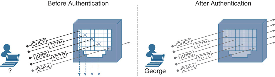
As specified in the standard and shown in Figure 5-2, 802.1X defines the following three required components:1
1 IEEE 802.1X-2010 - IEEE Standard for Local and metropolitan area networks—Port-Based Network Access Control, 2010
Supplicant: A client that requests access to network resources and submits credentials for authentication.
Authenticator: The network device that controls access to the network and facilitates the authentication process by relaying the credentials of the supplicant to the authentication server.
Authentication server: A server responsible for validating the credentials sent by the supplicant and determining the network access level that it should receive.
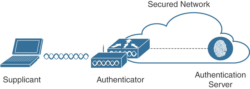
Figure 5-2 802.1X Components
EAP
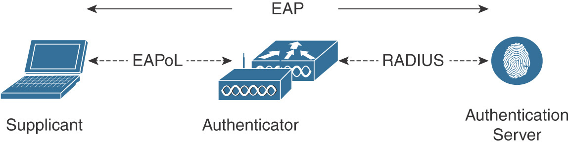
The Extensible Authentication Protocol (EAP), described in IETF RFC 3748, provides a flexible authentication framework which supports multiple methods that are negotiated and used to mutually authenticate the supplicant and the authentication server. EAP messages between the supplicant and the authenticator run directly over the data link layer using EAP over LAN (EAPoL) encapsulation as defined by the 802.1X standard. The authenticator will then extract the EAP payload from the EAPoL frame and relay the message to the authentication server by encapsulating it inside a RADIUS packet. This message exchange using different transport protocols is represented in Figure 5-3.
EAP is a request-response protocol in which the authenticator sends the request and the supplicant provides the response. This communication exchange uses four EAP type packets:
Request: This packet is sent by the authenticator to the supplicant and uses the type field to indicate what is being requested (that is, the identity of the supplicant or the EAP method to use).
Response: This packet is sent by the supplicant in response to a valid request from the authenticator.
Success: This packet is sent by the authenticator to the supplicant after successful completion of an EAP authentication method.
Failure: The authenticator will use this packet if it cannot authenticate the supplicant.
EAP Methods
EAP provides the flexibility to support different methods that define the type of credentials and how they are submitted from the supplicant to the authentication server using the EAP framework. Although multiple EAP methods are available, we will cover at a high level the three that are more commonly deployed.
EAP-FAST (EAP—Flexible Authentication via Secure Tunneling): Developed by Cisco and published as an informational document in IETF RFC 4851, EAP-FAST enables mutual authentication by using a shared secret, called Protected Access Credential (PAC), to establish a TLS tunnel that will secure the exchange of user authentication messages. As shown in Figure 5-4, EAP-FAST has three phases. During Phase 0 (which is optional and prevents manual out-of-band distribution of PACs), the PAC is automatically provisioned in-band on the supplicant using either an anonymous TLS handshake (using the Authenticated Diffie-Hellman Protocol) or via an authenticated tunnel using the server certificate. During Phase 1, the PAC is used to perform mutual device authentication, and a TLS tunnel is established. Finally, in Phase 2, user authentication credentials are passed securely within the TLS tunnel created in Phase 1. Several inner methods (MS-CHAPv2 for credentials or EAP-TLS for certificates) are available for EAP-FAST, which makes it very flexible.
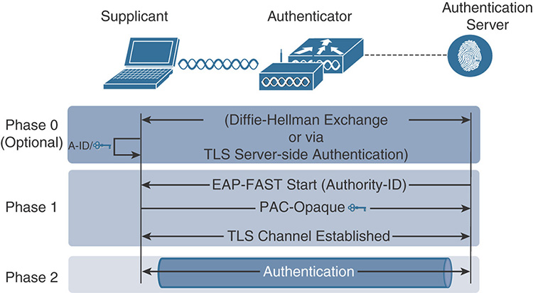
Figure 5-4 High-Level EAP-FAST Functionality PEAP (Protected EAP): This method, shown in Figure 5-5, relies on server-side TLS authentication to create an encrypted tunnel using a valid certificate that the authentication server sends to the supplicant at the beginning of the PEAP exchange. After the supplicant validates the certificate and the identity of the server has been authenticated, the TLS tunnel is established. Inside this tunnel, a new EAP negotiation takes place to authenticate the client using methods such as EAP-GTC, MS-CHAPv2, or EAP-TLS. PEAP is widely available on many client operating systems and is popular mainly because it does not require a client-side certificate (unless you do EAP-TLS inside the PEAP tunnel). It is even possible, in some operating systems, to skip the validation of the server-side certificate, which is a big security concern.
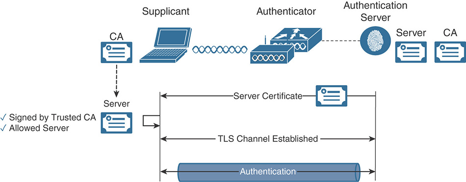
Figure 5-5 High-Level PEAP Functionality EAP-TLS (EAP—Transport Layer Security): Described in IETF RFC 5216, this method offers mutual authentication between the supplicant and the authentication server through the exchange and verification of X.509 certificates. This authentication process relies on not only the supplicant and authentication server having their own certificate, they each need to have a copy of the root certificate from the certificate authority (CA) that signed their peer’s certificate. During the EAP-TLS exchange, illustrated in Figure 5-6, the authentication server first submits its certificate to the supplicant to be validated. After the identity of the authentication server has been verified, the supplicant submits its certificate and the authentication server validates it, completing the process of mutual authentication. EAP-TLS is available as a standalone method, and also as an inner method for PEAP, which makes it even more secure because there is first an anonymous PEAP tunnel for encryption, and the full EAP-TLS exchange that follows is fully encrypted. That’s a TLS tunnel inside another TLS tunnel.
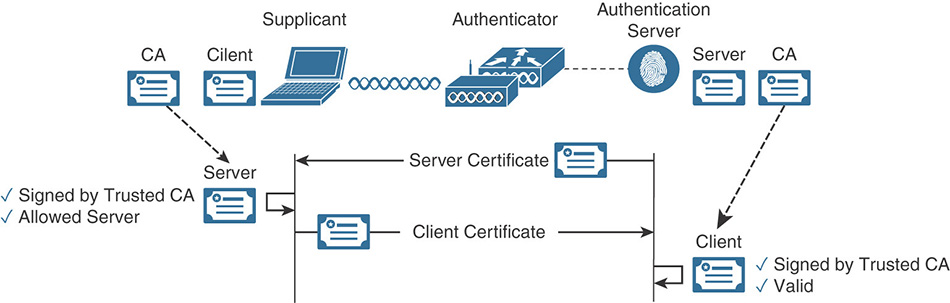
Figure 5-6 High-Level EAP-TLS Functionality
RADIUS
The Remote Authentication Dial-In User Service (RADIUS) is a protocol used to control network access defined in IETF RFC 2865 (authentication and authorization) and RFC 2866 (accounting).
RADIUS operates in a client/server model with the following entities:
Network Access Server (NAS): Responsible for passing user information to the RADIUS server and acting upon the response that is returned.
RADIUS Server: Responsible for processing the access request and returning all required parameters for the NAS to provide access to the user.
The transactions between the NAS and the RADIUS server are protected by the use of a shared secret and are transported over UDP on port 1812 (authentication) and 1813 (accounting). This communication takes place using six main packet types:
Access-Request: The NAS sends these packets to provide the server with the information required to assess whether the user will be granted access.
Access-Accept: The RADIUS server sends these packets to provide the NAS with the information required to allow access to the user.
Access-Reject: The RADIUS server uses these packets to notify the NAS that the information provided via the request is not acceptable.
Access-Challenge: The RADIUS server uses these packets to send the user a challenge requiring a response to obtain additional information.
Accounting-Request: The NAS sends these packets to deliver information about the user session for accounting purposes.
Accounting-Response: These packets help the RADIUS server notify the NAS that the Accounting-Request has been received and processed successfully.
RADIUS Attributes
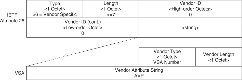
RADIUS Attribute-Value Pairs (AVP) are used to exchange information between the NAS and the authentication server to support the AAA process. They provide useful information about the access request being made, as well as a way for the authentication server to inform the NAS about the different parameters that need to be enforced.
These containers of information include a type, a length, and a value that defines them. Because the type field is an octet, up to 255 attributes can be used; some of them are already predefined and well known. One of these attributes, Vendor-Specific Attribute (attribute 26), enables vendors to communicate vendor-specific information by encapsulating their own extended attributes inside it, as illustrated in Figure 5-7.
CoA
In a standard RADIUS session, the NAS is required to initiate the exchange and does not support unsolicited messages. To provide more flexibility, the IETF RFC 5176 informational document defines enhancements that allow the authentication server to dynamically modify the authorization of a user session via Change-of-Authorization (CoA) messages.
CoA messages sent by the CoA client (RADIUS server) are transported over UDP using 3799 as the destination port. (Cisco implementation uses port 1700.) The NAS will reply with a CoA Acknowledgment (CoA-ACK) if it can successfully change the authorization for the user session, or a CoA Non-Acknowledgement (CoA-NAK) if the request is unsuccessful.
To target a CoA request to a particular session, the RADIUS server includes one or more of the following attributes:
Acct-Session-Id (IETF attribute 44)
Audit-Session-Id (Cisco vendor-specific attribute)
Calling-Station-Id (IETF attribute 31, which contains the host MAC address)
AAA Sequence
Now that we have covered the protocols that are used during the AAA process, let’s examine at a high level the operational sequence displayed in Figure 5-8, which shows how the components and protocols of 802.1X work together.
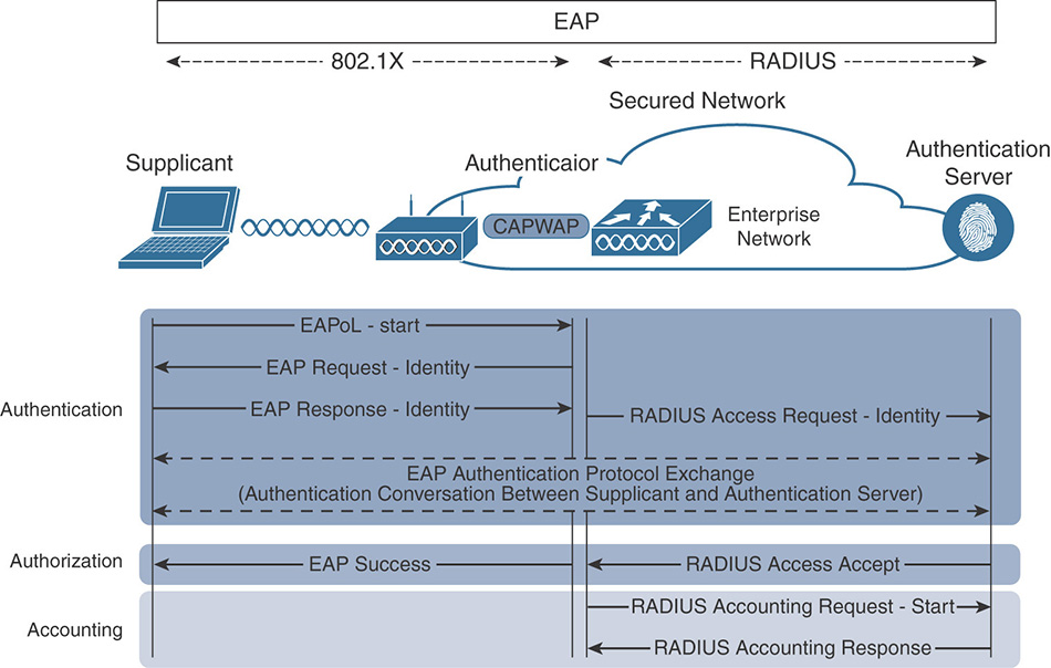
(Optional) The supplicant can initiate the authentication process by sending an EAPoL-Start message to the authenticator.
The authenticator, either replying to the supplicant start message or initiating the authentication exchange itself, sends an EAP-Request-Identity frame asking for the client’s identity.
The supplicant submits its identity (commonly referred as “outer identity”) to the authenticator, which forwards it to the authenticator server using RADIUS. For privacy, some devices will send “Anonymous” as the outer identity and will exchange their real username only inside the EAP tunnel. This outer identity is often the only thing authenticators (such as a WLC) will be able to use to refer to the user; they cannot read the true identity because the EAP tunnel is often encrypted between the supplicant and the RADIUS server.
The rest of the authentication exchange is defined by the specific EAP method (covered previously) that is negotiated between the supplicant and the authentication server. The actual method depends on the EAP types that are offered to the client based on how the RADIUS server is configured: the server suggests methods and the client chooses.
After the supplicant credentials are validated, the authentication server sends back a RADIUS Access-Accept message (if the credentials are invalid, it will reply with a RADIUS Access-Reject) that might contain additional attributes to further define the type of access that will be granted. The authenticator relays this message as an EAP Success frame to signal the supplicant that it has successfully completed the authentication and authorization process.
After the supplicant has been authorized and the policy has been applied, the authenticator sends information about the session to the authentication server via RADIUS Accounting-Request packets. Any future changes to the session will be communicated via interim updates.
In this exchange, the authenticator is responsible for relaying the EAP messages between the supplicant and the authentication server. It will process and copy the information contained in the EAPoL frame to an AVP (as suggested by IETF RFC 3850) in a RADIUS packet, and vice versa. The overall message mapping can be summarized as follows:
EAPoL-Response → RADIUS-Access Request
RADIUS-Access Challenge → EAPoL-Request
RADIUS-Access {Accept|Deny} → EAP {Success|Failure}
Identity Services Engine Deployment and Configuration
The Cisco ISE provides identity-based network access services that are organized into personas that are responsible for different functions. Depending on the scale of the deployment, these personas can be co-located on a single node (standalone deployment), where a node represents an instance of the ISE software, or distributed across a multi-node deployment (distributed deployment).
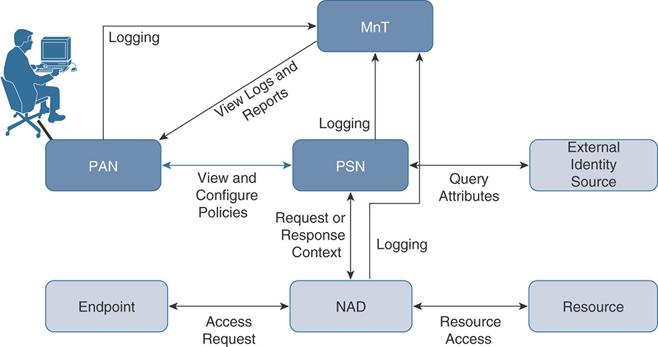
Three main personas are responsible for a specific set of services within the Cisco ISE architecture. Each ISE node can assume any or all of the following personas:
Policy Administration Node (PAN): This persona provides the main interface for handling all administrative tasks in the ISE deployment. It is responsible for managing and distributing all system and policy configuration to all other nodes. In a distributed deployment, you can have a maximum of two nodes that are assigned the Administration persona; one will be configured as primary active and the other as secondary standby. If the primary Administration node goes down, the secondary node needs to be manually promoted to take over.
Monitoring Node (MnT): This persona acts as a central repository for collecting and storing log messages from all the ISE nodes in the deployment. It correlates all this log information and provides capabilities for generating reports and alarms. There can be a maximum of two nodes with this persona taking on the primary and secondary role. In the case of the primary node going down, the secondary will automatically become the new primary node for the deployment.
Policy Service Node (PSN): This persona is responsible for assessing and making real-time policy decisions for network access, posture, client provisioning, profiling, guess access, and device administration services. In a distributed deployment you will typically have more than one PSN. High availability is achieved by placing multiple PSNs behind a load balancer or by allowing the NAS to make the decision to fall back to a different PSN in case the one in use goes down.
Figure 5-9 shows how the different personas communicate with each other.
Note
For the latest deployment size and scaling recommendations, refer to the most recent release of the Cisco Identity Services Engine Installation Guide at https://www.cisco.com/c/en/us/support/security/identity-services-engine/products-installation-guides-list.html.
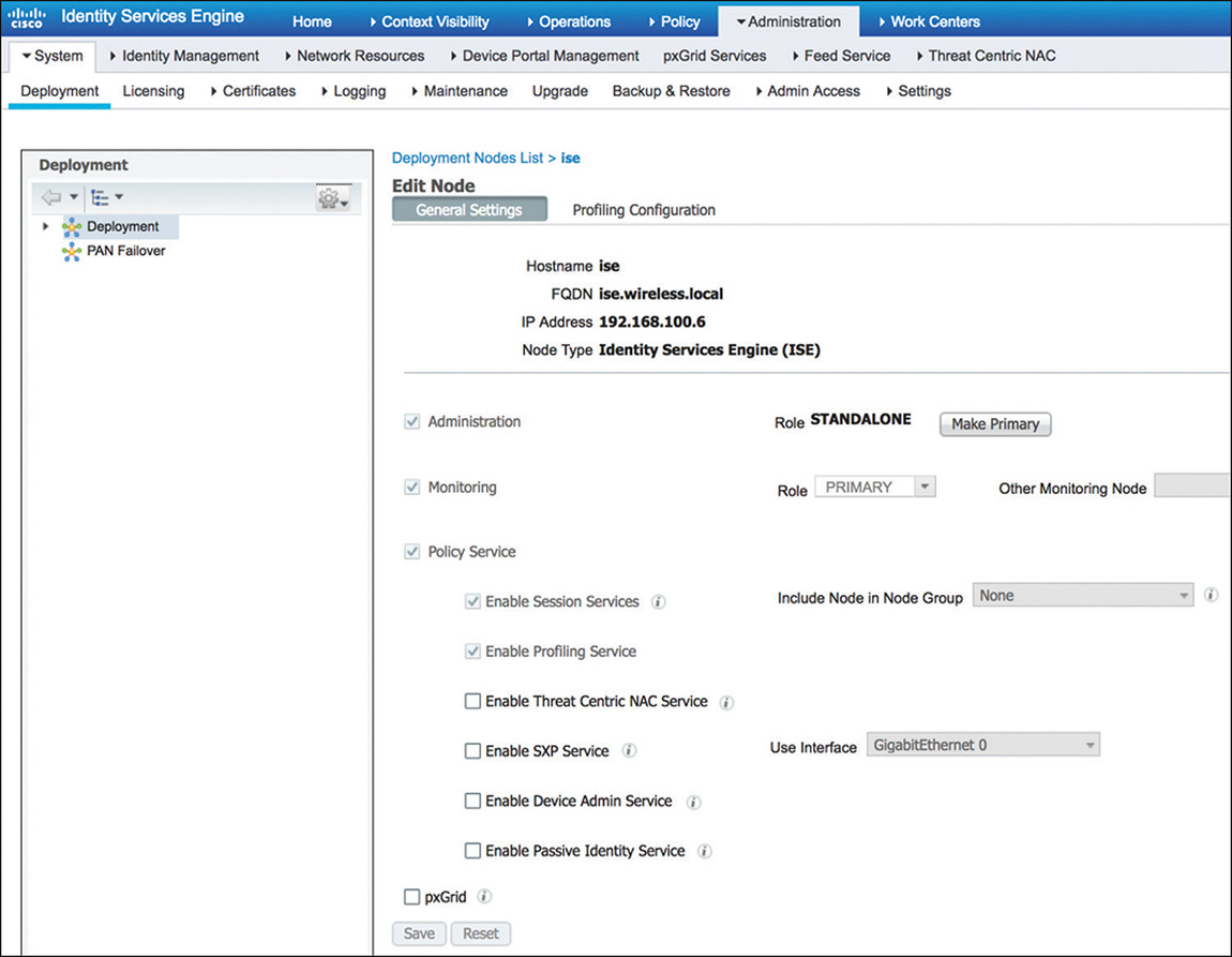
To edit the current personas and services assigned to a specific node, navigate to Administration > System > Deployment. From there, click the name (or check the check box next to the node you want to change and click Edit) to bring up the screen similar to the one shown in Figure 5-10 that will enable you to make the changes for the node.
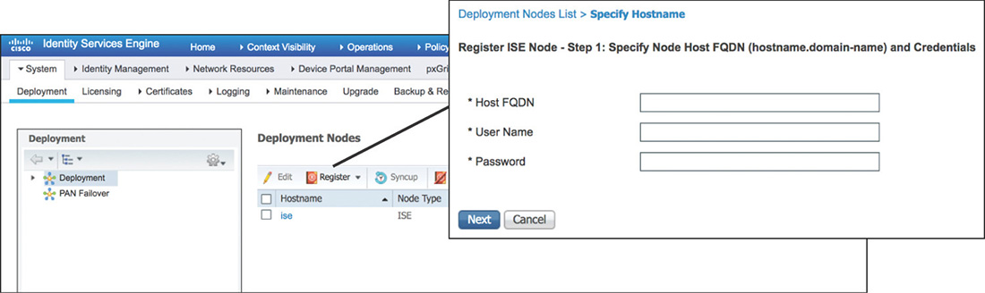
If you’re working on a distributed deployment, the first step is to promote the node from Standalone to Primary to be allowed to add any additional nodes. After the role is changed, you can go back and click Register to start the process of adding nodes by providing the required information as displayed in Figure 5-11. Keep in mind that the PAN will need to validate the certificates of the nodes that will be added, so before starting the registration process make sure that you have completed all the certificate provisioning tasks.
ISE Certificates
The Cisco ISE relies on a Public Key Infrastructure (PKI) to be able to perform authentication and to secure communications. There are two types of certificates in ISE:
System certificates: These certificates enable ISE to be identified and authenticated by other entities. Each node in the deployment holds its own system certificates, and by default they have a self-signed certificate that is created during installation. System certificates can be used for the following:
Admin: To authenticate the ISE Admin portal and secure inter-node communication.
EAP: For EAP authentication that uses SSL/TLS tunneling.
RADIUS DTLS: For RADIUS DTLS authentication (RADSec).
Portal: For securing communication with ISE portals.
pxGrid: For communicating with the pxGRID controller.
Trusted certificates: These certificates enable ISE to validate and authenticate the certificates received from users, devices, and other ISE nodes.
Certificates can be centrally managed via the Admin node. Three high-level steps must be completed to deploy certificates on ISE:
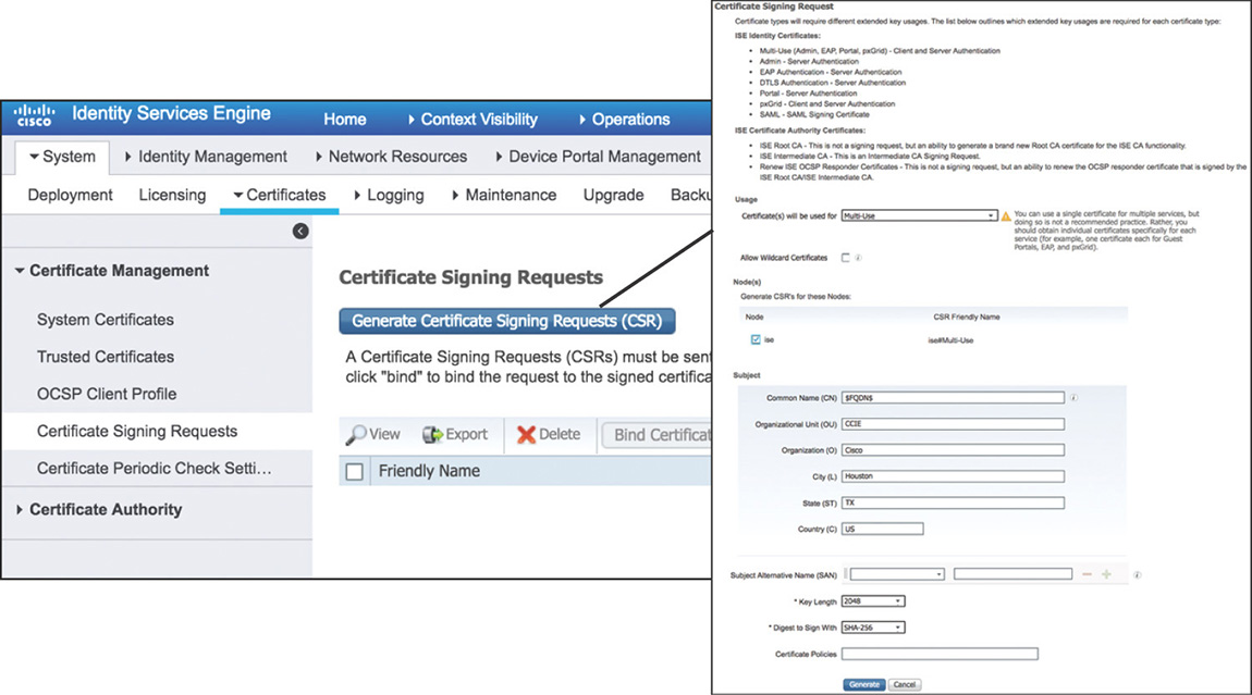
Step 1. Create a Certificate Signing Request (CSR) by navigating to Administration > System > Certificates > Certificate Signing Requests and entering the required values for the different certificate fields, as shown in Figure 5-12. You can generate a request per each ISE node, or alternatively you can request a wildcard certificate (a certificate that uses a * character in the left-most section of the Common Name or Subject Alternative Name) that would enable you to share it across multiple nodes. After the CSR is generated, it must be submitted and digitally signed by a certificate authority.
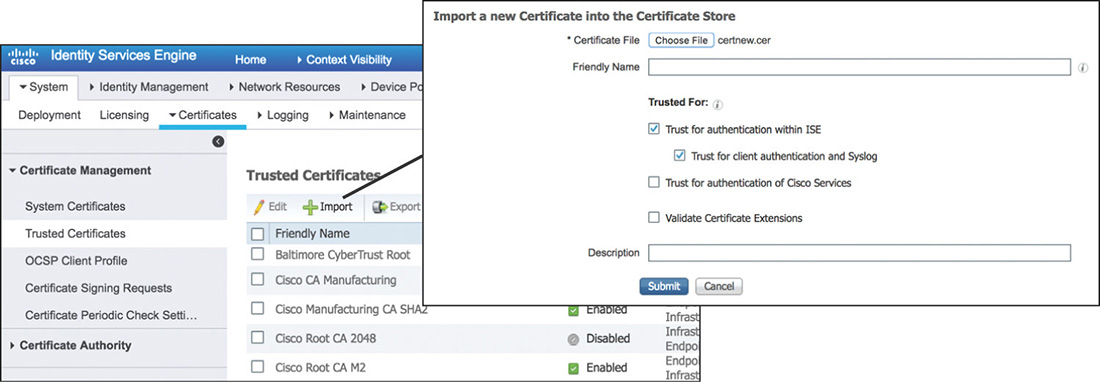
Step 2. Import the CA and sub-CA certificates into the Trusted Certificate Store by navigating to Administration > System > Certificates > Trusted Certificates as shown in Figure 5-13. Make sure that you check the Trust for Client Authentication and Syslog check box if the certificate will be used for client EAP authentication. Trusted certificates are managed and replicated automatically by the PAN to every node in the deployment.
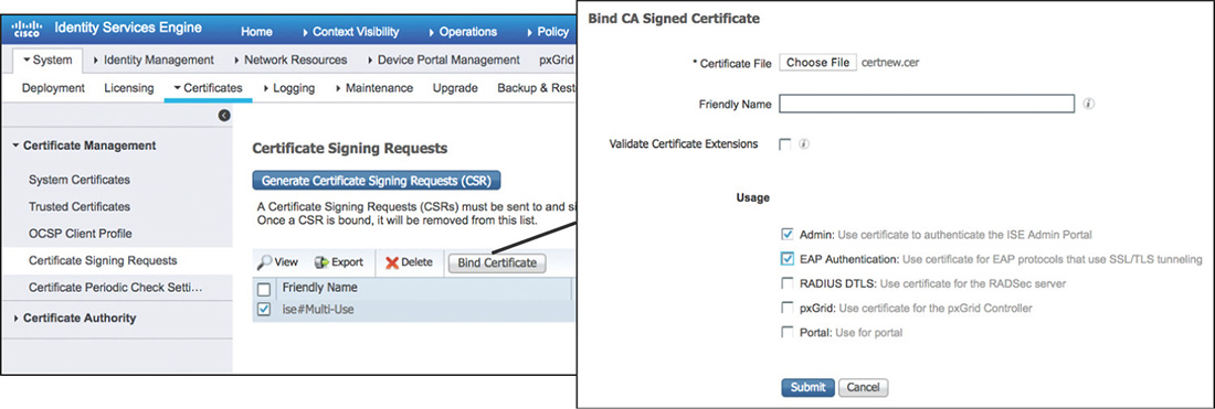
Step 3. Bind the CA signed certificate to the pending CSR by going to Administration > System > Certificates > Certificate Signing Requests and selecting Bind Certificate as shown in Figure 5-14. You will need to select the CA signed certificate file and specify the services for which this certificate will be used.
Network Access Policies
Cisco ISE provides network access services using a policy-based approach. Policies are built using rules that contain conditions. Cisco ISE will evaluate sequentially the rules within the policy, and if the conditions are satisfied it will apply the configured result actions.
Authentication Policy
Authentication policies define the rules that will be used to determine how to authenticate users and endpoints. These rules dictate what protocols will be allowed and what identity sources will be used for authentication. A rule-based authentication policy flow is represented in Figure 5-15.
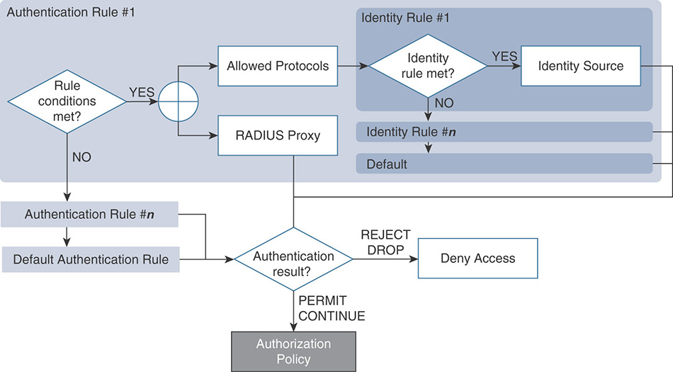
During the evaluation of the policy, rules are processed from top to bottom. When the conditions of a rule are met, processing stops, and the matching network access service and identity source are used.
You can configure the authentication policy by going to Policy > Authentication. This policy includes the elements highlighted in Figure 5-16.
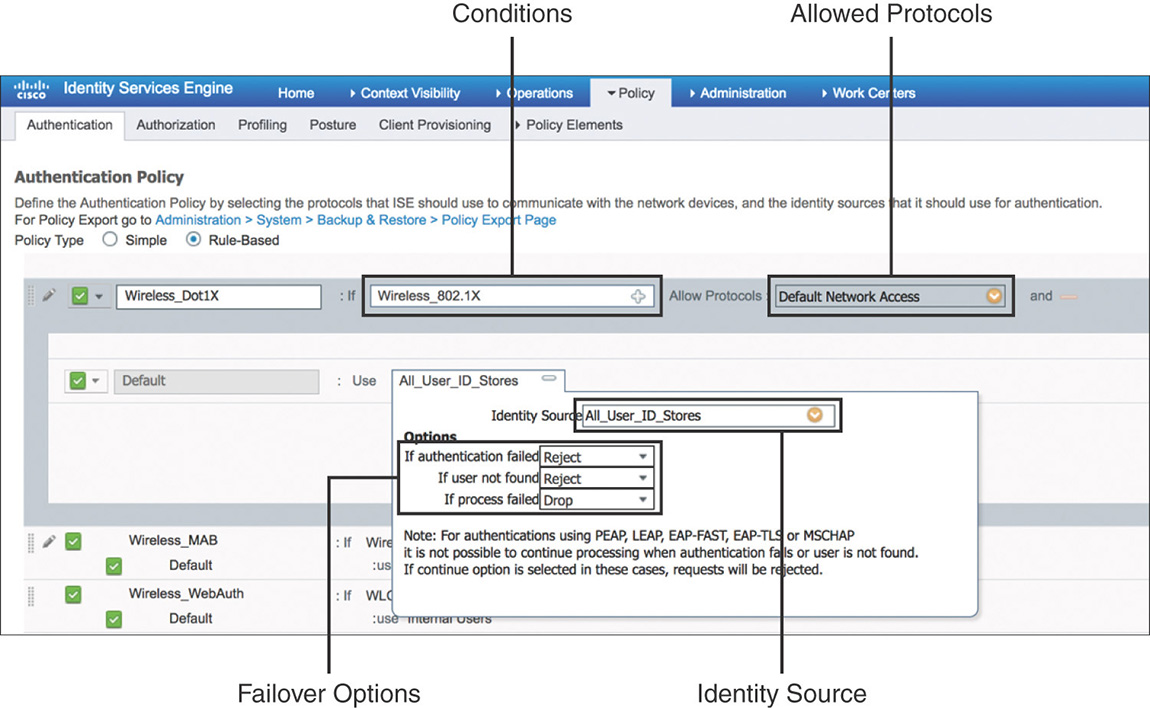
Conditions: Determine the attributes that need to be matched to process a particular rule. There are simple conditions that consist of a single attribute/operator/value set, and compound conditions that are made up of one or more simple conditions tied with an AND/OR operator. When adding conditions to a rule, you will be able to select between conditions from the existing library or create a new conditions, as shown in Figure 5-17.
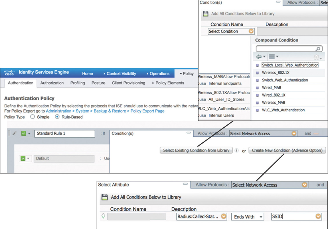
Figure 5-17 Authentication Rule Conditions Allowed protocols: Defines the protocols that ISE can use to communicate with endpoints requesting access to the network. You can customize the protocols allowed by going to Policy > Policy Elements > Results > Authentication > Allowed Protocol Services and creating a new service or leveraging the default network access service that is predefined and shown in Figure 5-18.
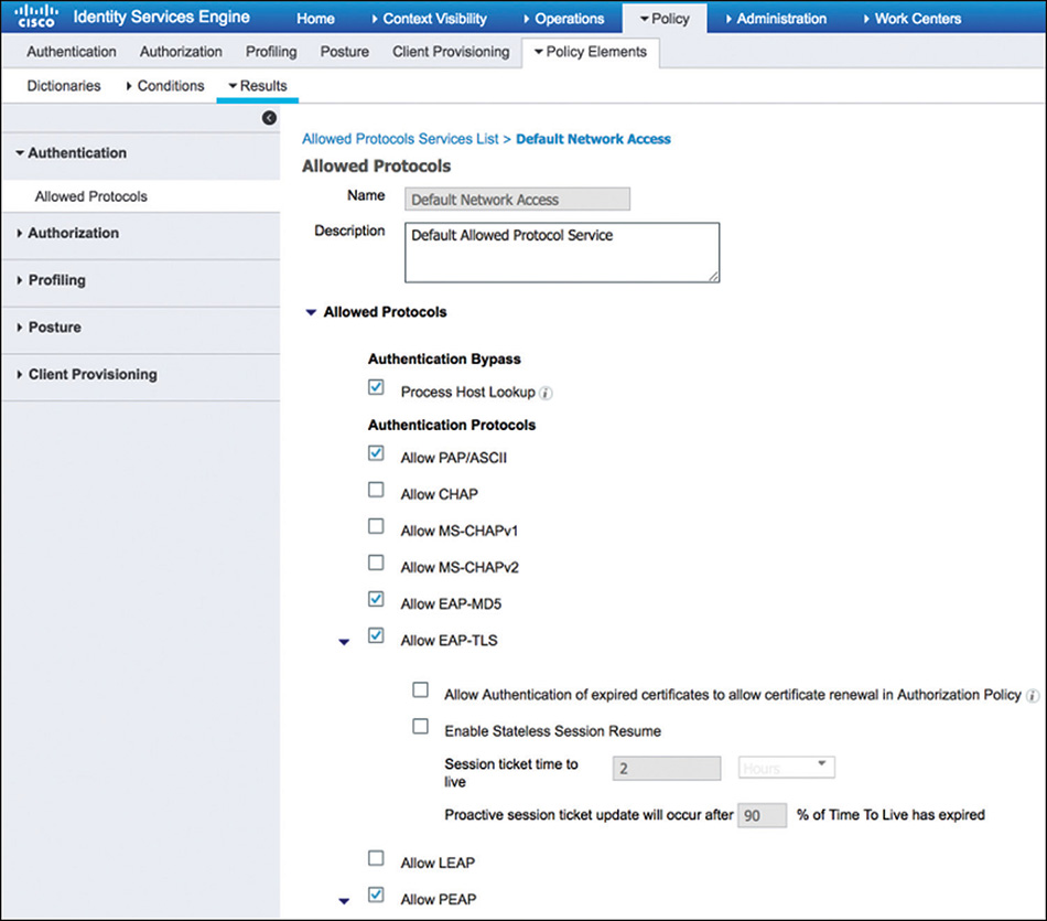
Figure 5-18 Allowed Protocols Identity Source: An identity source or an identity source sequence determines the user or endpoint repositories that will be used for authentication. This can include internal or external sources. To configure identity sources, navigate to Administration > Identity Management. Figure 5-19 shows a sample of external identity sources that could be referenced within an authentication policy.
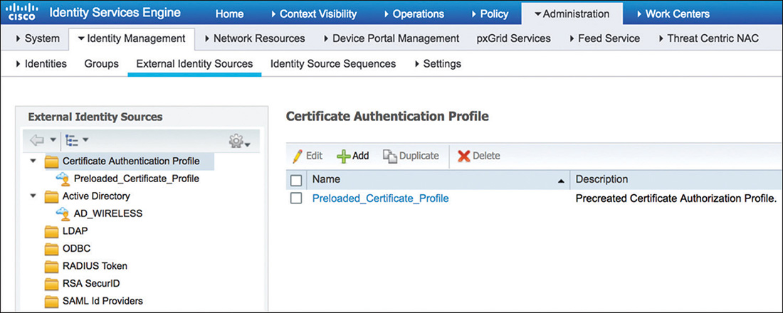
Figure 5-19 Identity Sources Failover Options: Define what action to take if authentication fails, if the user is not found, or if the process fails. One of the main use cases when we use these failover option is to implement MAC Authentication Bypass (MAB): if the MAC address is unknown, authentication can still succeed and the session will move to authorization. Note that the option to continue if the user is unknown doesn’t work well with wireless dot1x: wireless dynamic encryption keys won’t be able to be derived without the proper keying material.
After Cisco ISE concludes processing the authentication policy and the result is not an access reject, it moves to evaluate the rules in the authorization policy.
Authorization Policy
The authorization service in Cisco ISE is defined via a rule-based policy that allows controlling user access to the network and its resources. Within the authorization policy are two sets of rules that you can configure:
Standard: Meant to be used as the main set of rules for normal operation.
Exceptions: Intended to be used in the short term to meet a specific exception requirement.
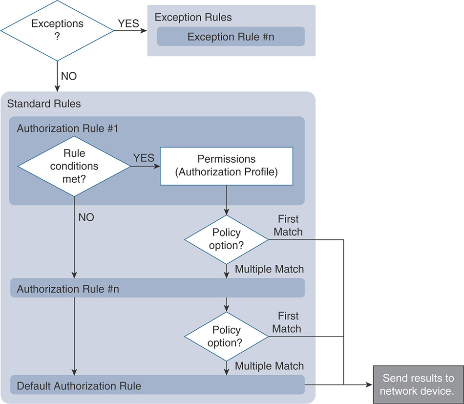
Similar to authentication rules, authorization rules are processed from the top down. Exception rules, if defined, will be processed first before moving to the standard rules. Additionally, ISE can be directed to use either the first matched rule or to match and apply the results of multiple rules. The high-level authorization policy flow is shown in Figure 5-20.
You can configure the authorization policy by going to Policy > Authentication. It contains rules that contain conditions and permissions, as shown in Figure 5-21.
Conditions: Enable you to set the identity group and additional attributes that need to match in order to process the rule.
Permissions: Enforced by authorization profiles. Authorization profiles act as containers that let you choose the attributes to be returned when a RADIUS request is accepted. These authorization profiles are defined by going to Policy > Policy Elements > Results > Authorization > Authorization Profiles. A sample is displayed in Figure 5-22.
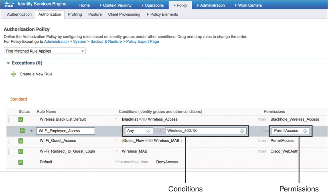
Figure 5-21 Authorization Policy Configuration 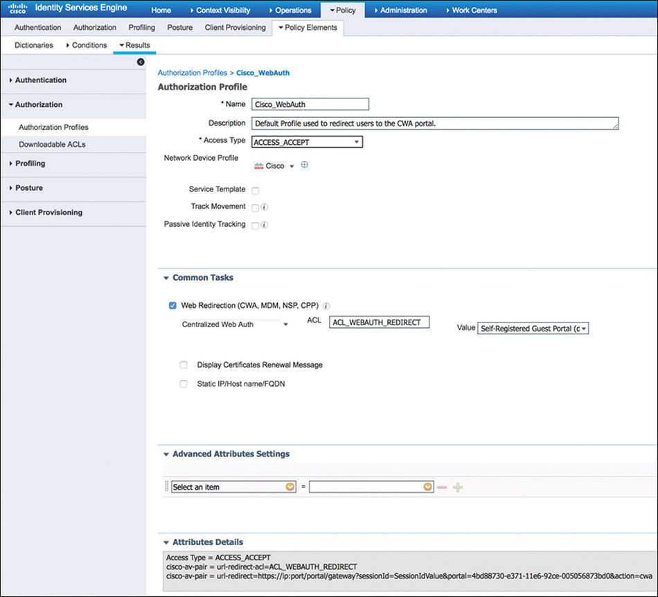
Figure 5-22 Authorization Profile
Profiling Policy
Profiling in Cisco ISE is implemented via profiling policies and is a key service that helps identify, locate, and determine the capabilities of endpoints that connect to the network. The profiling service is enabled by default on the PSNs along with some of the basic probes (RADIUS, DHCP, NMAP) that are responsible for collecting the endpoint attributes. This can be viewed or edited by going to Administration > System > Deployment and selecting the desired PSN.
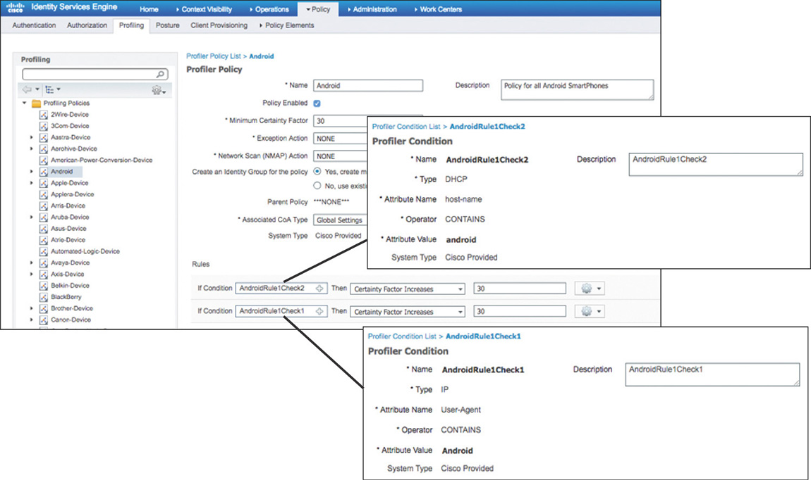
To profile a device, Cisco ISE uses the various collected attributes for each endpoint and tries to determine the device type by matching them to built-in or user-defined profiling policies that can be configured by going to Policy > Profiling. These profiling policies, shown in Figure 5-23, contain one or more rules that if matched will increase the certainty factor; the profile for which the endpoint has the highest cumulative factor is the one that will be assigned. The conditions that are used in the rules are available by navigating to Policy > Policy Elements > Conditions > Profiling.
Although different types of attributes are collected, the most common ones used for profiling clients are based on RADIUS, MAC OUI, DHCP, and HTTP.
The profiling service plays an important supporting role for the authorization process. Authorization rules can leverage the profiling policy applied to an endpoint as an additional condition to match. This can be done in two ways:
Creating a matching identity group, as shown in Figure 5-24, where endpoints will be placed after they are profiled.
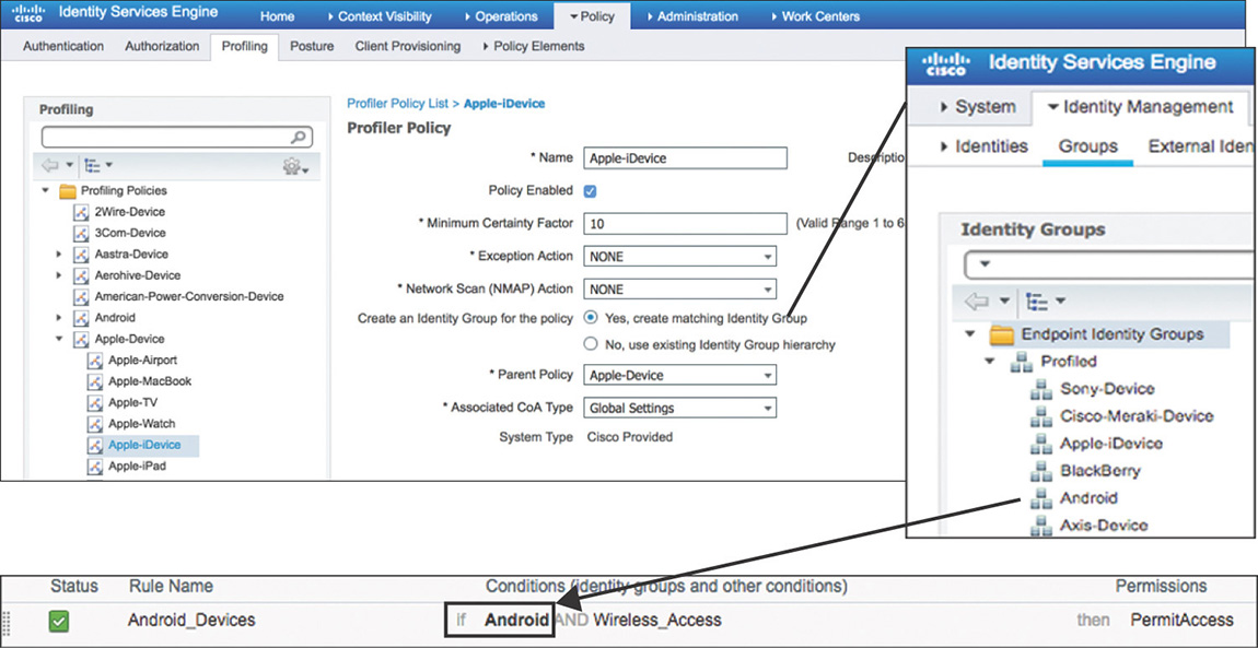
Figure 5-24 Profiling Policy with Matching Identity Group Using logical profiles that act as containers for multiple profiling policies, as displayed in Figure 5-25.
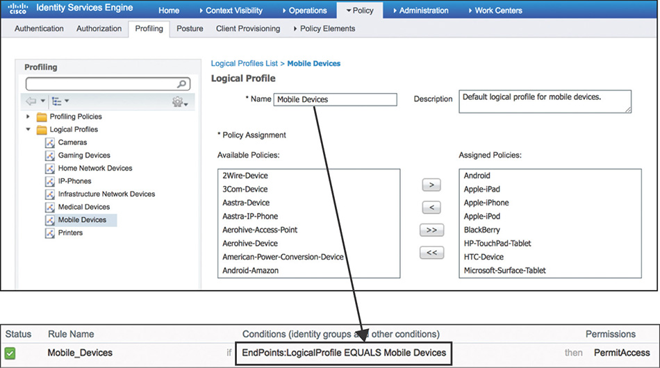
Figure 5-25 Profiling Policy Leveraging Logical Profiles
Guest Access
Cisco ISE has the capability to provide guest access to users, such as visitors, contractors, and customers, by allowing them to perform web authentication using a guest portal. Two main services cover the full life cycle of guest access: guest services, which focus on the customizable portals and guest types, and sponsor services, which deal with sponsor portals and sponsor groups.
Guest Services
Cisco ISE guest services allow hosting multiple customizable portals. Three types of portals, for which the high level flow is shown in Figure 5-26, can be created:
Hotspot Guest Portal: Guests can access the network without requiring credentials, but you can add a welcome message and an Acceptable Usage Policy (AUP).
Sponsored Guest Portal: The guest portal requires guests to have credentials to gain access. Sponsors will be responsible for creating the guest accounts because guests cannot create their own accounts.
Self-Registered Guest Portal: Guests are allowed to provide information to automatically create their own account, which they will use to log in to the portal. Having sponsor approval can be added as an optional requirement.
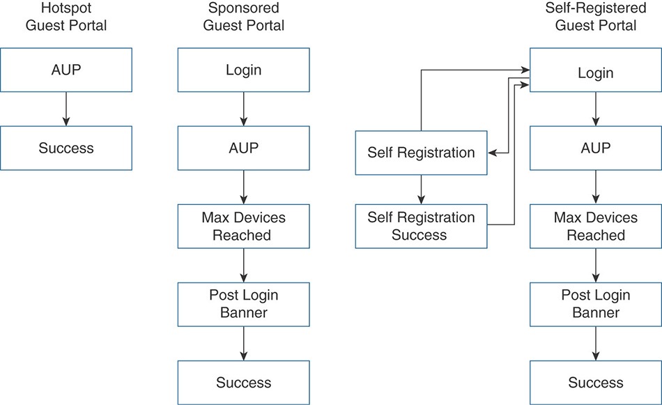
Figure 5-26 Guest Portal Types
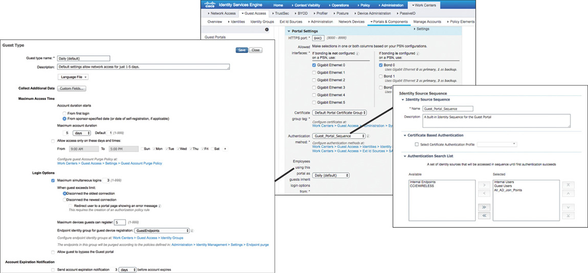
When implementing the sponsored or self-registered guest portal options, the guest accounts that will be created need to be associated with a guest type. You can configure guest types by going to Work Centers > Guest Access > Portals & Components > Guest Types, and they allow you to specify different access privileges such as maximum access time, logon options, and account expiration notifications. One thing to keep in mind is that the guest portal is not exclusive for guest users; it can be configured to use multiple internal or external identity sources to validate the credentials that are submitted via the portal. Both of these settings for the guest portal are shown in Figure 5-27.
Sponsor Services
The Cisco ISE sponsor portal enables you to create, edit, suspend, and reinstate guest user accounts. Configuration of the sponsor portal is done through the Work Centers > Guest Access > Portals & Components > Sponsor Portals section.
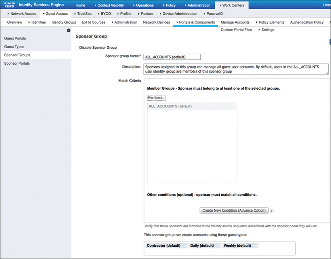
To control access to the sponsor portal, different levels of sponsor responsibility can be added and assigned to internal employees who create accounts for guests. These sponsor groups control the guest types that can be created by members of the group, as well as which accounts they can view and edit. Access to sponsor groups is assigned by adding members, which can be internal or external user groups. The configurable settings for a sponsor group are shown in Figure 5-28.
ISE Integration with Active Directory
Active Directory (AD) is leveraged by most organizations as their main identity source. By allowing you to integrate AD with ISE, objects such as groups and directory attributes become elements that can be used in the authorization policy rules.
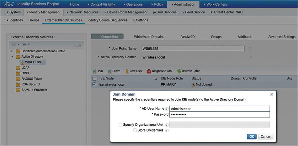
To integrate with Active Directory, on Cisco ISE navigate to Administration > Identity Management > External Identity Sources > Active Directory. From there you need to add a new AD connection by specifying the domain name. Then, each relevant Cisco ISE node must be selected to request the join process, as shown in Figure 5-29. It is not mandatory to be a domain administrator to perform the join process; the account just needs to be able to search the domain, create the machine accounts for the ISE nodes, and set their attributes.
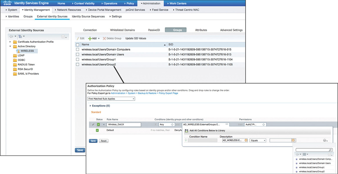
After you have joined the domain, you can retrieve and configure AD groups, making them available to be used as additional attributes in conditions inside the authorization policy rules, as shown in Figure 5-30.
Note
Further details on the key features and configuration of Active Directory in Cisco ISE 2.x can be found at https://www.cisco.com/c/en/us/td/docs/security/ise/2-3/ise_active_directory_integration/b_ISE_AD_integration_2x.pdf.
Device Administration Policies
Cisco ISE can provide Device Administration services (TACACS+) allowing administrators to securely log in to network devices to perform configuration and maintenance tasks.
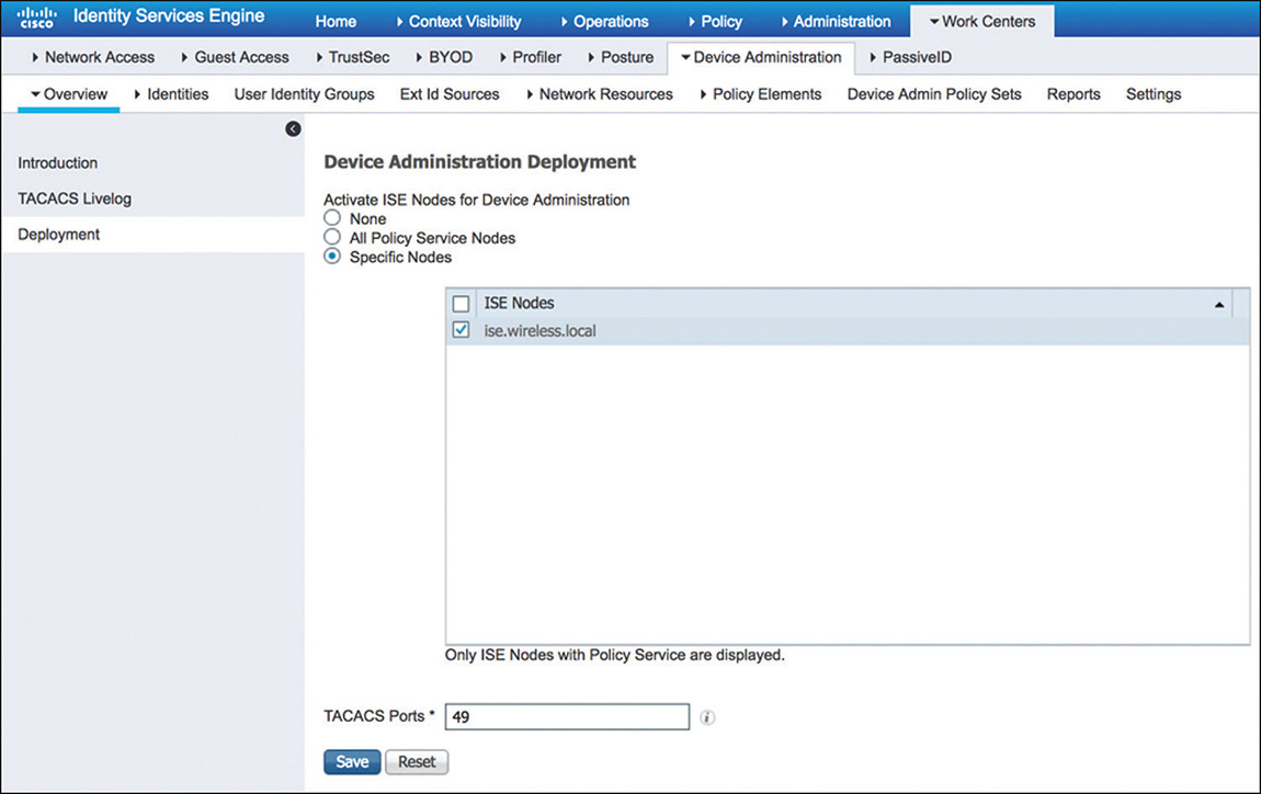
One way to enable TACACS+ is to navigate to Work Centers > Device Administration > Overview > Deployment, and from there select the nodes that will provide the service, as shown in Figure 5-31. The alternative method is to go to Administration > System > Deployment, and from there select the desired PSNs and enable the Device Admin Service under the General Settings for the node.
After the device admin service is enabled, you will have to configure the device admin policy, which is structured with the components that are shown in Figure 5-32.
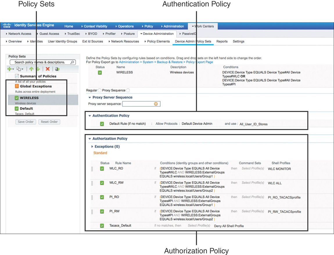
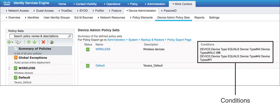
Policy Sets
Policy sets are enabled by default for the Device Administration service. They act as hierarchical containers to logically group the authentication and authorization policies. Each policy set will have conditions, as shown in Figure 5-33, that are evaluated to determine whether there is a match. If the conditions are met, the authentication and authorization policies within that set are used.
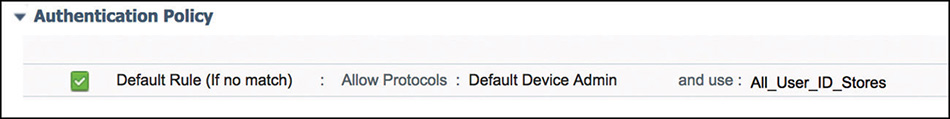
Authentication Policy
Authentication policies follow the same logic as their counterpart for network access authentication. As shown in Figure 5-34, they include rules that determine which protocols will be allowed and the identity source to use to validate the credentials provided.
Authorization Policy
Although the authorization policy, such as the one displayed in Figure 5-35, follows the same common structure using rules and conditions to determine the access that will be granted, there are two elements that are unique to the Device Administration service:
Command Sets: Enforce a specific list of commands that can be executed by a device administrator (not used by WLCs or Prime Infrastructure).
TACACS+ Profiles (Shell Profile): Control the session of the device administrator by sending back a set of attributes that limits the actions that may be performed on the network device. To configure TACACS+ Profiles, navigate to Work Centers > Device Administration > Policy Results > TACACS Profiles.
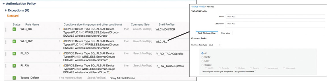
Figure 5-35 Device Administration Authorization Policy
Configuring ISE for Wireless
Now that we have covered some of the basics, it is time to go through some of the most common wireless flows that can be implemented using Cisco Identity Services Engine. This should serve as a foundation to build on and give you an idea of how to later generate more advanced security policies.
Keep in mind that so many options and combinations exist that it will be hard to cover them all in this chapter. We will focus on the base configuration that is critical for making things work. Additionally, several components are preconfigured to simplify the initial deployment process that we will highlight where relevant.
Common Configuration
One of the first things that needs to be configured is to enable communication between the WLC and Cisco ISE. This must be completed on both sides.
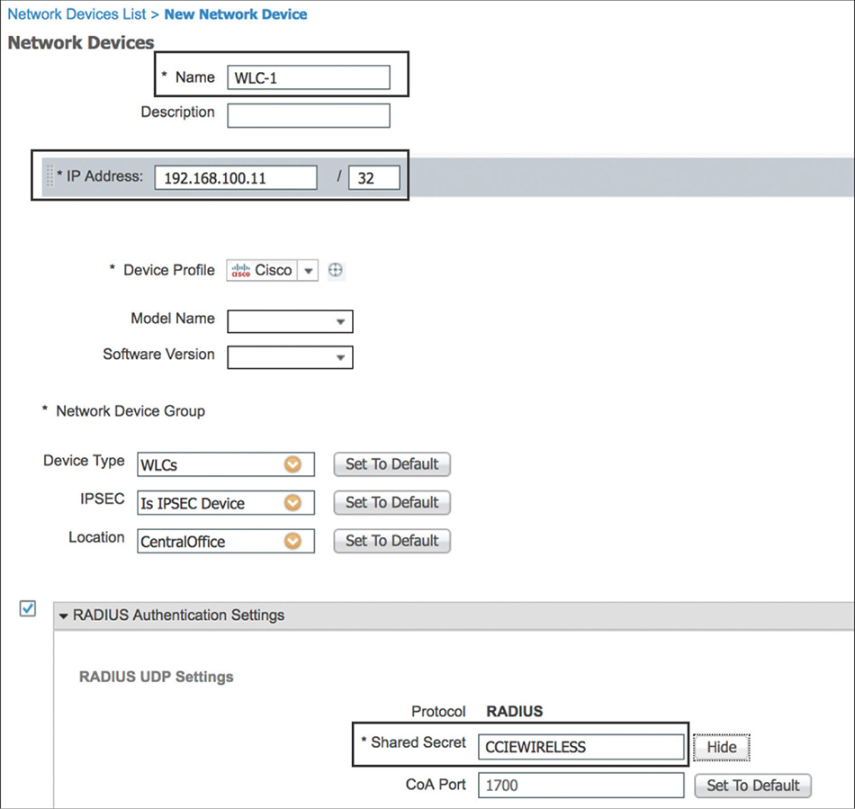
To configure ISE, go to Administration > Network Resources > Network Devices and add the WLC as a new network device. The name and IP address, and enabling RADIUS and TACACS+ with a shared secret is the minimum configuration to be entered, as depicted in Figure 5-36. Optionally, other attributes, such as Network Device Group membership (that is, Device Type or Location), although not mandatory, could become useful in building more complex conditions in the different types of policies.
On the WLC, Cisco ISE must be defined in multiple places, but the steps are fundamentally the same. You can configure ISE as a RADIUS Authentication and Accounting server by going to SECURITY > RADIUS > {Authentication | Accounting} as shown in Figure 5-37, and as a TACACS+ AAA server by going to SECURITY > TACACS+ > {Authentication | Authorization | Accounting}.
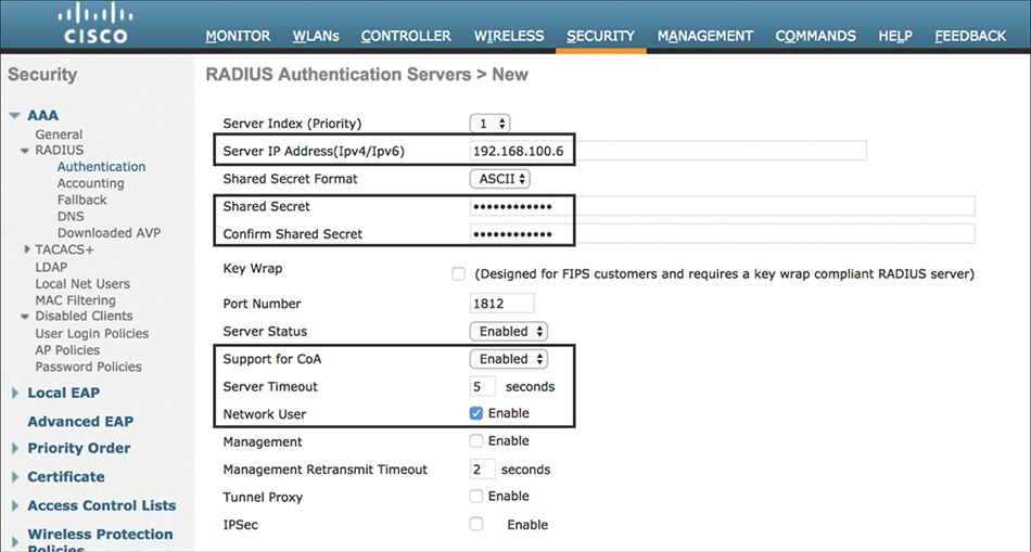
Note
Certain flows in ISE require you to issue a Change of Authorization (CoA) to the WLC to force the user to reauthenticate. Make sure that you enable Support for CoA (Support for RFC 3576 in older versions of code) to allow the WLC to process the CoA packet received from ISE.
Optionally, some recommended configuration settings should be considered when integrating the WLC with ISE:
Note
Additional information regarding best practices that are applicable to configuring ISE as a RADIUS server can be accessed at Cisco Wireless LAN Controller (WLC) Configuration Best Practices, https://www.cisco.com/c/en/us/td/docs/wireless/controller/technotes/8-6/b_Cisco_Wireless_LAN_Controller_Configuration_Best_Practices.html.
The Server Timeout by default is 2 seconds; this may be short for a large enterprise, especially if doing authentication and membership lookups against external identities such as Active Directory. A minimum value of 5 seconds is recommended to prevent the authentication process from timing out.
Configure RADIUS Fallback Mode so that the primary RADIUS server is used when it is back online. Without this option, when the WLC flags a RADIUS server as down, it will failover to the next active backup RADIUS server and will continue to use it, even if the primary server becomes available. There are two modes for fallback: Selecting Active, which is shown in Figure 5-38, causes the WLC to periodically send probe authentication requests to the RADIUS server and mark the server alive only when it receives a response. When configuring Passive, the WLC reverts to the primary server after a predefined interval of time.
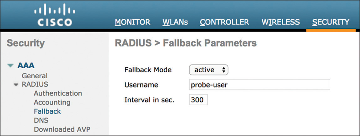
Figure 5-38 WLC RADIUS Fallback Mode By default, RADIUS Aggressive Failover is enabled, which causes the WLC to flag the server as not responding if it fails to get a response back for a single client (which could be due to the server doing a silent discard). By disabling this setting, the WLC will failover to the next server only if there are three consecutive clients that fail to receive a response from the RADIUS server. This change can be performed only via the CLI with the config radius aggressive-failover disable command.
On a WLAN, the Session Timeout by default is 1800 seconds, which is the interval before client reauthentication is enforced. This short interval could create an unnecessary load on the ISE server, so it is recommended, depending on the deployment requirements, to consider changing this timer to at least 7200 seconds, as shown in Figure 5-39.
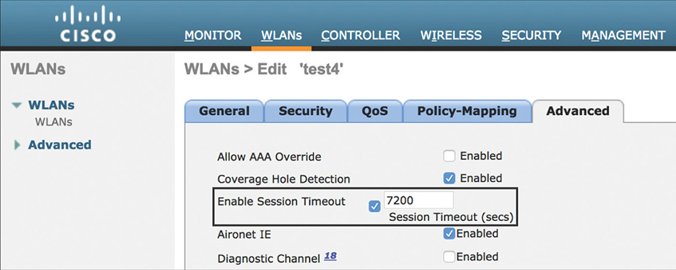
Figure 5-39 WLAN Session Timeout
It is worth mentioning that it is possible to test and troubleshoot RADIUS connectivity and WLAN authentication issues without the need of an actual wireless client by issuing the test aaa radius username username password password wlan-id wlan-id [ apgroup apgroupname server-index server-index ] command. This command will send an access request to the RADIUS server for client authentication, and the response to the test can be displayed by entering the test aaa show radius command. Note that this test uses PAP as an authentication method and not an EAP method (to avoid dealing with certificates during your simple test), and PAP might not be allowed by your authentication policy on ISE. Example 5-1 shows how these commands can be executed and how they display the associated AVPs that are sent or received from the AAA server.
Example 5-1 Test AAA RADIUS Command
(WLC) >test aaa radius username testuser password testpwd wlan-id 1

Radius Test Request
  Wlan-id........................................ 1
  ApGroup Name................................... none

  Attributes                      Values
  ----------                      ------
  User-Name                       testuser
  Called-Station-Id               00-00-00-00-00-00:8021Xssid
  Calling-Station-Id              00-11-22-33-44-55
  Nas-Port                        0x00000001 (1)
  Nas-Ip-Address                  100.127.100.10
  NAS-Identifier                  0x574c4331 (1464615729)
  Airespace / WLAN-Identifier     0x00000001 (1)
  User-Password                   testpwd
  Service-Type                    0x00000008 (8)
  Framed-MTU                      0x00000514 (1300)
  Nas-Port-Type                   0x00000013 (19)
  Tunnel-Type                     0x0000000d (13)
  Tunnel-Medium-Type              0x00000006 (6)
  Tunnel-Group-Id                 0x00000064 (100)
  Cisco / Audit-Session-Id        647f640a000000175b7debc8
  Acct-Session-Id                 5b7debc8/00:11:22:33:44:55/1271

test radius auth request successfully sent. Execute 'test aaa show radius' for
  response

(WLC1) >test aaa show radius
Radius Test Request
  Wlan-id........................................ 1
  ApGroup Name................................... none
Radius Test Response

Radius Server            Retry Status
-------------            ----- ------
192.168.100.6            1     Success

Authentication Response:
  Result Code: Success

  Attributes                      Values
  ----------                      ------
  User-Name                       testuser
  State                           ReauthSession:647f640a000000175b7debc8
  Class                           CACS:647f640a000000175b7debc8:ise/323248099/95
  Tunnel-Type                     0x0000000d (13)
  Tunnel-Medium-Type              0x00000006 (6)
  Tunnel-Group-Id                 0x000000c8 (200)
Wireless RADIUS Attributes
In a wireless network, specific RADIUS attributes can be used to exchange information between the WLC and ISE in regard to the users or endpoints that are trying to gain access. In addition to this section or the configuration guides, one good place to review these attributes is to go to Policy > Policy Elements > Dictionaries in ISE.
Table 5-1 identifies a subset of the most common RADIUS attributes that are sent by the WLC to ISE as part of the access-requests. These attributes would be used to help build our compound conditions for rules in the authentication and authorization policies.
Table 5-1 Authentication Attributes Sent in Access-Request Packets
|
Attribute ID |
Attribute Name |
Description |
IETF |
1 |
User-Name |
Indicates the name of the user to be authenticated. It could be either an actual username or the MAC address of the device. Example: Radius:NAS-IP-Address CONTAINS DomainName This condition can match on request from users for which their username is part of a specific domain. |
|
4 |
NAS-IP-Address |
This attribute indicates the IP address of the WLC that is requesting authentication of the user. Example: Radius:NAS-IP-Address EQUALS 100.127.100.10 This condition can be used to match by IP address requests coming from specific WLCs |
|
6 |
Service-Type |
Indicates the type of service the user has requested. The values used typically by the WLC are the following: Login (1): Used for local web authentication Framed (2): Used when performing 802.1X Call Check (10): Used when doing MAC authentication Example: Radius:NAS-Port-Type EQUALS Framed This condition will match on 802.1X requests. |
|
30 |
Called-Station-ID |
This attribute will normally store the AP MAC address appending the SSID (<xx-xx-xx-xx-xx-xx>:<ssid>). The behavior can be modified via configuration on the WLC. Example: Radius:Called-Station-ID ENDS WITH ssid1 This condition will match on request of users connecting to and specific SSID. |
|
31 |
Calling-Station-ID |
This attribute contains the MAC address of the client. |
|
32 |
NAS-Identifier |
This attribute contains a string identifying the WLC originating the Access-Request, typically being the WLC hostname. The value can be modified at the AP Group or WLAN level. Example: Radius:NAS-Identifier EQUALS WLC1 This condition can be used to match by hostname request coming from specific WLCs. |
|
61 |
NAS-Port-Type |
Indicates the type of the physical port of the NAS authenticating the user. For a WLC this value will always be Wireless - IEEE 802.11 (19). Example: Radius:NAS-Port-Type EQUALS Wireless - IEEE 802.11 This condition will match on request initiated by a WLC. |
Airespace |
1 |
Airespace-Wlan-Id |
Every WLAN created on the WLC has a numeric WLAN ID. This attribute sends the ID value matching the WLAN that the client is connecting to. Example: Airespace:Airespace-Wlan-Id EQUALS 2 This condition will match on request for users connecting to a specific WLAN. One disadvantage to this attribute is if the WLAN ID does not match on an SSID spread across multiple controllers. |
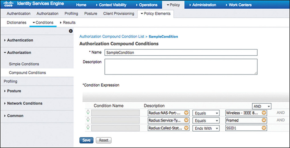
In Figure 5-40 we can see an example of how we can use a combination of these attributes to hone in to a particular access request. In this particular case it would be for wireless users connecting using 802.1X to SSID1.
In contrast, the attributes shown in Table 5-2 are sent by ISE and honored by the WLC in the access-accept packets. These attributes can be used to build the authorization profiles (permissions) that will determine the type of access that will be granted. There are three main groups of these attributes.
Table 5-2 Authentication Attributes Honored in Access-Accept Packets
|
Attribute ID |
Attribute Name |
Description |
IETF |
27 |
Session-Timeout |
Overrides the session timeout configured on the WLAN. |
|
4 |
NAS-IP-Address |
This attribute indicates the IP address of the WLC that is requesting authentication of the user. Example: Radius:NAS-IP-Address EQUALS 100.127.100.10 This condition can be used to match by IP address request coming from specific WLCs. |
Airespace (14179) |
1 |
Airespace-Wlan-Id |
In case of web authentication, if the WLC receives a WLAN-ID attribute in the authentication response, and it does not match the ID of the WLAN, authentication is rejected. |
|
2 |
Airespace-QOS-Level |
The QoS-Level value (Platinum, Gold, Silver, Bronze) overrides the QoS value specified in the WLAN. |
|
3 |
Airespace-DSCP |
The DSCP value overrides the default specified in the QoS profile associated to the WLAN. |
|
4 |
Airespace-8021p-Tag |
The 802.1p value overrides the default specified in the QoS profile associated to the WLAN. |
|
5 |
Airespace-Interface-Name |
Indicates the interface or interface group that a client is to be associated to. |
|
6 |
Airespace-ACL-Name |
Indicates the ACL name to be applied to the client after it authenticates. |
|
7–10 & 13–16 |
Aire-Data-Bandwidth-Average-DownStream-Contract Aire-Real-Time-Bandwidth-Average-DownStream-Contract Aire-Data-Bandwidth-Burst-DownStream-Contract Aire-Real-Time-Bandwidth-Burst-DownStream-Contract Aire-Data-Bandwidth-Average-UpStream-Contract Aire-Real-Time-Bandwidth-Average-UpStream-Contract Aire-Data-Bandwidth-Burst-UpStream-Contract Aire-Real-Time-Bandwidth-Burst-UpStream-Contract |
This set of attributes indicate the rate-limiting bandwidth contract that will be applied for a client. When present in a RADIUS Access-Accept, the values override the configuration present in the WLAN or QoS profile. |
Cisco (9) |
1 |
cisco-av-pair |
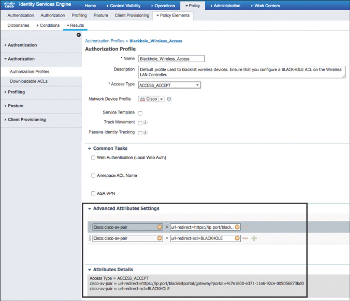
This attribute implementation supports the inclusion of many nested AV pairs by using the following format:
Relevant to wireless, these are the AVPs that we can embed: url-redirect-acl: Assists with triggering the redirect of the user and allowing access to the server hosting redirect page. url-redirect: Specifies the URL to where the user will be redirected. mDNS-profile-name: Overrides for the user the mDNS profile associated to the WLAN. avc-profile-name: Overrides for the user the AVC profile associated to the WLAN. role: Overrides/assigns the local policy (role) for the user. |
Figure 5-41 shows how we can leverage the attributes listed previously to configure authorization profiles that will send this value to the requesting NAS device. In this example the authorization profile will send back a URL to redirect the user and an ALC to trigger the redirect and limit the access that the user will be given.
802.1X
Unarguably, 802.1X is the preferred method for securing wireless network access, with PEAP and EAP-TLS being the EAP methods more widely deployed. Most large organizations will also tend to use Active Directory as the back-end identity repository where employee accounts reside.
The steps required to implement this scenario on the WLC are fairly simple. In addition to the common configuration previously discussed, a new WLAN needs to be created with the following parameters that are also shown in Figure 5-42:
Layer 2 Security should be set to WPA2 with AES Encryption and using 802.1X for authentication key management. Optionally, FT 802.1X can be enabled if implementing 802.11r.
AAA Servers can optionally be configured if you want to override the order of the global RADIUS servers list.
For the Advanced settings, it is recommended to enable AAA Override to allow ISE to send attribute-value pairs to dynamically override any existing client policy that was statically assigned via the WLAN configuration. Additionally, NAC state should be configured as ISE NAC to allow ISE to send CoA requests.

Figure 5-42 802.1X WLAN Settings
From a Cisco ISE perspective, we’ll start from the assumption that both the certificate configuration and the integration to AD already exist and was completed following the steps from the previous sections. The next step is to configure the authentication policy for 802.1X; one option on how to do it is shown in Figure 5-43.
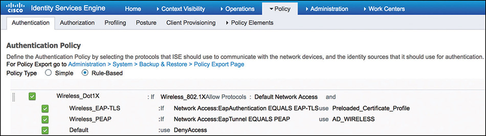
The authentication rule is configured with the Wireless_802.1X compound condition that is predefined in the library. This condition matches on wireless 802.1X-based authentication requests from the WLC by evaluating the AVPs using these expressions:
Radius:Service-Type Equals Framed (2)
Radius:NAS-Port-Type Equals Wireless—IEEE 802.11 (19)
In Example 5-2, we can see from the debug output on the WLC that the authentication request being sent for an 802.1X client includes AVPs (12 and 14 in this case) with values that match the Wireless_802.1X compound condition in ISE.
Example 5-2 debug aaa events enable—802.1X Authentication Request
*aaaQueueReader: Aug 24 22:42:32.259: AuthenticationRequest: 0xffebe69ce8
*aaaQueueReader: Aug 24 22:42:32.259:
  Callback.....................................0x1079c450
*aaaQueueReader: Aug 24 22:42:32.259:
  protocolType.................................0x00140001
*aaaQueueReader: Aug 24 22:42:32.259:
  proxyState...................................68:7F:74:FC:8C:0F-02:00
*aaaQueueReader: Aug 24 22:42:32.259:   Packet contains 19 AVPs:
*aaaQueueReader: Aug 24 22:42:32.259:       AVP[01] User-
  [email protected] (20 bytes)
*aaaQueueReader: Aug 24 22:42:32.259:       AVP[02] Chargeable-User-
  Identity.................0x64 (100) 'd' (1 byte)
*aaaQueueReader: Aug 24 22:42:32.259:       AVP[03] Location-
  Capable.........................0x00000001 (1) (4 bytes)
*aaaQueueReader: Aug 24 22:42:32.259:       AVP[05] Called-Station-
  Id........................cc-16-7e-5f-ca-10:8021Xssid (27 bytes)
*aaaQueueReader: Aug 24 22:42:32.259:       AVP[06] Nas-
  Port.................................0x00000001 (1) (4 bytes)
*aaaQueueReader: Aug 24 22:42:32.259:       AVP[07] Cisco / Audit-Session-
  Id.................647f640a000000195b80d028 (24 bytes)
*aaaQueueReader: Aug 24 22:42:32.259:       AVP[08] Acct-Session-
  Id..........................5b80d028/68:7f:74:fc:8c:0f/1402 (31 bytes)
*aaaQueueReader: Aug 24 22:42:32.259:       AVP[09] Nas-Ip-
  Address...........................0x647f640a (1686070282) (4 bytes)
*aaaQueueReader: Aug 24 22:42:32.259:       AVP[10] NAS-
  Identifier...........................0x574c4331 (1464615729) (4 bytes)
*aaaQueueReader: Aug 24 22:42:32.259:       AVP[11] Airespace / WLAN-
  Identifier..............0x00000001 (1) (4 bytes)
*aaaQueueReader: Aug 24 22:42:32.259:       AVP[12] Service-
  Type.............................0x00000002 (2) (4 bytes)
*aaaQueueReader: Aug 24 22:42:32.259:       AVP[13] Framed-
  MTU...............................0x00000514 (1300) (4 bytes)
*aaaQueueReader: Aug 24 22:42:32.259:       AVP[14] Nas-Port-
  Type............................0x00000013 (19) (4 bytes)
*aaaQueueReader: Aug 24 22:42:32.259:       AVP[15] Tunnel-
  Type..............................0x0000000d (13) (4 bytes)
*aaaQueueReader: Aug 24 22:42:32.259:       AVP[16] Tunnel-Medium-
  Type.......................0x00000006 (6) (4 bytes)
*aaaQueueReader: Aug 24 22:42:32.259:       AVP[17] Tunnel-Group-
  Id..........................100 (3 bytes)
*aaaQueueReader: Aug 24 22:42:32.259:       AVP[18] EAP-
  Message..............................DATA (25 bytes)
*aaaQueueReader: Aug 24 22:42:32.259:       AVP[19] Message-
  Authenticator....................DATA (16 bytes)
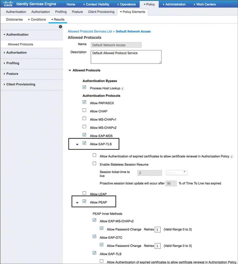
If the conditions are satisfied for this rule, the Default Network Access (preconfigured) allowed protocols services list shown in Figure 5-44 will be used. This list includes EAP-TLS and PEAP by default and could be modified (or another protocol service list can be created and used) to allow only the protocols that are needed.
The next step is to move to the identity rules, which define the identity source to be used by each rule. It is possible to leverage the Default identity rule and use an identity source sequence that encompasses the required sources for different protocols, but to show how it can be leveraged, we will use a separate rule for EAP-TLS and PEAP.
EAP-TLS will make use of the Preloaded_Certificate_Profile (preconfigured) that is shown in Figure 5-45. The certificate authentication profiles, among other things, can be used to determine which attribute in the certificate will be used as the identity of the user or device because there is no specific username field, and there are various fields on the certificate that could serve as the username.
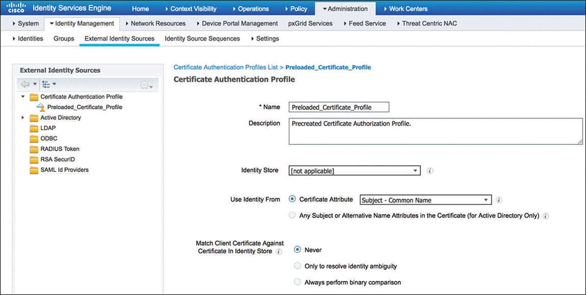
Figure 5-45 Certificate Authentication Profile PEAP, on the other hand, will use Active Directory (join point named AD_WIRELESS) to validate the credentials.
After we conclude the authentication process, ISE will move to evaluating the authorization policy. In the example represented in Figure 5-46, we have two authorization rules to show how to provide different network access to users.
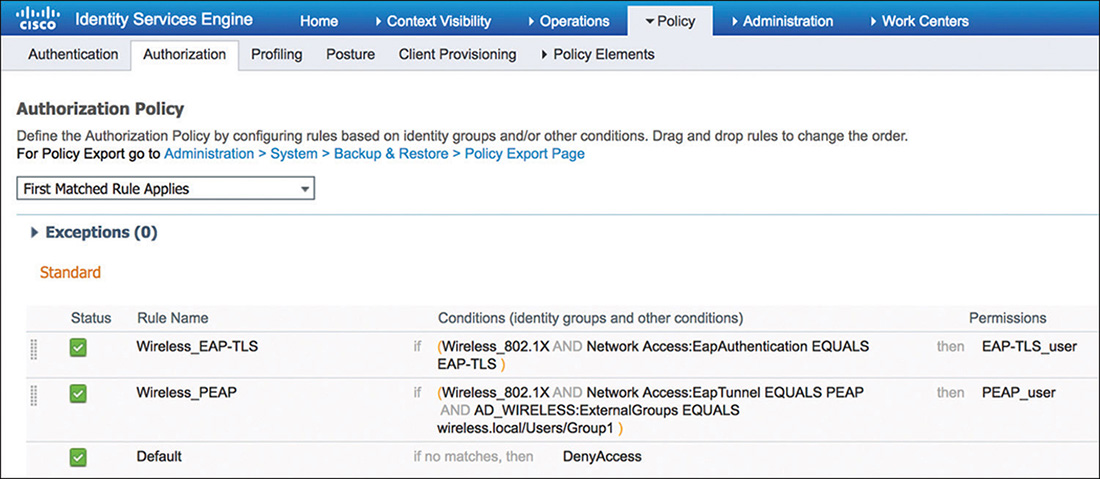
The first rule looks for wireless users (leveraging the Wireless_802.1X previously described) using EAP-TLS. This is a typical use case for internal users that have been provisioned with a valid certificate (such as employees). If meeting the criteria of the conditions for this rule, ISE will assign the EAP-TLS_user authorization profile that is shown in Figure 5-47 and that is configured to override the VLAN assigned by the WLC to the user.
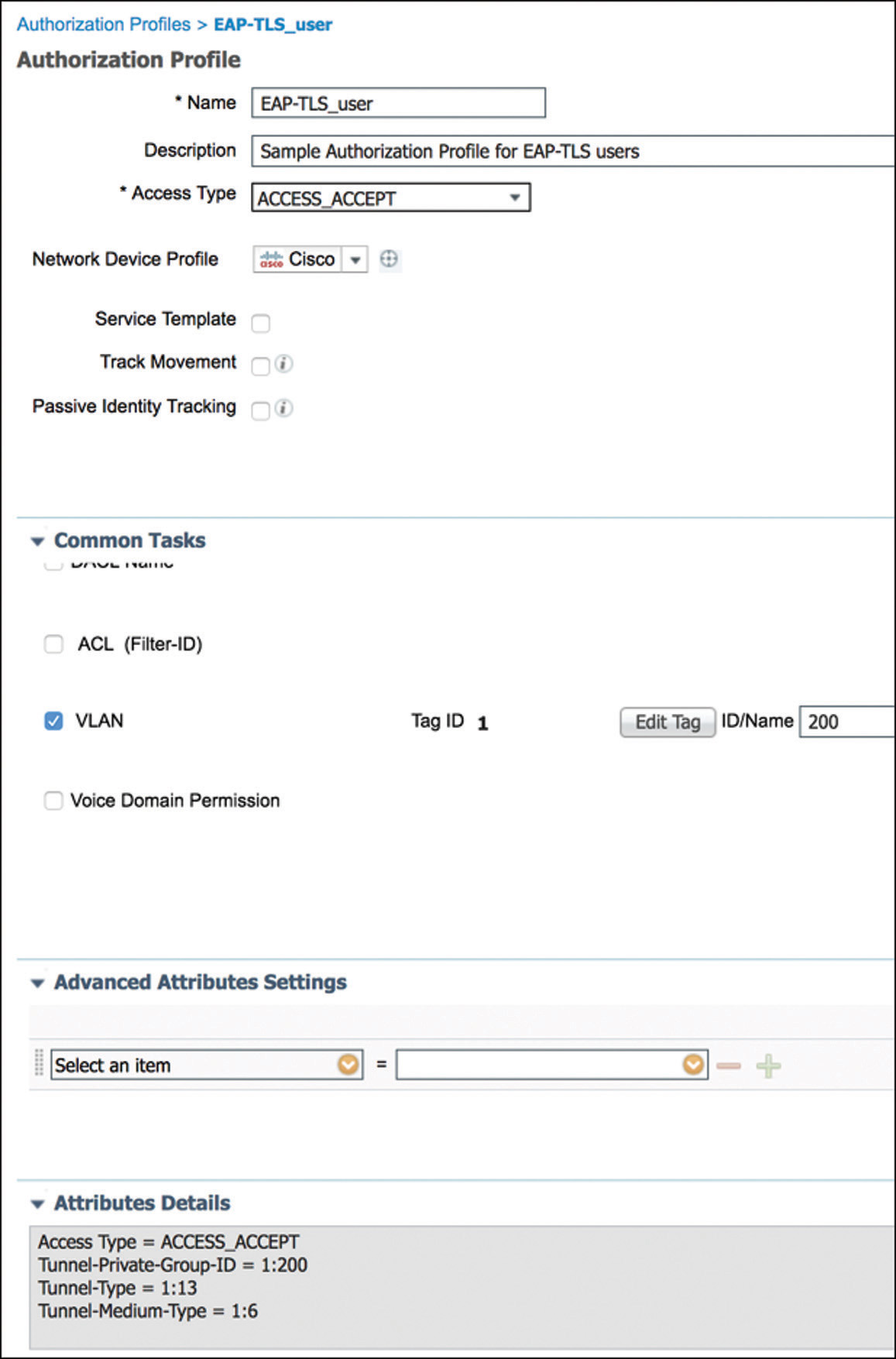
Figure 5-47 802.1X Authorization Profile – EAP-TLS Users As we look in Example 5-3, the Access-Accept received by the WLC, we can see the attributes that match those defined as part of the authorization profile.
Example 5-3 debug aaa events enable—Authorization Response EAP-TLS User
*radiusTransportThread: Aug 24 22:42:32.823: 68:7f:74:fc:8c:0f Access-Accept
  received from RADIUS server 192.168.100.6 (qid:15) with port:1812, pktId:60
*radiusTransportThread: Aug 24 22:42:32.823: AuthorizationResponse: 0x169505b0
*radiusTransportThread: Aug 24 22:42:32.823:
  structureSize................................554
*radiusTransportThread: Aug 24 22:42:32.823:
  resultCode...................................0
*radiusTransportThread: Aug 24 22:42:32.823:
  protocolUsed.................................0x00000001
*radiusTransportThread: Aug 24 22:42:32.823:
  proxyState...................................68:7F:74:FC:8C:0F-02:05
*radiusTransportThread: Aug 24 22:42:32.823:    Packet contains 10 AVPs:
*radiusTransportThread: Aug 24 22:42:32.823:        AVP[01] User-
  Name................................user1 (5 bytes)
*radiusTransportThread: Aug 24 22:42:32.823:        AVP[02]
  State..........................ReauthSession:647f640a000000195b80d028 (38 bytes)
*radiusTransportThread: Aug 24 22:42:32.823:        AVP[03]
  Class....................................CACS:647f640a000000195b80d028:
  ise/323248099/313 (47 bytes)
*radiusTransportThread: Aug 24 22:42:32.823:        AVP[04] Tunnel-
  Type..............................0x0100000d (16777229) (4 bytes)
*radiusTransportThread: Aug 24 22:42:32.823:        AVP[05] Tunnel-Medium-
  Type.......................0x01000006 (16777222) (4 bytes)
*radiusTransportThread: Aug 24 22:42:32.823:        AVP[06] EAP-
  Message..............................0x03820004 (58851332) (4 bytes)
*radiusTransportThread: Aug 24 22:42:32.823:        AVP[07] Message-
  Authenticator....................DATA (16 bytes)
*radiusTransportThread: Aug 24 22:42:32.823:        AVP[08] Tunnel-Group-
  Id..........................0x01323030 (20066352) (4 bytes)
*radiusTransportThread: Aug 24 22:42:32.823:        AVP[09] Microsoft / MPPE-
  Send-Key................DATA (32 bytes)
*radiusTransportThread: Aug 24 22:42:32.823:        AVP[10] Microsoft / MPPE-
  Recv-Key................DATA (32 bytes)
The second rule not only looks for wireless users using PEAP but also checks whether they belong to the right Active Directory user group. This use case is common in certain BYOD scenarios or when giving access to contractors or other users that have valid AD accounts. Matching this rule will assign the PEAP_user authorization profile as shown in Figure 5-48, for which ISE will send back the ACL name that the WLC will need to apply to the user session.
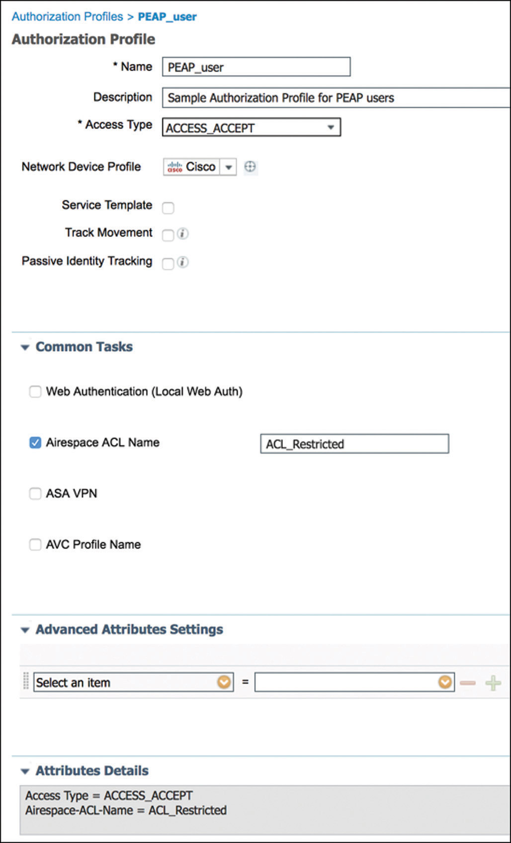
Figure 5-48 802.1X Authorization Profile—PEAP Users Now from the WLC perspective, we have Example 5-4 that shows the Access-Accept containing the ACL name as part of one of the AVPs received from ISE.
Example 5-4 debug aaa events enable—Authorization Response PEAP User
*radiusTransportThread: Aug 24 23:39:01.550: 68:7f:74:fc:8c:0f Access-Accept received
  from RADIUS server 192.168.100.6 (qid:15) with port:1812, pktId:72
*radiusTransportThread: Aug 24 23:39:01.550: AuthorizationResponse: 0x169505b0
*radiusTransportThread: Aug 24 23:39:01.550:    structure-
  Size................................508
*radiusTransportThread: Aug 24 23:39:01.550:    result-
  Code...................................0
*radiusTransportThread: Aug 24 23:39:01.550:
  protocolUsed.................................0x00000001
*radiusTransportThread: Aug 24 23:39:01.550:
  proxyState...................................68:7F:74:FC:8C:0F-02:05
*radiusTransportThread: Aug 24 23:39:01.550:    Packet contains 8 AVPs:
*radiusTransportThread: Aug 24 23:39:01.550:        AVP[01] User-
  Name................................user1 (5 bytes)
*radiusTransportThread: Aug 24 23:39:01.550:        AVP[02]
  State.............................ReauthSession:647f640a0000001a5b80dd65
  (38 bytes)
*radiusTransportThread: Aug 24 23:39:01.550:        AVP[03]
  Class....................................CACS:647f640a0000001a5b80dd65:
  ise/323248099/318 (47 bytes)
*radiusTransportThread: Aug 24 23:39:01.550:        AVP[04] EAP-
  Message..............................0x03260004 (52822020) (4 bytes)
*radiusTransportThread: Aug 24 23:39:01.550:        AVP[05] Message-
  Authenticator....................DATA (16 bytes)
*radiusTransportThread: Aug 24 23:39:01.550:        AVP[06] Microsoft / MPPE-
  Send-Key................DATA (32 bytes)
*radiusTransportThread: Aug 24 23:39:01.550:        AVP[07] Microsoft / MPPE-
  Recv-Key................DATA (32 bytes)
*radiusTransportThread: Aug 24 23:39:01.550:        AVP[08] Airespace / ACL-
  Name.....................ACL_Restricted (14 bytes)
MAC Filtering and MAC Authentication Bypass (MAB)
MAC Filtering, and its variation MAC Authentication Bypass, would typically be configured on an open or PSK WLAN and allows the use of the MAC address of an endpoint to determine what type of network access to provide, depending on whether it is a known or unknown device.
Configuration on the WLC requires creating a WLAN with the following settings that are also represented in Figure 5-49:
Layer 2 Security can either be none (open) or using WPA2 with AES Encryption and PSK for authentication key management. MAC filtering needs to be enabled.
AAA Servers and Advanced settings should be configured following the same guidelines mentioned on the 802.1X configuration section.
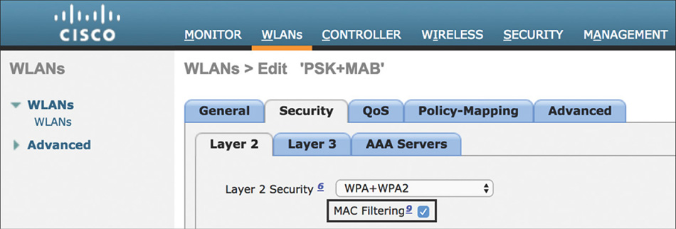
Figure 5-49 MAB WLAN Settings
The Authentication Policy on ISE would need to have a rule configured, such as the one shown in Figure 5-50.
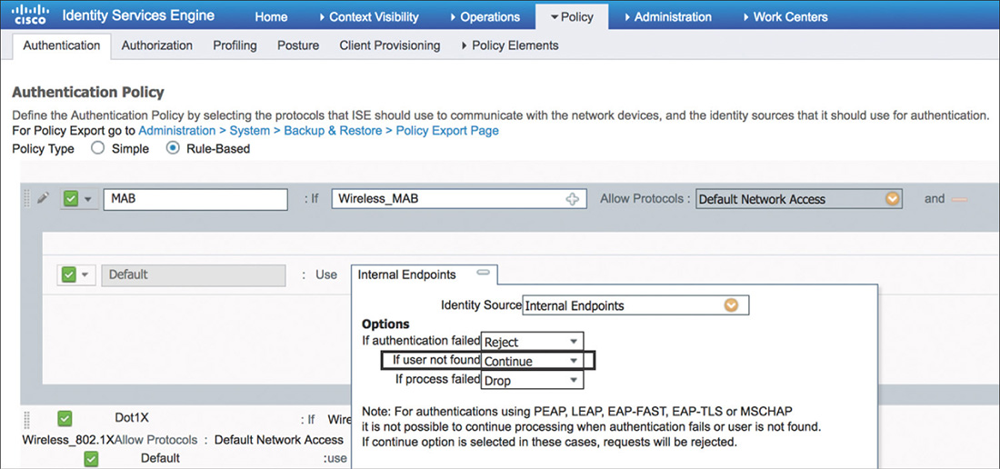
This rule for MAB will make use of the Wireless_MAB compound condition from the library. This condition matches on MAC authentication requests from the WLC by using the following expressions:
Radius:Service-Type Equals Call Check (10)
Radius:NAS-Port-Type Equals Wireless—IEEE 802.11 (19)
Example 5-5 shows the debug output from the WLC where we can see the AVPs (9 and 11 in this example) that will be sent as part of the MAC authentication request and that will match in the configured condition in ISE.
Example 5-5 debug aaa events enable—MAC Authentication Request
*aaaQueueReader: Aug 28 21:10:13.342: AuthenticationRequest: 0xffebe7b250
*aaaQueueReader: Aug 28 21:10:13.342:
  Callback.....................................0x105d6df0
*aaaQueueReader: Aug 28 21:10:13.342:
  protocolType.................................0x40000001
*aaaQueueReader: Aug 28 21:10:13.342:
  proxyState...................................68:7F:74:FC:8C:0F-00:00
*aaaQueueReader: Aug 28 21:10:13.342:   Packet contains 16 AVPs:
*aaaQueueReader: Aug 28 21:10:13.342:       AVP[01] User-
  Name................................687f74fc8c0f (12 bytes)
*aaaQueueReader: Aug 28 21:10:13.342:       AVP[02] Called-Station-
  Id........................cc-16-7e-30-6b-50:MACauthssid (29 bytes)
*aaaQueueReader: Aug 28 21:10:13.342:       AVP[03] Calling-Station-
  Id.......................68-7f-74-fc-8c-0f (17 bytes)
*aaaQueueReader: Aug 28 21:10:13.342:       AVP[04] Nas-
  Port.................................0x00000001 (1) (4 bytes)
*aaaQueueReader: Aug 28 21:10:13.342:       AVP[05] Nas-Ip-
  Address...........................0x647f640a (1686070282) (4 bytes)
*aaaQueueReader: Aug 28 21:10:13.342:       AVP[06] NAS-
  Identifier...........................0x574c4331 (1464615729) (4 bytes)
*aaaQueueReader: Aug 28 21:10:13.342:       AVP[07] Airespace / WLAN-
  Identifier..............0x00000002 (2) (4 bytes)
*aaaQueueReader: Aug 28 21:10:13.342:       AVP[08] User-
  Password............................[...]
*aaaQueueReader: Aug 28 21:10:13.342:       AVP[09] Service-
  Type.............................0x0000000a (10) (4 bytes)
*aaaQueueReader: Aug 28 21:10:13.342:       AVP[10] Framed-
  MTU...............................0x00000514 (1300) (4 bytes)
*aaaQueueReader: Aug 28 21:10:13.342:       AVP[11] Nas-Port-
  Type............................0x00000013 (19) (4 bytes)
*aaaQueueReader: Aug 28 21:10:13.342:       AVP[12] Tunnel-
  Type..............................0x0000000d (13) (4 bytes)
*aaaQueueReader: Aug 28 21:10:13.342:       AVP[13] Tunnel-Medium-
  Type.......................0x00000006 (6) (4 bytes)
*aaaQueueReader: Aug 28 21:10:13.342:       AVP[14] Tunnel-Group-
  Id..........................100 (3 bytes)
*aaaQueueReader: Aug 28 21:10:13.342:       AVP[15] Cisco / Audit-Session-
  Id.................647f640a000000265b860085 (24 bytes)
*aaaQueueReader: Aug 28 21:10:13.342:       AVP[16] Acct-Session-
  Id..........................5b860085/68:7f:74:fc:8c:0f/1642 (31 bytes)
A critical part of the configuration for MAB is to change the If User Not Found option to Continue. This will allow ISE to complete the authentication host lookup process moving to the authorization policy even if dealing with an unknown device.
After moving the Authorization Policy, there are multiple ways to provide differentiated network access to a known versus unknown device. Figure 5-51 shows one possible way it can be implemented and how it can be implemented.
The first and more specific rule looks for wireless MAC authentication requests where the endpoints belong to the RegisteredDevices identity group, and it permits access to those devices.
The second rule is left generic enough to act as a catch-all rule for MAB, and it looks only for wireless MAC authentication requests. In this scenario, the rule will assign RestrictedAccess to unknown devices, which, for example, could be used to apply an ACL or VLAN while the device gets registered or profiled.
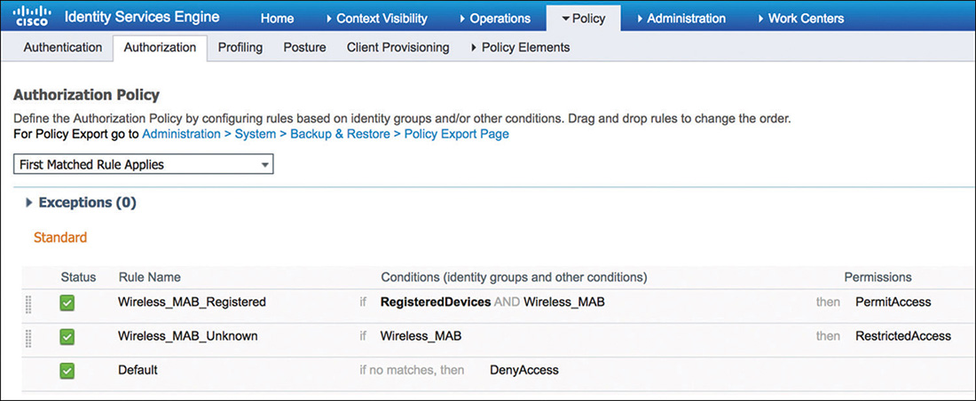
Figure 5-51 MAB Authorization Policy
Local Web Authentication
Web authentication (WebAuth) is a Layer 3 security mechanism that allows users, typically guests, to easily gain access to the network by providing credentials through a web browser.
Two deployment modes are available for WebAuth with ISE: Local Web Authentication (LWA) and Central Web Authentication (CWA). Although Cisco recommends the use of CWA with ISE, there are some scenarios where LWA is preferred due to its simplicity or because it is the only viable option for the network environment.
In LWA, the WLC is “locally” configured to redirect the user to the web authentication portal and will be responsible for receiving the user credentials that need to be submitted to ISE for authentication.
When a user connects to a WLAN configured for LWA, it will go through the flow shown in Figure 5-52.
The user will connect to an open (although less common, PSK security is also supported) SSID that is configured for WebAuth.
The WLC will apply and enforce an access control list that will typically allow access only to DHCP and DNS, and access to the authentication web portal.
After the client acquires an IP address, the controller will move the user to WebAuth_reqd state.
The user will open a browser trying to fetch a web page and the WLC will intercept the HTTP request (HTTPS is not intercepted by default) and redirect the user to either an internal WebAuth page or to ISE.
The user is presented with the guest login page where he or she will enter the username and password. The login page will take the user credentials input and submit them to the WLC. (It is the client browser that submits the credentials to the WLC, not the external portal if there is one.)
The WLC uses RADIUS to authenticate the username and password against ISE.
ISE authenticates and authorizes the user.
If the credentials are valid, ISE will notify the WLC to change to a new access policy to allow the user access to the network. The client then moves to RUN state with either full access or possibly with a post-authentication ACL applied if ISE returned an Airespace-ACL RADIUS attribute.
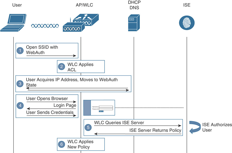
Figure 5-52 Local Web Authentication
Configuration of LWA on the WLC will typically start by defining the preauthentication ACL as the one shown in Figure 5-53. This ACL will be used to provide limited network access and trigger the redirection process. Here are a couple of consideration to keep in mind regarding the ACL:
If you’re using the internal WebAuth portal, it is not required to define an ACL unless there is some specific traffic that needs to be allowed before the user authenticates.
The ACL needs to permit traffic to where the WebAuth portal is hosted, in this example ISE.
If deploying FlexConnect, a FlexConnect ACL will need to be configured instead of a regular controller ACL.
By default, DHCP and DNS are allowed by the preauthentication ACL. If configuring an explicit deny statement in the ACL, you need to make sure that you have a rule that allows DNS traffic, or else it will get blocked.
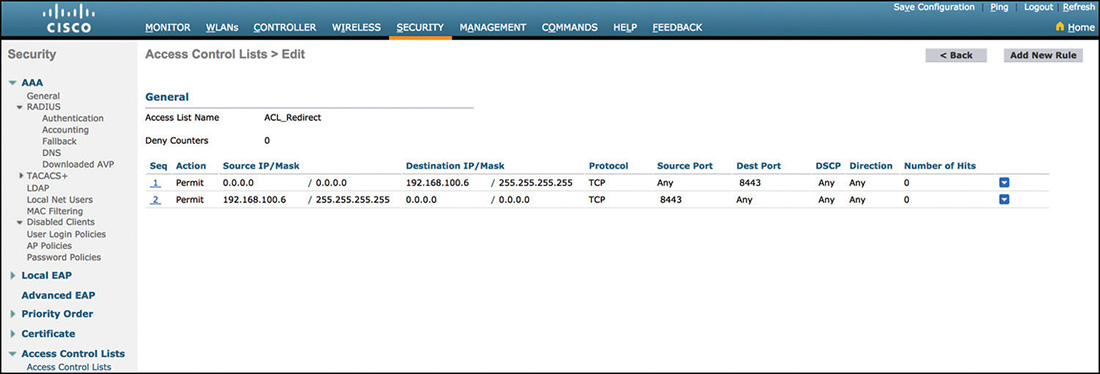
Figure 5-53 LWA Redirect ACL
As it relates to the WLAN, the following settings need to be configured:
Layer 2 Security will typically be none (open) to provide a simpler user experience; however, if needed, it can be implemented with PSK as well.
The Layer 3 Security policy will need to be configured for web authentication, as shown in Figure 5-54. The preauthentication ACL previously created will need to be added to allow access to the WebAuth portal (this is not required if using the WLC internal portal).
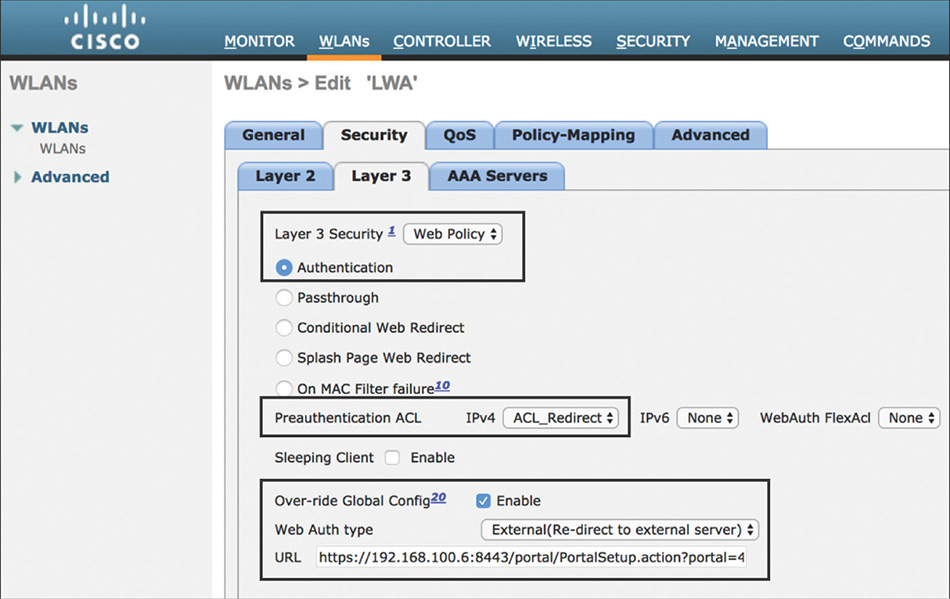
Figure 5-54 LWA Layer 3 WLAN Settings Finally, if using an external portal, the URL to redirect the user will need to be specified (can be also configured globally). To find out the correct URL for the portal in ISE, navigate to Work Centers > Guest Access > Portal and Components > Guest Portals Configure and select the specific portal that will be used. From there you can right-click the link Portal Test URL, as shown in Figure 5-55, and choose Copy Link Location.
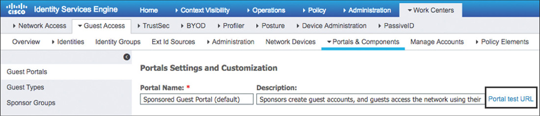
Figure 5-55 ISE LWA Portal URL Note
One variation of this configuration is to configure MAC Filtering for Layer 2 Security and On MAC Filter Failure for Layer 3. This can be useful in bypassing the web authentication portal if the device has already been learned/registered on ISE for scenarios such as when dealing with headless devices (such as printers or other devices with limited capabilities).
The rest of the settings will be configured in accordance with the recommendations mentioned previously for integrating with ISE.
After completing the configuration on the WLC, we can now move to ISE and configure the authentication rule shown in Figure 5-56 to support LWA.
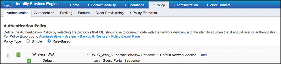
This rule is configured to use the WLC_Web_Authentication compound condition from the library. This condition matches on web authentication requests from the WLC by using these expressions:
Radius:Service-Type Equals Login (1)
Radius:NAS-Port-Type Equals Wireless—IEEE 802.11 (19)
Looking at the output from the WLC in Example 5-6, we can see the AVPs (3 and 10 for this scenario) that accompany the access request sent after the user submits its credentials for validation via ISE.
Example 5-6 debug aaa events enable—LWA Authentication Request
*aaaQueueReader: Aug 28 23:46:53.144: AuthenticationRequest: 0xffebffc418
*aaaQueueReader: Aug 28 23:46:53.144:
Callback.....................................0x11904570
*aaaQueueReader: Aug 28 23:46:53.144:
protocolType.................................0x00000001
*aaaQueueReader: Aug 28 23:46:53.144:
proxyState...................................68:7F:74:FC:8C:0F-00:00
*aaaQueueReader: Aug 28 23:46:53.144:   Packet contains 14 AVPs:
*aaaQueueReader: Aug 28 23:46:53.144:       AVP[01] User-
  Name................................guestuser (9 bytes)
*aaaQueueReader: Aug 28 23:46:53.144:       AVP[02] User-
  Password............................[...]
*aaaQueueReader: Aug 28 23:46:53.144:       AVP[03] Service-
  Type.............................0x00000001 (1) (4 bytes)
*aaaQueueReader: Aug 28 23:46:53.144:       AVP[04] Nas-Ip-
  Address...........................0x647f640a (1686070282) (4 bytes)
*aaaQueueReader: Aug 28 23:46:53.144:       AVP[05] Nas-
  Port.................................0x00000001 (1) (4 bytes)
*aaaQueueReader: Aug 28 23:46:53.144:       AVP[06] Cisco / Audit-Session-
  Id.................647f640a0000002a5b8624b5 (24 bytes)
*aaaQueueReader: Aug 28 23:46:53.144:       AVP[07] Framed-IP-
  Address........................0x647f640d (1686070285) (4 bytes)
*aaaQueueReader: Aug 28 23:46:53.144:       AVP[08] Acct-Session-
  Id..........................5b8624b5/68:7f:74:fc:8c:0f/1654 (31 bytes)
*aaaQueueReader: Aug 28 23:46:53.144:       AVP[09] NAS-
  Identifier...........................0x574c4331 (1464615729) (4 bytes)
*aaaQueueReader: Aug 28 23:46:53.144:       AVP[10] Nas-Port-
  Type............................0x00000013 (19) (4 bytes)
*aaaQueueReader: Aug 28 23:46:53.144:       AVP[11] Airespace / WLAN-
  Identifier..............0x00000003 (3) (4 bytes)
*aaaQueueReader: Aug 28 23:46:53.144:       AVP[12] Calling-Station-
  Id.......................68-7f-74-fc-8c-0f (17 bytes)
*aaaQueueReader: Aug 28 23:46:53.144:       AVP[13] Called-Station-
  Id........................f4-0f-1b-36-13-a0:LWAssid (25 bytes)
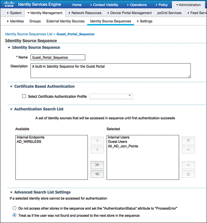
For this example, we have selected the preconfigured Guest_Portal_Sequence identity source sequence, which can be customized, but by default, it will allow all internal, guest, and AD users to log in, as displayed in Figure 5-57.
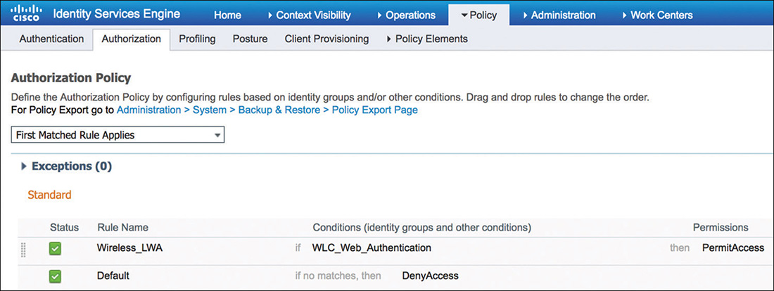
Finally, because LWA is used typically to provide basic guest services, its associated authorization policy will be fairly simple, as illustrated in Figure 5-58. The rule conditions will match for web authentication requests and will send back an access-accept to signal the WLC to allow access to authenticated users.
Central Web Authentication
Guest services using Central Web Authentication (CWA) would be the preferred deployment model due to the flexibility it provides. It builds on top of MAB, and it can provide additional capabilities that go beyond guest network access.
In CWA, the configuration for redirecting the user, the web authentication portal and the responsibility of directly processing the user credentials, resides “centrally” in ISE. When a user connects to a CWA-enabled network, it will go through the flow shown in Figure 5-59.
The user will connect to an open SSID. Transparent to the user, the WLAN is configured to perform MAC authentication.
The WLC handles the MAC authentication process and sends the request to ISE.
ISE is configured to perform MAB and will send back to the WLC the redirection attributes.
The user acquires an IP address and will open a browser trying to fetch a web page (on modern operating systems, a pop-up might even show up when the system detected the portal page automatically by sending HTTP test probes). At this point the WLC will intercept the HTTP request and redirect the user to the WebAuth page that resides on ISE.
The user is presented with the guest login page where it will enter the username and password. These credentials get submitted directly to ISE through the portal.
ISE will authenticate the user, and if successful, it will send a CoA back to the WLC.
When the user reconnects, the WLC will start the MAC authentication process all over again, but this time ISE is aware that the user has authenticated, and it will grant it access to the network, possibly returning specific authorization attributes such as an ACL.
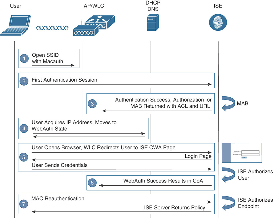
Figure 5-59 Central Web Authentication
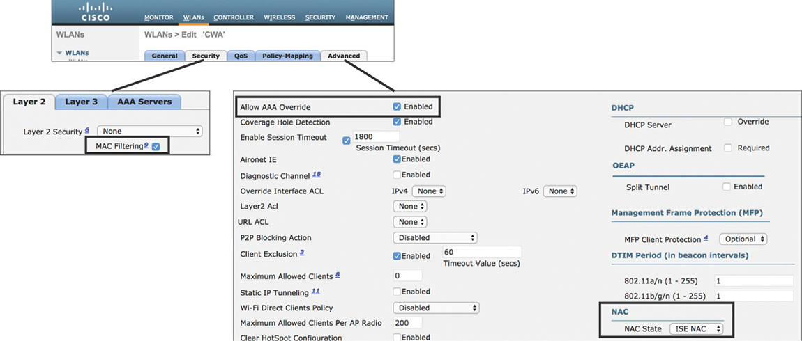
Because this flow builds on top of MAB, the WLAN configuration on the WLC will be the same as previously reviewed in the MAB section. In this scenario, however, make sure that AAA Override and ISE NAC are enabled as shown in Figure 5-60.
Although not statically applied to the WLAN as in LWA, the WLC needs to have an ACL configured similar to the one shown in Figure 5-61 that will be used to redirect the traffic. This ACL must comply with the following requirements:
The ACL needs to permit traffic to ISE on the port configured for the web portal (default 8443).
If deploying FlexConnect, a FlexConnect ACL will need to be configured instead of a regular controller ACL. This is configured as a Policy ACL on the AP or at the FlexConnect group level (it must be provisioned on the AP beforehand).
As previously mentioned, by default, DHCP and DNS are allowed on an ACL. If configuring an explicit deny statement in the ACL, make sure that you add the required rules to permit DNS traffic.
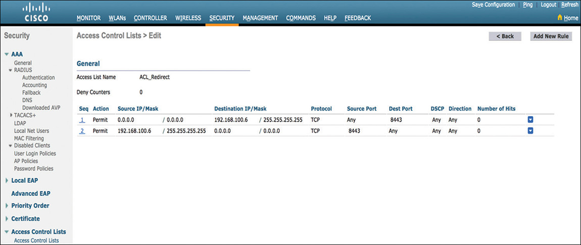
Figure 5-61 CWA Redirect ACL
On ISE, the Authentication Policy will leverage the MAB rule previously discussed. It is worth highlighting again the importance of making sure that the If User Not Found option for the identity source is changed to Continue, as shown in Figure 5-62. Users just initiating the CWA flow will not be known by ISE, but they will still need to move to the authorization policy to get the redirect URL and ACL applied to their session.

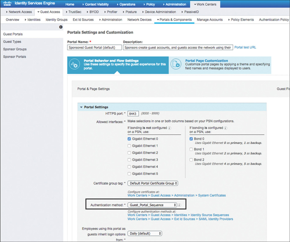
One important thing to note is that the Authentication Policy doesn’t require a rule to process the credentials provided via the portal. The reason for this is that the CWA username and password validation is handled separately, and the identity source that is to be used is configured directly under the portal settings, as shown in Figure 5-63.
Because CWA is a multistep process, the Authorization Policy will include the two rules that can be seen in Figure 5-64.
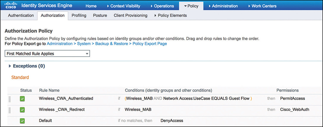
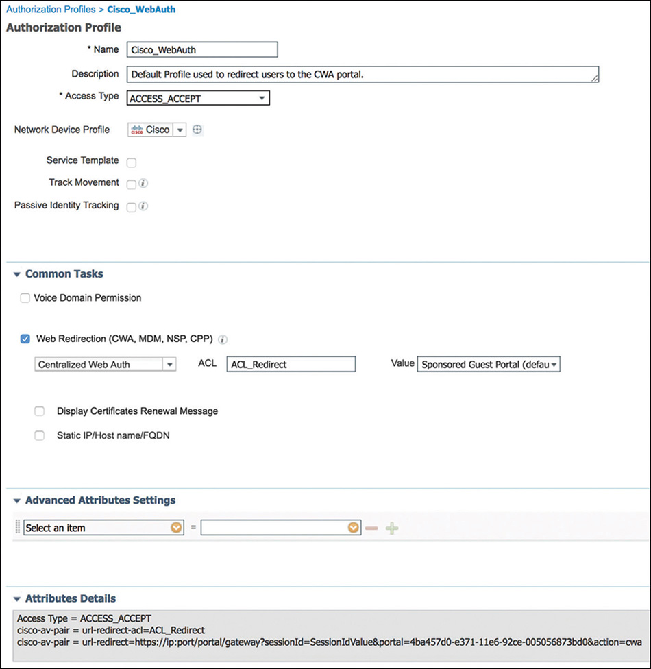
The first rule that will be used in the CWA flow (a more generic rule thus listed at a lower position in the policy) just looks for the first MAC authentication request in the CWA request. As part of the Authorization Profile that is shown in Figure 5-65 and that is mapped to this rule, ISE will send the redirect attributes (URL and redirect ACL) that will be enforced by the WLC.
Example 5-7 shows the output of the WLC debug showing how the URL and ACL are being received via AVPs as part of the authorization response. One thing to notice is that the PSN node that processed the request will use its FQDN to craft the URL to redirect the user.
Example 5-7 debug aaa events enable—CWA Authorization Response
*radiusTransportThread: Aug 29 17:35:00.432: 68:7f:74:fc:8c:0f Access-Accept
  received from RADIUS server 192.168.100.6 (qid:15) with port:1812, pktId:188
*radiusTransportThread: Aug 29 17:35:00.432: AuthorizationResponse: 0x169505b0
*radiusTransportThread: Aug 29 17:35:00.432:    structureSize...................564
*radiusTransportThread: Aug 29 17:35:00.432:    resultCode........................0
*radiusTransportThread: Aug 29 17:35:00.432:
  protocolUsed.................................0x00000001
*radiusTransportThread: Aug 29 17:35:00.432:
  proxyState...................................68:7F:74:FC:8C:0F-00:00
*radiusTransportThread: Aug 29 17:35:00.432:    Packet contains 5 AVPs:
*radiusTransportThread: Aug 29 17:35:00.432:        AVP[01] User-
  Name................................68-7F-74-FC-8C-0F (17 bytes)
*radiusTransportThread: Aug 29 17:35:00.432:        AVP[02]
  State............................ReauthSession:647f640a0000006d5b871f94 (38 bytes)
*radiusTransportThread: Aug 29 17:35:00.432:        AVP[03] Class...................
  .................CACS:647f640a0000006d5b871f94:ise/323248099/1400 (48 bytes)
*radiusTransportThread: Aug 29 17:35:00.432:        AVP[04] Cisco / Url-Redirect-
  Acl.................ACL_Restricted (14 bytes)
*radiusTransportThread: Aug 29 17:35:00.432:        AVP[05] Cisco / Url-
  Redirect.....................DATA (175 bytes)
*radiusTransportThread: Aug 29 17:35:00.432: 68:7f:74:fc:8c:0f processing avps[0]:
  attribute 1
*radiusTransportThread: Aug 29 17:35:00.432: 68:7f:74:fc:8c:0f username = 68-7F-74-
  FC-8C-0F
*radiusTransportThread: Aug 29 17:35:00.432: 68:7f:74:fc:8c:0f processing avps[1]:
  attribute 24
*radiusTransportThread: Aug 29 17:35:00.432: 68:7f:74:fc:8c:0f processing avps[2]:
  attribute 25
*radiusTransportThread: Aug 29 17:35:00.432: 68:7f:74:fc:8c:0f processing avps[3]:
  attribute 6
*radiusTransportThread: Aug 29 17:35:00.432: 68:7f:74:fc:8c:0f processing avps[4]:
  attribute 5
*apfReceiveTask: Aug 29 17:35:00.432: 68:7f:74:fc:8c:0f Setting client ReasonCode
  from (0) to (126)
*apfReceiveTask: Aug 29 17:35:00.432: 68:7f:74:fc:8c:0f Received SGT for this Client.
*apfReceiveTask: Aug 29 17:35:00.432: 68:7f:74:fc:8c:0f SGT is not applied, sgtLen 0,
  sgt_stringp 0xffebe6198b
*apfReceiveTask: Aug 29 17:35:00.432: 68:7f:74:fc:8c:0f AAA Override Url-Redirect
  'https://ise.wireless.local:8443/portal/gateway?sessionId=647f640a0000006d5b871f94
  &portal=4bd88730-e371-11e6-92ce-005056873bd0&action=cwa&token=
*apfReceiveTask: Aug 29 17:35:00.432: 68:7f:74:fc:8c:0f Redirect URL received for
  client from RADIUS. Client will be moved to WebAuth_Reqd state to facilitate
  redirection. Skip web-auth Flag = 0
*apfReceiveTask: Aug 29 17:35:00.432: 68:7f:74:fc:8c:0f Resetting web IPv4 acl from
  255 to 255
*apfReceiveTask: Aug 29 17:35:00.432: 68:7f:74:fc:8c:0f Resetting web IPv4 Flex acl
  from 65535 to 65535
*apfReceiveTask: Aug 29 17:35:00.432: 68:7f:74:fc:8c:0f AAA Override Url-Redirect-
  Acl 'ACL_Redirect' mapped to ACL ID 0 and Flexconnect ACL ID 65535
The more specific rule (listed at a higher position on the policy) will focus on the second authentication/authorization request. This rule condition will look for wireless MAC authentication requests that also contain the Guest Flow flag set in ISE to indicate that the user was previously authenticated via the portal. This rule is responsible for allowing network access to the guest user and can include additional attributes that can be sent as part of the access accept message to further customize the type of service that will be granted.
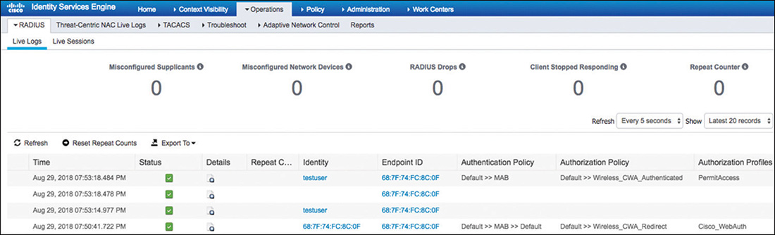
As noted before, a client going through the CWA flow will step through a series of authentication/authorization steps. In Figure 5-66 we can see in the live log from ISE how a user moves through this process. For this reason, being able to dynamically change the session authorization via CoA messages is critical.
After the user enters his or her credentials in the web portal, ISE will issue a CoA to the WLC to modify the previous state achieved after the first MAB process. The message received by the WLC from ISE can been seen in Example 5-8, and because it is an unsolicited request, it contains attributes to identify the client whose status needs to be changed.
Example 5-8 debug aaa events enable—CoA
*radiusCoASupportTransportThread: Aug 29 19:52:43.858: Received a 'CoA-Request' from
  192.168.100.6 port 62926
*radiusCoASupportTransportThread: Aug 29 19:52:43.858: Packet contains 9 AVPs:
*radiusCoASupportTransportThread: Aug 29 19:52:43.858:     AVP[01] Nas-Ip-Address..
  .........................0x647f640a (1686070282) (4 bytes)
*radiusCoASupportTransportThread: Aug 29 19:52:43.858:     AVP[02] Calling-Station-
  Id.......................68-7f-74-fc-8c-0f (17 bytes)
*radiusCoASupportTransportThread: Aug 29 19:52:43.858:     AVP[03] Acct-Event-
  Time..........................0x5b873ffe (1535590398) (4 bytes)
*radiusCoASupportTransportThread: Aug 29 19:52:43.858:     AVP[04] Message-
  Authenticator....................DATA (16 bytes)
*radiusCoASupportTransportThread: Aug 29 19:52:43.858:     AVP[05] Message-
  Authenticator....................DATA (16 bytes)
*radiusCoASupportTransportThread: Aug 29 19:52:43.858:     AVP[06] Unknown
  Attribute 0......................NULL (0 bytes)
*radiusCoASupportTransportThread: Aug 29 19:52:43.858:     AVP[07] Unknown
  Attribute 0......................NULL (0 bytes)
*radiusCoASupportTransportThread: Aug 29 19:52:43.858:     AVP[08] Unknown
  Attribute 0......................NULL (0 bytes)
*radiusCoASupportTransportThread: Aug 29 19:52:43.858:     AVP[09] Unknown
  Attribute 0......................NULL (0 bytes)
Profiling
The WLC is enabled with device profiler capabilities that allow it to collect client information that can be sent to ISE via RADIUS accounting messages. Based on this information, administrators can then apply a policy to the device after its type is known.
The WLC acts as the collector for two types of packets:
DHCP: The WLC receives a copy of the DHCP_REQUEST packet and parses the information to obtain the HostName (Option 12) and the Vendor Class Identifier (Option 60). This information is then conveyed to ISE via the cisco-av-pair: dhcp-option=<DHCP option> RADIUS Vendor Specific Attribute.
HTTP: The first HTTP packet sent from the client will be detected, and the WLC will use the user-agent attribute from the HTTP header. This information will then be sent to ISE via the cisco-av-pair: http-tlv=User-Agent=<user-agent> attribute.
To configure this feature, go to WLANs, click the target WLAN ID, go to the Advanced tab, and from there check both DHCP and HTTP profiling under the Radius Client Profiling section, as shown in Figure 5-67.
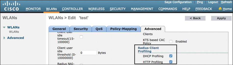
From Example 5-9, we can see the profiling information from an iPhone device being sent to ISE via an Accounting message.
Example 5-9 debug aaa events enable—Accounting Message
*aaaQueueReader: Jun 02 16:23:14.910: AccountingMessage Accounting Interim:
  0x2c869140
*aaaQueueReader: Jun 02 16:23:14.910: Packet contains 36 AVPs:
*aaaQueueReader: Jun 02 16:23:14.910:     AVP[01] User-
  [email protected] (18 bytes)
*aaaQueueReader: Jun 02 16:23:14.910:     AVP[02] Nas-
  Port.................................0x0000000d (13) (4 bytes)
*aaaQueueReader: Jun 02 16:23:14.910:     AVP[03] Nas-Ip-
  Address...........................0xac15220a (-1407901174) (4 bytes)
*aaaQueueReader: Jun 02 16:23:14.910:     AVP[04] Nas-Ipv6-
  Address.........................DATA (16 bytes)
*aaaQueueReader: Jun 02 16:23:14.910:     AVP[05] Framed-IP-
  Address........................0xac15211b (-1407901413) (4 bytes)
*aaaQueueReader: Jun 02 16:23:14.910:     AVP[06] Framed-IPv6-
  Prefix.......................DATA (18 bytes)
*aaaQueueReader: Jun 02 16:23:14.910:     AVP[07] Framed-IPv6-
  Prefix.......................DATA (18 bytes)
*aaaQueueReader: Jun 02 16:23:14.910:     AVP[08] Framed-IPv6-
  Prefix.......................DATA (18 bytes)
*aaaQueueReader: Jun 02 16:23:14.910:     AVP[09] Framed-IPv6-
  Prefix.......................DATA (18 bytes)
*aaaQueueReader: Jun 02 16:23:14.910:     AVP[10] Framed-IPv6-
  Prefix.......................DATA (18 bytes)
*aaaQueueReader: Jun 02 16:23:14.910:     AVP[11] Framed-IPv6-
  Prefix.......................DATA (18 bytes)
*aaaQueueReader: Jun 02 16:23:14.910:     AVP[12] Framed-IPv6-
  Prefix.......................DATA (18 bytes)
*aaaQueueReader: Jun 02 16:23:14.910:     AVP[13]
  Class....................................CACS:ac15220a00000e0b556da83b:
  ise01/222106059/91676 (51 bytes)
*aaaQueueReader: Jun 02 16:23:14.910:     AVP[14] NAS-
  Identifier...........................WLC1 (17 bytes)
*aaaQueueReader: Jun 02 16:23:14.910:     AVP[15] Airespace / WLAN-
  Identifier..............0x00000005 (5) (4 bytes)
*aaaQueueReader: Jun 02 16:23:14.910:     AVP[16] Acct-Session-
  Id..........................556da83e/54:e4:3a:6b:de:ad/3171 (31 bytes)
*aaaQueueReader: Jun 02 16:23:14.910:     AVP[17] Nas-Port-
  Type............................0x00000013 (19) (4 bytes)
*aaaQueueReader: Jun 02 16:23:14.910:     AVP[18] Cisco / Audit-Session-
  Id.................ac15220a00000e0b556da83b (24 bytes)
*aaaQueueReader: Jun 02 16:23:14.910:     AVP[19] Acct-
  Authentic...........................0x00000001 (1) (4 bytes)
*aaaQueueReader: Jun 02 16:23:14.910:     AVP[20] Tunnel-
  Type..............................0x0000000d (13) (4 bytes)
*aaaQueueReader: Jun 02 16:23:14.910:     AVP[21] Tunnel-Medium-
  Type.......................0x00000006 (6) (4 bytes)
*aaaQueueReader: Jun 02 16:23:14.910:     AVP[22] Tunnel-Group-
  Id..........................711 (3 bytes)
*aaaQueueReader: Jun 02 16:23:14.910:     AVP[23] Acct-Event-
  Time..........................0x556dbc52 (1433254994) (4 bytes)
*aaaQueueReader: Jun 02 16:23:14.910:     AVP[24] Unknown Cisco / Attribute
  199............ge-iPhone (9 bytes)
*aaaQueueReader: Jun 02 16:23:14.911:     AVP[25] Unknown Cisco / Attribute
  197............iPhone6,2/8.3 (12F70) (21 bytes)
*aaaQueueReader: Jun 02 16:23:14.911:     AVP[26] Acct-Status-
  Type.........................0x00000003 (3) (4 bytes)
*aaaQueueReader: Jun 02 16:23:14.911:     AVP[27] Acct-Input-
  Octets........................0x001dd836 (1955894) (4 bytes)
*aaaQueueReader: Jun 02 16:23:14.911:     AVP[28] Acct-Input-
  GigaWords.....................0x00000000 (0) (4 bytes)
*aaaQueueReader: Jun 02 16:23:14.911:     AVP[29] Acct-Output-
  Octets.......................0x00212820 (2172960) (4 bytes)
*aaaQueueReader: Jun 02 16:23:14.911:     AVP[30] Acct-Output-
  GigaWords....................0x00000000 (0) (4 bytes)
*aaaQueueReader: Jun 02 16:23:14.911:     AVP[31] Acct-Input-
  Packets.......................0x000033b8 (13240) (4 bytes)
*aaaQueueReader: Jun 02 16:23:14.911:     AVP[32] Acct-Output-
  Packets......................0x00003196 (12694) (4 bytes)
*aaaQueueReader: Jun 02 16:23:14.911:     AVP[33] Acct-Session-
  Time........................0x00001414 (5140) (4 bytes)
*aaaQueueReader: Jun 02 16:23:14.911:     AVP[34] Acct-Delay-
  Time..........................0x00000000 (0) (4 bytes)
*aaaQueueReader: Jun 02 16:23:14.911:     AVP[35] Calling-Station-
  Id.......................54-e4-3a-6b-de-ad (17 bytes)
*aaaQueueReader: Jun 02 16:23:14.911:     AVP[36] Called-Station-
  Id........................3c-ce-73-d7-28-12 (17 bytes)
ISE will be processing the data and determining the device type based on the profiling policies. In Figure 5-68, we can see that the rules in the Apple-iPhone Cisco provided policy contain conditions that match the attribute values that were sent by the WLC, and thus the device will be assigned this profile.
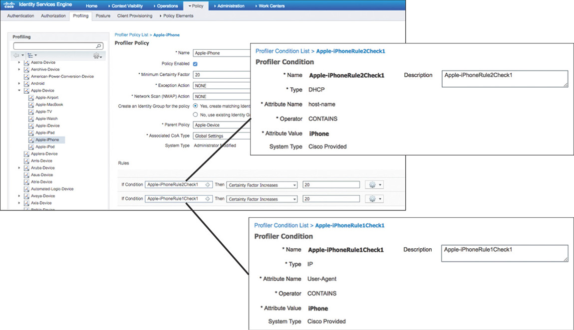
After the device is profiled, its assigned identity group or logical profile can be matched against the conditions in the Authorization Policy. In Figure 5-69 you can see how the device, now that it’s profiled, will match on the iPhone_Devices rule and get assigned the iPhone_RestrictedAccess permissions.

Wireless Device Administration via ISE
We can use the Device Administration service in ISE to authenticate administrators wanting to gain management access to WLCs and Cisco Prime Infrastructure.
The first step is to navigate to Work Centers > Device Administration > Network Resources to add the WLCs and PI as network devices in ISE providing the TACACS+ settings, as shown in Figure 5-70. It’s important to note that each type of platform requires different attributes back from ISE when performing authentication; thus it is recommended to group devices together at minimum by type. (In this example we would use two: WLCs and Prime Infrastructure [PI].)
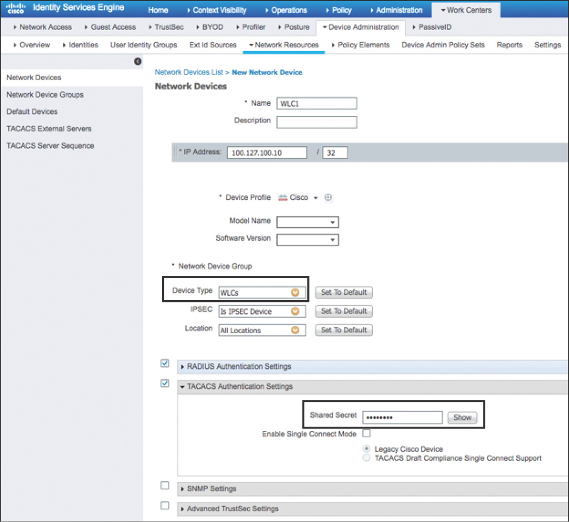
Next, we need to navigate to Work Centers > Device Administration > Policy Results > TACACS Profiles and define the TACACS+ profiles that will be used in the Authorization Policies.
WLCs use custom attributes that need to be defined as roles. The available roles are MONITOR, WLAN, CONTROLLER, WIRELESS, SECURITY, MANAGEMENT, COMMAND, ALL, and LOBBY. As shown in Figure 5-71, these roles are already available as common tasks in ISE, so you just need to enter one or more roles that you want to give access to.
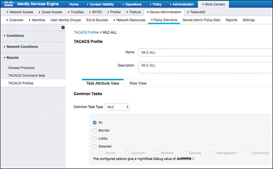
Figure 5-71 TACACS+ Profile for WLCs PI uses the concept of role and task attributes that are specific per user group. These attributes, which are available on PI at Administration > Users > Users, Roles & AAA > User Groups would need to be exported and imported into the TACACS Profiles within ISE, as shown in Figure 5-72.
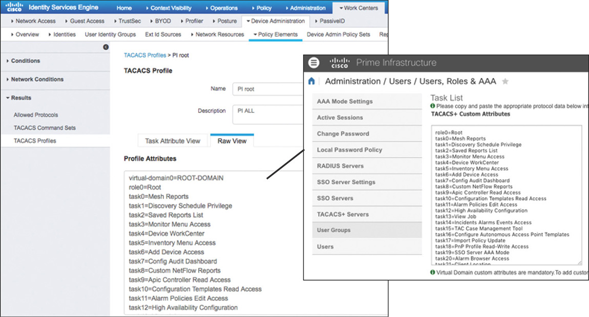
Figure 5-72 TACACS+ Profile for PI
At this point we can start creating our Device Admin Policy like the one shown in Figure 5-73. By default, Policy Sets are enabled to allow organizing policies more easily. In this example the policy set Wireless will be used for devices belonging to the WLCs or PI device groups, as defined by the policy set rules. Inside this set, we can see that authentication is configured to use Active Directory exclusively (it could have been any of the supported identity sources). Finally, the Authorization Policy is set up in a way that users belonging to Active Directory Group1 will have full access to both PI and WLCs, and users belonging to Group2 will have only monitoring access to the WLCs.
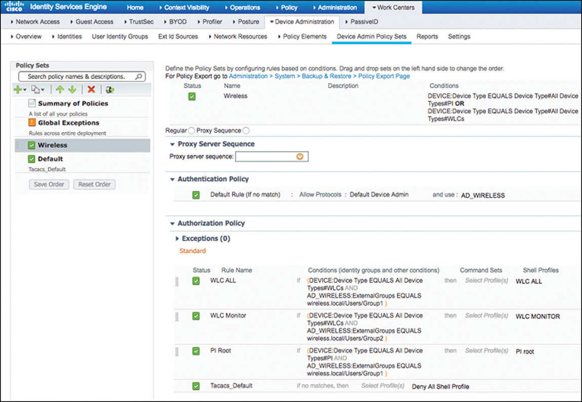
Although this scenario was simple, the policies could be configured to leverage many more attributes in the rule conditions to meet the security policy of the organization with regard to who gets access to manage the different infrastructure devices.
Summary
Because the Cisco Identity Service Engine is such a flexible and feature-rich platform, trying to cover every little feature and detail within the boundaries of a single section of book is impossible. As such, the purpose of this chapter was to provide you with sufficient understanding of how things interact, common flows, and how policies get structured. Having this base knowledge, along with sufficient hands-on practice, will allow you not only to increase your experience but to also develop the creativity required to come up with solutions that meet different use case requirements that you might encounter during your CCIE studies or as part of your day-to-day job responsibilities.