Appendix C. OSI Model, TCP/IP Architecture, and Numeric Conversion
The Open Systems Interconnection (OSI) model is a mandatory topic in any internetworking book. The CCNP candidate should understand the OSI model and identify which OSI layers host the different networking protocols. The OSI model provides a framework for understanding internetworking. This appendix offers an overview and general understanding of the OSI reference model.
The Transmission Control Protocol/Internet Protocol (TCP/IP) architecture provides the practical implementation of a layered model. This appendix is an overview of the TCP/IP layers and how they map to the OSI model.
Also covered in this appendix is the numeric conversion of binary, decimal, and hexadecimal numbers. The ability to covert between binary, decimal, and hexadecimal numbers helps you manipulate IP addresses in binary and dotted-decimal format. Quickly converting these numbers will help you answer test questions.
OSI Model Overview
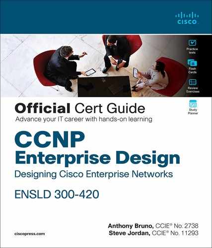
The International Organization for Standardization (ISO) developed the OSI model in 1984, and revisited it in 1994, to coordinate standards development for interconnected information-processing systems. The model describes seven layers that start with the physical connection and end with the application. As shown in Figure C-1, the seven layers are physical, data link, network, transport, session, presentation, and application.
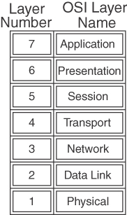
Figure C-1 Seven-Layer OSI Model
The OSI model divides the tasks involved in moving data into seven smaller, more manageable layers. Each layer supplies services to the layer above, performs at least the functions specified by the model, and expects the defined services from the layer below. The model does not define the precise nature of the interface between layers or the protocol used between peers at the same layer in different instantiations of a protocol stack. The model’s design encourages each layer to be implemented independently. For example, you can run an application over IP (Layer 3), Fast Ethernet (Layer 2), Frame Relay (Layer 2), or Gigabit Ethernet (Layer 2). As the packets route through the Internet, the Layer 2 media change independently from the upper-layer protocols. The OSI model helps standardize discussion of the design and construction of networks for developers and hardware manufacturers. It also provides network engineers and analysts with a framework useful in understanding internetworking.
Layered implementations of internetworking technologies do not necessarily map directly to the OSI model. For example, the TCP/IP architecture model describes only four layers, with the upper layer mapping to the three upper layers of the OSI model (application, presentation, and session). The development of IP predates the OSI model. For a more thorough discussion of the TCP/IP model, see Chapter 1, “Internet Protocol Version 4 (IPv4) Design.”
The following sections describe and provide sample protocols for each OSI layer.
Physical Layer (OSI Layer 1)
The physical layer describes the transportation of raw bits over physical media. It defines signaling specifications and media types and interfaces. It also describes voltage levels, physical data rates, and maximum transmission distances. In summary, it deals with the electrical, mechanical, functional, and procedural specifications for links between networked systems.
Examples of physical layer specifications are
EIA/TIA-232 (Electronic Industries Association/Telecommunications Industry Association)
EIA/TIA-449
V.35
IEEE 802 LAN and metropolitan-area network (MAN) standards
Physical layer (PHY) groups Synchronous Optical Network/Synchronous Digital Hierarchy (SONET/SDH)
Maximum cable distances of the Ethernet standards
Data Link Layer (OSI Layer 2)
The data link layer is concerned with the reliable transport of data across a physical link. Data at this layer is formatted into frames. Data link specifications include frame sequencing, flow control, synchronization, error notification, physical network topology, and physical addressing. This layer converts frames into bits when sending information and converts bits into frames when receiving information from the physical media. Bridges and switches operate at the data link layer.
Because of the complexity of this OSI layer, the IEEE subdivides the data link layer into three sublayers for LANs. Figure C-2 shows how Layer 2 is subdivided. The upper layer is the logical link sublayer, which manages communications between devices. The bridging layer, defined by IEEE 802.1, is the middle layer. The lowest layer is the Media Access Control (MAC) sublayer, which manages the protocol access to the physical layer and ultimately the actual media. Systems attached to a common data link layer have a unique address on that data link layer. Be aware that you might find some references describing this layer as having two sublayers: the Logical Link Control (LLC) sublayer and the MAC sublayer.
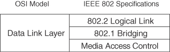
Figure C-2 IEEE Data Link Sublayers
Examples of data link layer technologies are
Frame Relay
ATM
Synchronous Data Link Control (SDLC)
High-Level Data Link Control (HDLC)
Point-to-Point Protocol (PPP)
Ethernet implementations (IEEE 802.3)
Wireless LAN (IEEE 802.11)
Network Layer (OSI Layer 3)
The network layer is concerned with routing information and methods to determine paths to a destination. Information at this layer is called packets. Specifications include routing protocols, logical network addressing, and packet fragmentation. Routers operate at this layer.
Examples of network layer specifications are
Protocol
IPv4, IPv6
ICMP
ARP
Connectionless Network Protocol (CLNP)
Routing protocols
Routing Information Protocol (RIP)
Open Shortest Path First (OSPF)
Enhanced Interior Gateway Routing Protocol (EIGRP)
Intermediate System-to-Intermediate System (IS-IS)
Transport Layer (OSI Layer 4)
The transport layer provides reliable, transparent transport of data segments from upper layers. It provides end-to-end error checking and recovery, multiplexing, virtual circuit management, and flow control. Messages are assigned a sequence number at the transmission end. At the receiving end, the packets are reassembled, checked for errors, and acknowledged. Flow control manages the data transmission to ensure that the transmitting device does not send more data than the receiving device can process.
Examples of transport layer specifications are
Transmission Control Protocol (TCP)
Real-Time Transport Protocol (RTP)
User Datagram Protocol (UDP)
Session Layer (OSI Layer 5)
The session layer provides a control structure for communication between applications. It establishes, manages, and terminates communication connections called sessions. Communication sessions consist of service requests and responses that occur between applications on different devices.
Examples of specifications that operate at the session layer are
DECnet’s Session Control Protocol (SCP)
H.245 and H.225
Presentation Layer (OSI Layer 6)
The presentation layer provides application layer entities with services to ensure that information is preserved during transfer. Knowledge of the syntax selected at the application layer allows selection of compatible transfer syntax if a change is required. This layer provides conversion of character-representation formats, as might be required for reliable transfer. Voice coding schemes are specified at this layer. Furthermore, compression and encryption can occur at this layer.
An example of a specification that operates at the presentation layer is Abstract Syntax Notation 1 (ASN.1).
Application Layer (OSI Layer 7)
The application layer gives the user or operating system access to the network services. It interacts with software applications by identifying communication resources, determining network availability, and distributing information services. It also provides synchronization between the peer applications residing on separate systems.
Examples of application layer specifications are
Telnet
File Transfer Protocol (FTP)
Simple Mail Transfer Protocol (SMTP)
Simple Network Management Protocol (SNMP)
Network File System (NFS)
Border Gateway Protocol (BGP)
TCP/IP Architecture
The suite of TCP/IP protocols was developed for use by the U.S. government and research universities. The suite is identified by its most widely known protocols: TCP and IP. As mentioned, the ISO published the OSI model in 1984. However, the TCP/IP protocols had been developed by the Department of Defense’s Advanced Research Projects Agency (DARPA) since 1969. TCP/IP uses only four layers (as described in RFC 791) versus the seven layers used by OSI. The TCP/IP layers are
Application
Host-to-host transport
Internet
Network interface
Figure C-3 shows how the TCP/IP layers map to the OSI model.
Figure C-3 The TCP/IP Architecture and the OSI Model
Network Interface Layer
The TCP/IP network interface layer (also known as network access layer) maps to the OSI data link and physical layers. TCP/IP uses the lower-layer protocols for transport.
Internet Layer
The Internet layer is where IP resides. IP packets exist at this layer. It directly maps to the network layer of the OSI model. Other TCP/IP protocols at this layer are Internet Control Message Protocol (ICMP), Address Resolution Protocol (ARP), and Reverse ARP (RARP).
Host-to-Host Transport Layer
The host-to-host transport layer of TCP/IP provides two connection services: TCP and UDP. TCP provides reliable transport of IP packets, and UDP provides transport of IP packets without verification of delivery. This layer maps to the OSI transport layer, but the OSI model only defines reliable delivery at this layer.
Application Layer
The TCP/IP application layer maps to the top three layers of the OSI model: application, presentation, and session. This layer interfaces with the end user and provides authentication, compression, and formatting. The application protocol determines the data’s format and how the session is controlled. Examples of TCP/IP application protocols are Telnet, FTP, BGP, and Hypertext Transfer Protocol Secure (HTTPS).
Example of Layered Communication
Suppose that you use a Telnet application. Telnet maps to the top three layers of the OSI model. In Figure C-4, a user on Host 1 enables the Telnet application to access a remote host (Host 2). The Telnet application provides a user interface (application layer) to network services. As defined in RFC 854, ASCII is the default code format. No session layer is defined for Telnet (not an OSI protocol). Per the RFC, Telnet uses TCP for connectivity (transport layer). The TCP segment is placed in an IP packet (network layer) with a destination IP address of Host 2. The IP packet is placed in an Ethernet frame (data link layer), which is converted into bits and sent onto the wire (physical layer).
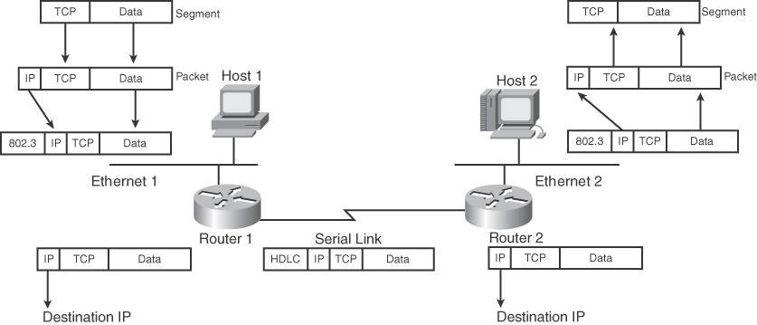
Figure C-4 Telnet Example
When the frame arrives at Router 1, it converts the bits into a frame; removes the frame headers (data link); checks the destination IP address (network); places a serial link header on the packet, making it a serial frame; and forwards the frame to the serial link (data link), which sends it as bits.
Router 2 receives the bits and converts them into a frame; removes the serial encapsulation headers; checks the destination IP address (network); adds an Ethernet header to the packet, making it a frame; and places the frame on Ethernet 2 (data link). Host 2 receives bits (physical) from the Ethernet cable and converts the bits into a frame (data link). Then the IP protocol is examined and the packet data is forwarded to TCP, which checks the segment number for errors and then forwards the segment to TCP port 23 (Telnet), which is the application.
Numeric Conversion
This section focuses on the techniques for converting between decimal, binary, and hexa-decimal numbers. Although the exam might not have a specific question about converting a binary number to decimal, you need to know how to convert these numbers to do problems on the test. An IPv4 address could be shown as binary or in traditional dotted-decimal format. MAC addresses and IPv6 addresses are represented in hexadecimal. Some show commands have output information in hexadecimal or binary formats.
Hexadecimal Numbers
The hexadecimal numeric system uses 16 digits instead of the 10 digits used by the decimal system. Table C-1 shows the hexadecimal digits and their decimal equivalent values.
Table C-1 Hexadecimal Digits
Hexadecimal Digit |
Decimal Value |
0 |
0 |
1 |
1 |
2 |
2 |
3 |
3 |
4 |
4 |
5 |
5 |
6 |
6 |
7 |
7 |
8 |
8 |
9 |
9 |
A |
10 |
B |
11 |
C |
12 |
D |
13 |
E |
14 |
F |
15 |
10 |
16 |
11 |
17 |
12 |
18 |
13 |
19 |
14 |
20 |
Hexadecimal Representation
It is common to represent a hexadecimal number with 0x before the number so that it is not confused with a decimal number. The hexadecimal number of decimal 16 is written as 0x10, not 10. Another method is to put a subscript h to the right of the number, such as 10h. It is also common to use the term hex when speaking of hexadecimal. Much of the following text uses hex.
Converting Decimal to Hexadecimal
First things first: Memorize Table C-1. There are two ways to convert larger numbers. The first method is to convert decimal to binary and then convert binary to hex. The second method is to divide the decimal number by 16—the residual is the rightmost hexadecimal digit—and then keep dividing until the number is not divisible anymore. For the first method, use the schemes described in later sections. For the second method, follow the examples described here.
First, divide the decimal number by 16. The remainder of the division is the least-significant (first) hexadecimal digit. Continue to divide the quotients (answer) of the divisions by 16 until the quotient is 0. The remainder value of each later division is converted to a hexadecimal digit and prepended to the previous value. The final remainder is the most-significant digit of the hexadecimal equivalent. For large numbers, you might have to divide many times. The following examples make the process clearer.
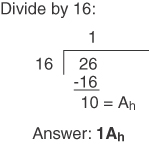
Conversion Example C-1 Convert 26 to Its Hex Equivalent
Conversion Example C-2 Convert 96 to Its Hex Equivalent
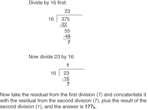
Conversion Example C-3 Convert 375 to Its Hex Equivalent
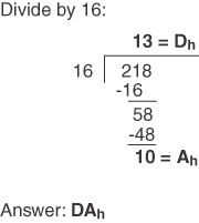
Conversion Example C-4 Convert 218 to Its Hex Equivalent
Converting Hexadecimal to Decimal
To convert a hex number to decimal, take the rightmost digit and convert it to decimal (for example, 0xC = 12). Then add this number to the second rightmost digit multiplied by 16 and the third rightmost digit multiplied by 256. Do not expect to convert numbers larger than 255 on the CCNP exam, because the upper limit of IP addresses in dotted-decimal format is 255 (although Token Ring numbers reach 4096). Some examples follow.
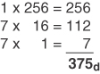
Conversion Example C-5 Convert 177h to Decimal
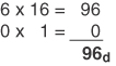
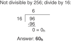
Conversion Example C-6 Convert 60h to Decimal
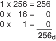
Conversion Example C-7 Convert 100h to Decimal
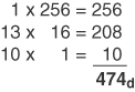
Conversion Example C-8 Convert 1DAh to Decimal
Alternative Method for Converting from Hexadecimal to Decimal
Another way is to convert from hex to binary and then from binary to decimal. The following sections discuss converting from binary to decimal.
Binary Numbers
The binary number system uses two digits: 1 and 0. Computer systems use binary numbers. IP addresses and MAC addresses are represented by binary numbers. The number of binary 1s or 0s is the number of bits, short for binary digits. For example, 01101010 is a binary number with 8 bits. An IP address has 32 bits, and a MAC address has 48 bits. As shown in Table C-2, IPv4 addresses are usually represented in dotted-decimal format; therefore, it is helpful to know how to convert between binary and decimal numbers.
Table C-2 Binary Representation of IP and MAC Addresses
IPv4 Address in Binary |
IPv4 Address in Dotted Decimal |
00101000 10001010 01010101 10101010 |
= 40.138.85.170 |
MAC Address in Binary |
MAC Address in Hexadecimal |
00001100 10100001 10010111 01010001 00000001 10010001 |
= 0C:A1:97:51:01:91 |
MAC addresses are usually represented in hexadecimal numbers; therefore, it is helpful to know how to convert between binary and hexadecimal.
The CCNP candidate should memorize Table C-3, which shows numbers from 0 to 16 in decimal, binary, and hexadecimal formats.
Table C-3 Decimal, Binary, and Hexadecimal Numbers
Decimal Value |
Hexadecimal |
Binary |
0 |
0 |
0000 |
1 |
1 |
0001 |
2 |
2 |
0010 |
3 |
3 |
0011 |
4 |
4 |
0100 |
5 |
5 |
0101 |
6 |
6 |
0110 |
7 |
7 |
0111 |
8 |
8 |
1000 |
9 |
9 |
1001 |
10 |
A |
1010 |
11 |
B |
1011 |
12 |
C |
1100 |
13 |
D |
1101 |
14 |
E |
1110 |
15 |
F |
1111 |
16 |
10 |
10000 |
Converting Binary to Hexadecimal
To convert binary numbers to hex, put the bits in groups of 4, starting with the right-justified bits. Groups of 4 bits are often called nibbles. Each nibble can be represented by a single hexadecimal digit. A group of two nibbles is an octet, 8 bits. Examples follow.
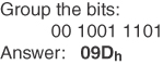
Conversion Example C-9 Convert 0010011101 to Hex
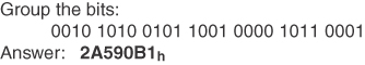
Conversion Example C-10 Convert 0010101001011001000010110001 to Hex
Converting Hexadecimal to Binary
This procedure is also easy. Just change the hex digits into their 4-bit equivalents. Examples follow.
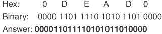
Conversion Example C-11 Convert 0DEAD0 to Hex
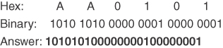
Conversion Example C-12 Convert AA0101 to Hex
Converting Binary to Decimal
To convert a binary number to decimal, multiply each instance of 0 or 1 by the power of 2 associated with the position of the bit in the binary number. The first bit, starting from the right, is associated with 20 = 1. The value of the exponent increases by 1 as each bit is processed, working leftward. As shown in Table C-4, each bit in the binary number 10101010 has a decimal equivalent from 0 to 128 based on the value of the bit multiplied by a power of 2 associated with the bit position. This is similar to decimal numbers, in which the numbers are based on powers of 10: 1s, 10s, 100s, and so on. In decimal, the number 111 is (1*100) + (1*10) + (1*1). In binary, the number 11111111 is the sum of (1*27) + (1*26) + (1*25) + (1*24) + (1*23) + (1*22) + (1*21) + (1*20) = 128 + 64 + 32 + 16 + 8 + 4 + 2 + 1 = 255. For 10101010, the result is 128 + 0 + 32 + 0 + 8 + 0 + 2 + 0 = 170. Examples follow.
Table C-4 Decimal Values of Bits in a Binary Number
Power of 2 |
27 = 128 |
26 = 64 |
25 = 32 |
23 = 8 |
22 = 4 |
20 = 1 |
Binary |
1 |
1 |
1 |
1 |
1 |
1 |
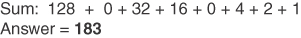
Conversion Example C-13 Convert 10110111 to Decimal
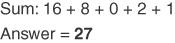
Conversion Example C-14 Convert 00011011 to Decimal
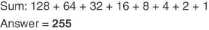
Conversion Example C-15 Convert 11111111 to Decimal
Converting Decimal to Binary Numbers
This procedure is similar to converting from hex to decimal (by dividing), but now you divide the decimal number by 2. You use each residual to build the binary number by prepending each residual bit to the previous bit, starting on the right. Repeat the procedure until you cannot divide anymore. The only problem is that for large numbers, you might have to divide many times. You can reduce the number of divisions by first converting the decimal value to a hexadecimal value and then converting the intermediate result to the binary representation. After the following example, you will read about an alternate method suitable for use with decimal values between 0 and 255 that can be represented in a single octet.
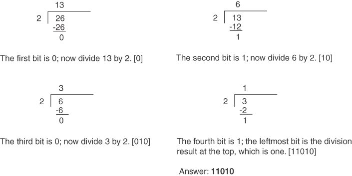
Conversion Example C-16 Convert 26 to Binary
Alternative Method for Converting from Decimal to Binary
The dividing procedure just described works; it just takes a lot of time. Another way is to remember the bit position values within a byte—128, 64, 32, 16, 8, 4, 2, 1—and play with the bits until the sum adds up to the desired number. This method works when you convert integer values between 0 and 255, inclusive. Table C-5 shows these binary numbers and their decimal values.
Table C-5 Bit Values
Binary Number |
Decimal Value |
10000000 |
128 |
01000000 |
64 |
00100000 |
32 |
00010000 |
16 |
00001000 |
8 |
00000100 |
4 |
00000010 |
2 |
00000001 |
1 |
For example, to convert 26, you know that it is a number smaller than 128, 64, and 32, so those 3 bits are 0 (000?????). Now you need to find a combination of 16, 8, 4, 2, and 1 that adds up to 26. This method involves using subtraction to compute the remaining number. Start with the largest number, and make the bit at 16 a 1 (0001????). The difference between 26 and 16 is 10. What combination of 8, 4, 2, and 1 gives 10? 1010. Therefore, the answer is 00011010. You might think this method involves too much guesswork, but it becomes second nature after some practice.
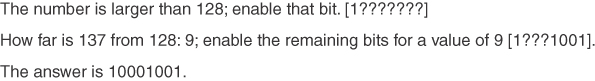
Conversion Example C-17 Convert 137 to Binary
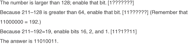
Conversion Example C-18 Convert 211 to Binary
In addition to remembering the bit-position values (128, 64, 32, 16, 8, 4, 2, 1), it helps to remember network subnet mask values. Remembering them makes it easier to figure out whether you need to enable a bit. Table C-6 summarizes the binary subnet mask numbers and their decimal values.
Table C-6 Binary Masks and Their Decimal Values
Binary Mask |
Decimal |
10000000 |
128 |
11000000 |
192 |
11100000 |
224 |
11110000 |
240 |
11111000 |
248 |
11111100 |
252 |
11111110 |
254 |
References and Recommended Readings
ISO/IEC 7498-1: 1994. “Information Processing Systems—OSI Reference—The Basic Model.”
RFC 791: Internet Protocol, www.ietf.org/rfc.
RFC 793: Transmission Control Protocol, www.ietf.org/rfc.