
Isolation shells
There is no space that absolutely cannot be used as a recording studio, so long as it is not subject to any permanent extraneous noises which would intrude upon the recordings. This fact is well borne out in the 1990s by the number of garages, bedrooms, attics, garden sheds and other spaces which are used as studios, sometimes even commercially. So why should we go to great lengths to design and construct a purpose-built studio? Well, the above spaces may suffice for a restricted type of recording, during limited periods of time, or with a limited range of musicians, but they are not usually suitable for high quality work over a wide spectrum of music and instrumentation.
For truly commercial operation, a studio needs to be able to accept recording work of varied nature, and usually needs to be able to record 24 hours a day. The studio should also be capable of working in an efficient manner, without disturbing any neighbours, and without the neighbours disturbing the recordings. Efficiency in terms of time is crucial, because the client may be paying engineers, producers, roadies and musicians by the hour. Delays can be expensive, as the whole team needs to be paid even if the inefficient studio grants extra recording time free, in lieu of time lost. However, more importantly than all of this, musicians cannot be kept waiting if their performances are not to suffer. Delays caused by adjustments for technical reasons, or for disturbances by external noises, can be totally ruinous to the creativity of musicians.
1.1.1 Isolation
One of the prime needs for a viable recording studio is to have a space which is acoustically isolated from the outside world to the degree of about 90 dB. Drums and electric bass, playing loudly in a studio, can achieve levels in the order of 120 dB. A quiet bedroom in the country may have a background noise level of 20 or 25 dBA from a gentle breeze outside, distant traffic, cows moving around in their sheds, or whatever else. In most countries that I know of, legislation does not permit studios, discotheques, or any other ‘industrial’ sources of noise to more than subjectively double the background noise level for any of their neighbours. At mid-frequencies, a subjective doubling of loudness represents an increase of 10 dB, though at frequency extremes, this can be less. In order to play safe, some countries or local authorities will not permit an increase of more than 5 or 6 dB in background noise and some authorities even none at all. However, 5–10 dB on a background noise of 20–25 dB usually renders a situation whereby, if we can avoid raising the background noise level of our neighbours to more than 30 dBA, all will be well. Subtract this allowable 30 dBA at the boundary of our neighbours’ premises from the 120 dBA of the bass and drums in the studio, and we encounter the aforementioned 90 dB isolation requirement. (Readers unfamiliar with the dB and dBA scales should refer to the glossary at the end of the book.)
I use the term ‘subjectively doubling’ in the above paragraph because, in psychoacoustics, subjective and objective assessments very frequently do not closely correspond. In Chapter 6, Figs 6.1 and 6.2 show curves of subjectively equal loudness, spaced apart by the distances of the perceived doubling of sound; that is, the step from any one curve to the next, at any given frequency, represents a perceived doubling (moving up the charts) or halving (moving down the charts) of the loudness. It will be seen that not only do the curves generally not correspond to any objectively consistent doubling, but neither do they show much correlation between different frequencies. Nuisance noise, also, can be perceived to be very different, subjectively, between levels which may have been measured to be objectively similar. Rhythmical sounds, for example, can often be annoying at levels of only a quarter of the power of random noises. It should therefore be emphasised at this early stage that subjective perception may differ considerably from objective measurement.
1.1.2 Siting
It is true that we could site the studios in remote locations, but even if we take earthquakes as an exception, wind, rain, hail, thunderstorms, dogs barking and other country noises can still require considerable isolation if acoustic recordings are not to be interrupted. Of course, there is always the lucky break, such as a space in a building which is surrounded by book depositories, which neither produce noise nor are sensitive to it. These are rare exceptions, but in any case, in industrial areas, such circumstances are somewhat unstable. It may be that a year after building the studio, the book company turns its store into a printing room, with noisy presses which could disturb the studio, or, on the other hand, they could even turn it into a proof-reading room, where the readers would be disturbed by the studio noises.
Choice of location is an important factor, as to site a studio close to a ‘permanent’ book depository would be far more prudent than siting it next to the reading room of a public library, which would simply be asking for problems. In mainland Europe, however, there do seem to be an alarming number of studios on the ground floors and/or in the basements of apartment buildings, which are frequently the only available commercial spaces at affordable rents. Sometimes one cannot have everything, and in these cases, compromises must be accepted. Nevertheless, there are some seemingly obvious locations which should be avoided. Sites near underground and overground railways, together with sites under low-level aircraft flight paths or near to busy roads with fast, heavy traffic will all be likely candidates for low frequency (LF) isolation problems. As all of the above examples produce relatively high levels of low frequencies, and these are the ones most difficult to keep out of the studio in terms of cost-effective isolation.
Locations close to police, fire and ambulance stations are also best avoided, not only because of the potential noise problem from vehicle sirens, but because they often house powerful radio communication equipment, capable of creating many radio frequency (RF) interference problems in sensitive recording equipment. A little careful examination of the surrounding area before a building is chosen as the location for a recording studio can save a great deal of cost and trouble at a later date. Even if the technical staff of a proposed studio are confident that they can adequately deal with the RF problems in their equipment, this still does nothing to prevent problems occurring with the electric or electronic musical instruments which visiting musicians may bring to the studio. I recall one well known guitarist being unable to use a very expensive studio because his favourite guitar was exceptionally sensitive to the electricity company’s data transmissions along some nearby, overhead, high-voltage power lines. I have also known serious problems to develop in studios close to railway lines which have, long after the studios first opened, installed digital signalling and control equipment. In some countries, state-owned railway and emergency services have immunity from prosecution in such cases, so little can currently be done to remedy these problems.
When I worked for Pye Studios in Marble Arch, London, in 1970, there always existed some problems from the rumble of underground trains, deep below. Occasionally this caused disturbances, but in those days, with the troublesome frequencies being so low, and analogue equipment having little response below 40 Hz, it rarely stopped the recordings. However, further along the same street, the studio Recorded Sound (later Nova Sound) was situated on the ground floor of a hotel building, and operation beyond midnight was prohibited. Originally this was thought to be no problem to business, but those involved in delayed or urgent sessions found it severely limiting if the midnight curfew stopped an unforeseen necessary extension, and bad memories of such problems could lead producers to book other studios in future. Neither of the last two studios mentioned exist today, and indeed it is probable that Pye could not have survived into the digital age without much better LF isolation, given the lower frequencies which can be recorded on modern digital equipment. On the brighter side, one London studio, which I regularly visisted, was built in the Lady Chapel of a church that had largely been destroyed by bombs in World War II. This was a perfect choice of location, in a building with massive walls, situated in its own grounds and away from any main roads or railway lines. Construction was relatively inexpensive, results were good, and there were no restrictions on its hours of use. The owners’ choice of location was very prudent, especially since the rent was also reasonable. This good choice of building ensured that construction and operating costs were kept down, so the studio could offer excellent facilities, with good access and few operational restrictions, at an affordable price. Consequently, it has been able to survive some national financial recessions which have forced many more expensively constructed studios, or ones with more restricted usage, to close.
1.1.3 Structural considerations
Not only is siting important, but so is structure. The aforementioned studio in the old church was in an excellent building, but so many of the reinforced-concrete framed structures, very common in southern Europe, resonate intolerably. Reinforced concrete, when used without damping additives, is an excellent conductor of sound. Once sounds get into such structures, they travel throughout the walls and floors with remarkable ease. Buildings made from blocks, interspaced with layers of dirt or cement, meet changes in characteristic acoustic impedances as the sound travels through the different materials of the structure. This leads to losses of acoustical power in the same way that mismatched impedances in an electrical chain would reduce power transfer. On the other hand, poured structures of reinforced concrete produce homogeneous structures, without interspersed materials, so sound is conducted through them very easily. The only simple way of reducing this problem is to add damping materials, such as Concredamp, to the concrete before it is poured, which, of course, must be done during the construction of the building, so it cannot help with an existing structure.
1.1.4 Power transfers
So, careful choice of site and structure can make life much easier for a studio designer and less expensive for a studio owner, but, in almost all cases, some sort of isolated structure will be required if a very high degree of sound isolation is to be realised. Ninety dB of sound isolation represents only one part in a thousand million (10–9) of the sound power in the room escaping to the outside world. Even 60 dB of isolation will allow only one part in a million (10–6) of the sound power to escape. These figures help to put into perspective the degree of isolation work which may be necessary.
As explained earlier, one of the main benefits of a heavy, stone-walled building, with dirt infill, is that there are differences in acoustic impedances between the layers of construction materials. Most people reading this will probably be aware of impedance ratings for microphones and loudspeakers. Connecting a 10 K ohm microphone into a 600 ohm input will not provide a good electrical power transfer of the microphone output to the amplifier input. The connexion of a 16 ohm loudspeaker to an amplifier output rated for 4 ohms will not be able to employ the full output power capability of the amplifier. For maximum power transfer, the source and destination impedances must be matched. The effectiveness of most sound isolation techniques thus involves mismatching of acoustic impedances, to produce a series of power losses as the sound passes from one material to another.
Some knowledge of these impedances is required for a design to be effective, as impedances do not always follow obvious physical properties. Many people will recall seeing films of submarine warfare, where the submarines have to remain as silent as possible, with all motors and machinery stopped, when being chased by destroyers. Typically, on a destroyer, there would be sailors wearing headphones and listening via hydrophones, lowered into the water, for any sounds from the submarine. A dropped screwdriver, or other hard object, in the submarine would rapidly give away its direction to the pursuing destroyer. The reason why the submarines had to remain so incredibly quiet in order to avoid detection is because the seawater and the steel of the submarine hull have almost identical acoustic impedances, so the sound transfer from one material to the other was highly efficient. Modern submarines are now usually completely covered in rubber, the acoustic impedance of which is very different from steel or water. The sound passes inefficiently across the steel/rubber boundary, then equally inefficiently across the rubber/water boundary. The ease with which a destroyer can listen in to the inner sounds of such submarines is thus greatly reduced.
1.2 A typical isolation structure
This book is not intended to be a textbook covering all situations of sound isolation, so suffice it to say that the variables in this area are very great, and the techniques for dealing with them are multitudinous, so we can only deal with some examples here. Nonetheless, with what follows, we should be able to gain a good understanding of many of the problems in general, and also gain a feel for some ways of solving them. Precisely how to begin designing an isolation shell depends on many factors including the available space, the nature of the structure, and the strength of the floor. On the fourth floor of a building with a wooden frame, for example, it would be unlikely that the weight of a concrete-block wall structure would be supported, so other means of isolation would need to be adopted. However, we cannot continue our discussions about room acoustics unless we have a suitable room to begin with, so let us go through the structure of one option in terms of its isolation shell. Let us suppose that we are on a ground floor, which is a very common situation, and one in which a concrete-block wall would be feasible.
1.2.1 Isolation walls
It was stated earlier that dirt-filled, stone-block walls are usually good for isolation. Well, we can conveniently simulate such a structure from more convenient materials by building our walls from high-density concrete blocks of the hollow variety. These are frequently made in sizes about 50 cm
20 cm 20 cm, with central dividers. They are closed on all surfaces but one, and can easily be filled with sand. If we build such a wall inside our building, with an air space between this wall and the structural wall, we can achieve an effective start to our isolation process. The concrete/sand/concrete cross-section of the largest surface area of the wall creates an impedance mismatched sandwich, which is both heavy, and highly damped by the friction of the sand particles. This damping is easily demonstrated by tapping an empty block with a hammer, whereupon a clear ‘ring’ will be heard. Once full of sand its response to a hammer blow will be decidedly dead. The sand should, if possible, be dry, as wet sand will take months to dry out and will risk spreading its dampness into the rest of the structure. The great weight (mass) of such a structure is an important factor in the effectiveness of its low frequency isolation.
The space between our internal and external walls is also of importance, as the air space provides another impedance ‘barrier’ which must be crossed. In general, the larger the air space the better the isolation, but studio owners rarely like to not be able to see the space which they are paying for, so air gaps in general tend to be small. It should be noted here that with greater air gaps, lighter wall structures can often achieve similar isolation, which is one answer to the floor loading problem in lightweight buildings, but the price to be paid is in the loss of space. The effectiveness of a smaller than optimal gap can be augmented by filling it with a material of high frictional loss, such as mineral wool or glass wool, which can also be advantageous in preventing resonances within the cavity from reducing the effectiveness of the gap.
If we were to build an isolation wall in the way described above, we would by now have a wall and an air gap to provide some isolation, but we would also have the equivalent of an electrical short-circuit between the two walls, created by their common floor, and any contact with the structural walls or ceiling must also be avoided. We must therefore create a structural discontinuity to prevent this bridging of the gap, and the usual method is to ‘float’ the isolation wall on a resilient material such as rubber, mineral wool, high-density foam, or suitably damped metal springs. In fact, perhaps it will be easier to visualise many of these things if this chapter now bases itself around an actual set of plans. Figure 1.1 shows the plans of a studio built on the ground floor of an apartment building in Granada, Spain, in 1995. The building was of the reinforced-concrete framed type shown in Fig. 1.2, but the situation was complicated by the fact that the bedroom of an apartment was located directly above the area intended for the recording of drums. The isolation structure used the above-mentioned sand-filled concrete block walls and, in this case, the walls, in this instance floated on a high-density synthetic foam of 5 cm thickness.
Float materials must be chosen such that when they are fully loaded by the weight of the structure placed upon them, they are in the middle section of their compression range. If a material is compressed too little, for example by being too hard, it will transmit the vibration. If it is too highly compressed, it will again become hard, or ‘solid’, for example when a spring is fully compressed, and again the vibrations will be transmitted. Only in the middle loading range will the positive and negative vibrational loads be absorbed by the material. This concept is shown diagrammatically in Fig. 1.3.
1.2.2 Lining the main structure
In the particular case under discussion here, due to the resonant nature of the building shell, the room was lined with 5 cm of high-density mineral wool and two layers of 18 mm plasterboard. The materials were all mounted with a strong, fast drying plaster/adhesive compound (Placoplatre). The plasterboard/mineral wool combination provides a ‘mass and spring’ combination, or, if the structural wall itself is taken into account, a ‘spring sandwich’ (mass/spring/mass). In situations like this it is the order of combination which is critical. Sticking the plasterboard to the wall and the mineral wool on top would not be as effective, as the ‘spring’ (the mineral wool) would no longer be sandwiched between the high mass layers, and waves penetrating the spring would then impinge directly on the plasterboard. As this would be rigidly coupled to the structural wall, the vibration would then pass directly into the structure. True, the plasterboard would add some mass, but the extra mass added in comparison to the mass of the wall would be minimal. When the mineral wool is in the middle of the sandwich, the sound waves must expend energy in moving the heavy plasterboard, which is damped by a great surface of resilient mineral wool. The mineral wool absorbs much of the vibration, and, as it is fibrous in nature, transmits it only poorly to the heavy mass of the structural wall. As we shall see later, low-density and non-rigid materials have trouble transmitting energy to high-density materials. The mineral wool and plasterboard, bonded to this structural wall, also help to damp the resonances of the structure itself, and so also contribute to the rapidity with which vibrations will decay within the main walls of the building.
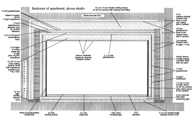
Figure 1.1 Triple isolation shell
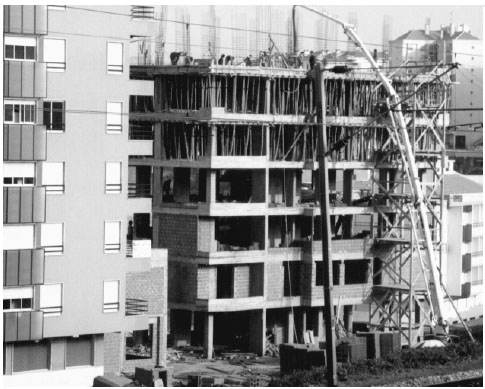
(a) The tube of the concrete pump can be seen extending from the transporting vehicle on the ground, to the top floor of the building where a floor is being cast. The fine steel rods, projecting from the top of the building, will form the core of the next set of vertical pillars
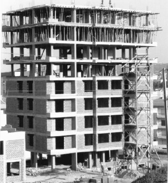
(b) The completed frame of the building can be seen. In the foreground are piles of hollow bricks, which are used to fill in the spaces between the cast-concrete frame. Without the use of damping compounds in the concrete, or the in-filling of the bricks with sand (which would reduce their thermal insulation properties), such structures tend to be very resonant and have poor low frequency sound isolation
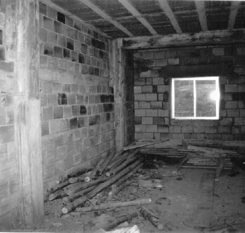
(c) A typical interior of a concrete-framed building
Figure 1.2 Typical European building technique
Because plasterboard is composed of fine particles, there are great frictional losses as waves try to propagate through it. The acoustic energy is largely turned into heat energy as the particles rub together. Similar frictional losses exist between the fibres of the mineral wool in the sandwich, but here, the bending of the fibres, as they act as springs, causes further losses of acoustic energy. (The complex nature of the losses in fibrous materials are discussed further in Chapter 7.) In such sandwiches as being discussed here, the low frequencies have little problem in passing through the fibres of the mineral wool, so its only real use in terms of low frequency isolation is when it is used as a spring between two relatively high mass layers. This is indeed the case when mineral wool is used as a ‘float’ under concrete walls, or floors, again as we shall see later. In fact, fibrous materials can be used to stop low frequencies, but usually only when unrealistic thicknesses are used, or when they are located at either ¼ or ¾ wavelength distances from reflective walls. Again, this will be discussed in more detail in Chapter 7.
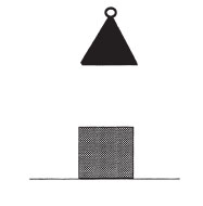
(a) Here we see a weight, suspended above a block of material, intended for isolation
(b) In this illustration, the weight is resting on the block, but the block shows no sign of compression. Its stiffness must therefore be very great, effectively making a rigid coupling between the weight and the ground. Vibrations in the weight (if, for example, it was a vibrating machine) would be transmitted to the ground
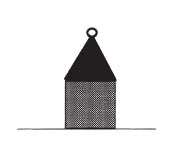
(c) Here the isolation material is too soft, and the weight has compressed it down to a very thin layer. The density and stiffness of the material below the weight will thus increase, and the effect will be an almost rigid coupling with the same effect as in (b)

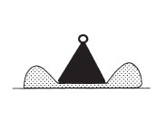
(d) In this illustration, the weight can be seen to have compressed the isolation material to about half its original thickness. The system is at rest due to the equilibrium being found between the gravitational down-force on the weight, and the elasticity of the material. Vibrations in the weight will be resisted by gravity, in the upward direction, and downwards by the mass of the floor and the elasticity of the isolating material. Much of the vibrational energy will be turned into heat by the internal losses in the isolation material, and hence will not be transmitted into the ground
Figure 1.3 Float materials need to be in the centre of their compression range for most effective isolation
In Fig. 1.1 it can be seen that there is a further fibrous layer in the ‘air gap’ between the plasterboard and the floated concrete-block wall. This is lower-density mineral wool, which is used to suppress any longer wavelength sounds circulating in the space. Low frequency waves crossing the gap directly will be little affected by the mineral wool, but situations can develop where waves propagate laterally, effectively circulating in the void. Anything circulating parallel to the walls will have to pass constantly through the mineral wool infill, which will increase the losses and thus help to absorb this energy.
1.2.3 A floated floor
Once we have four isolated walls, we then need a floor. In the case shown in Fig. 1.1, a layer of 8 cm, high-density mineral wool was laid on the floor, on top of a membrane of heavy-duty PVC. The membrane acts as a barrier against any dampness that may exist in the structural floor. A further layer of PVC was then laid over the mineral wool, both to prevent any excess moisture entering from above when an 8–10 cm layer of concrete was poured on top of it, and also to prevent the concrete, itself, from penetrating the upper part of the mineral wool. Once dry, any cement in the mineral wool could make the upper section more rigid, and so would effectively reduce the thickness of the ‘spring’ layer. Inside the concrete was laid an iron-grid structure for extra strength and the prevention of cracking under load. Once the concrete was thoroughly dry, it was covered with a 2–3 cm layer of dry sand, partly for levelling the surface and partly for acoustic damping of the chipboard, plywood and wood-strip layers which would subsequently form the final surface of the floor of the room. The three wooden surface layers were laid in an overlapping pattern, such that the joints between the boards did not coincide. After each layer had been glued to the other as it was laid, and pinned with small nails before the glue dried, the overall result was a single composite layer, free of any noticeable resonances.
It should be noted here that the whole floor was laid inside the isolation walls. There was a space of about 2 cm all around between the floor and the wall, filled with mineral wool. There were two main reasons for this. Firstly, any vibrations transmitted directly into the floor, from bass guitar amplifiers or drum kits, for example, would not be directly coupled to the isolation walls. These isolation walls would therefore only have to deal with airborne noise, making their job much easier. Secondly, if the isolation walls were built directly on the floated floor, the float material under the concrete would have to carry enormous loads around its perimeter, where it would also be carrying the weight of the walls and ceiling. The uneven weight distribution over the surface of the floor would put great stress on the concrete slab, and make a difficult job of having to grade the floating material to be gradually more dense towards the edges. Remember, the float material must be in the middle section of its compression range, as if it is too highly compressed it will not isolate effectively. When the walls and floor are floated separately, the appropriate thickness and density of float material can be chosen for each one. This is explained diagrammatically in Fig. 7.3.
In the case of the room under discussion here, the mineral wool slabs were laid in their normal sense, fibres running horizontally, but it has been shown that greater isolation, for any given thickness, can be achieved by cutting thick blocks of mineral wool across the grain of the fibres, and laying them in smaller sections with the fibres running vertically. In effect it is like laying a floor on a giant scrubbing brush. However, the mineral wool laid in this way needs to be tightly laterally compressed, and restrained around its perimeter, if it is not going to disintegrate as time passes.
1.2.4 Capping the box
All that we now need to complete our isolation shell is a ceiling. A reinforced-concrete ceiling would be an excellent starting point, but when there is little space above, pouring such a structure is difficult. It also takes time to prepare, time to set, and time to dry. Figure 1.1 shows a composite ceiling structure which is relatively easy to construct when there is only minimal space above, and which requires no special skills to do so. The walls in this instance were built to a height of approximately 25 cm below the plasterboard/mineral wool lining of the structural ceiling. The narrowest dimension of the room was only 6 m, so the ceiling could be spanned by timber beams of 20 cm 7 cm, spaced at 60 cm intervals. In a larger room, however, composite beams of timber and plywood, or steel joists, would be needed to securely span the greater distance. In the latter case, if necessary, timber could be attached to the steel for easier fixing of the subsequent layers.
From Fig. 1.1 it can be seen that two layers of plasterboard, each of 13 mm, were attached to the underside of the joists. This was done with large screws and large washers to distribute the load. The plasterboard layers were fitted with overlapping joints, with the board junctions of one layer connected to one joist, and the joints in the next layer connected to the next joist, and so forth alternately, as shown in Fig. 1.4. When each pair of joists was covered by the first layer of plasterboard, an infill of fibrous material was laid in the spaces between the joists. This stops any ‘chatter’ in the 20 cm (or so) cavity between the two plasterboard surfaces, formed by the inner layer of the structural ceiling and the upper layer of the isolation shell ceiling, and damps any cavity resonances which could reduce the isolation. In practice, the fibrous material could be mineral wool, glass-fibre wool, or heavy cotton-waste felt.
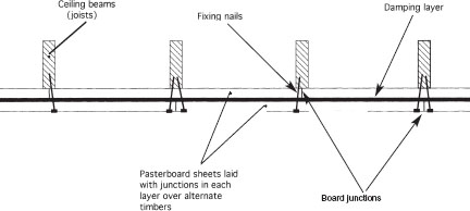
Figure 1.4 Fixing arrangement of plasterboard sheets
It will also be noted from Fig. 1.1 that there exists a layer of deadsheet between the two layers of plasterboard. In actual fact it was a layer of bituminous composite sheeting weighing 4 kg/m2. Further effectiveness could have been gained by using products such as Revac, or Noisetec LA5 or LA10. These deadsheets have available weights of 5 and 10 kg/m2 and are very effective in improving the low frequency isolation. They are plasticised, mineral-loaded products which come in rolls of about 5 m 1 m and are relatively resistant to fire. Not only do they act as very non-resonant extra mass layers, but they also act as ‘constrained layers’ between the plasterboards.
Constrained layer technology is very effective at vibration damping. It is shown diagrammatically in Fig. 1.5, where it can be seen that a viscous layer, sandwiched exactly halfway between two identical flexing layers, will try to shear throughout its entire surface as the composite structure is flexed. Shearing forces over such a great area are very strongly resisted, and thus the flexing vibrations are very heavily and rapidly damped. This sort of composite layer can produce around 30 dB of isolation at 50 Hz, which given its simplicity and flexibility can be a very useful option to have available. However, one needs to be careful with the choice of the density of the constrained layer; if it is too heavy it will reflect more energy back into the room, but if it is too light it will not absorb sufficiently. A density of 4 kg/m2 is a reasonable compromise for such a layer between two 13 mm plasterboards for maximum LF absorption relative to transmission and reflexion. As we pass from the isolation wall to the innermost surfaces of the room though, we need to become gradually more concerned with internal acoustic control, and less with pure isolation, so we will see later how these materials may be used in other ways.
1.2.5 The need for a second ceiling
In the actual building referred to here, the basic structure yielded 30 dB of isolation. A bass guitar and drum kit played on the ground floor was registering peaks in the room of above 113 dB. Measurements taken simultaneously in the bedroom above gave readings of 83 dB, and at such levels it would have been impossible to enjoy a television programme, let alone to sleep. The 30 dB, or thereabouts, of extra isolation provided by the floated room and composite ceiling described in the last few paragraphs could reduce that to about 55–60 dB (bass guitar and bass drum fundamentals being well below 50 Hz, see previous paragraph) but 60 dB is the level of a normal conversation in the room, so isolation would still be far from adequate. Given the relatively massive structure of the floated walls and floor, it is clearly the ceiling, in this case, which is the weakest surface of the room, and unfortunately it is the surface directly facing the problem of the bedroom above. To increase the isolation, it was decided to add a very different type of layer below the first composite ceiling. This consisted of a layer of reconstituted polyurethane foam, with a thickness of 4 cm and a density of 80 kg/m3. It was attached to the plasterboard above by contact adhesive, and below were glued two further layers of 13 mm plasterboard with their joints overlapping so that no edges of the two layers were coincident.
![]()
(a) Damping material fixed to flexible panel
(b) When panel is flexed in this direction, the damping material (shaded layer in diagram) will stretch
(c) When flexed in this direction, the damping layer will compress
![]()
(d) Damping layer sandwiched between two similar flexible panels
(e) When flexed, the top layer will stretch and the bottom layer will compress. The damping layer, however, will remain the same length, but, if viscous, will attempt to shear throughout its entire area, down its centre line. The forces resisting this are very great indeed and, consequently, so is the damping provided by the constrained layer
Figure 1.5 Constrained layer damping principle
It often seems to worry people when they see such a weight of plasterboard suspended solely by adhesives from a foam ceiling. The foam is similar to that frequently found in flight cases – the multi-coloured stuff – but it is cut in a different orientation to the usual manufacturing process. I often demonstrate with a small square, say 10 cm 10 cm, which I stick to a ceiling, then continue to attach two 10 cm squares of plasterboard to the foam using the same contact adhesive. ‘Yes’ people often say, ‘but that is only a small piece, you are planning to put tons up there!’ What they so often fail to realise is that the kg/m2 pull is exactly the same, whether it is 10 cm2 or 100 m2. The foam itself has a resistance to traction of around four tons per square metre, and the strength of the contact adhesive used is only slightly less, which is over one hundred times the strength necessary to support a double 13 mm layer of plasterboard.
This sort of structure acts somewhat like a boxer’s punch-bag, with the plasterboard taking the initial energy of the blow, and the foam subsequently absorbing it as it is trapped between the two mass layers. A deadsheet layer was not used between the plasterboard sheets, in this instance, as the plasticised sheets are apt to reject the adhesive and weaken the structure. The whole ceiling thus formed a highly damped vibrating membrane, perhaps with a total isolation at 40 Hz of around 40 to 50 dB.
The reason why different types of isolation structures were used for this ceiling, as opposed to just using more of the first technique, is that all isolation systems have certain characteristic resonances. These resonances can cause weak spots in the isolation, so if a second identical system is used, these weak spots will occur at the same frequency. However, when an entirely different isolation system is used, it is less likely that any resonances will coincide so, effectively, each system largely covers any weaknesses in the other.
1.2.6 First considerations of internal acoustics
It was not, however, solely for its isolation properties that this type of ceiling was used. As will be described in later chapters, the isolation shell can have its effects on the internal acoustics of the finished room. Although the concrete wall and floor structures are good at preventing sound transmission, they do so by reflecting much of the sound back into the room. Effectively, they are containment shells. By contrast, using a highly resilient ceiling provides isolation by achieving a great deal of low frequency absorption, which, in conjunction with the walls and ceiling, achieves perhaps 50 dB of wideband isolation without an undue low frequency build-up in the space within, though they do reflect mid and high frequencies.
1.2.7 General comments on the shell
Thus, what we now have is a fully floated isolation shell, penetrated only by doors, ventilation ducts and possibly windows, and ready for the internal acoustic treatment. As mentioned earlier, this is not intended to be a book on sound isolation, which is a truly enormous subject, but an isolation shell should normally be a starting point for most acoustic designs for the studio rooms. Without at least a little understanding of the point from where we usually begin the internal designs, many of the concepts of the following acoustic designs would be without foundation, and it would leave too many gaps in the information to which we may need to refer back. At least a basic understanding of some of the isolation concepts is therefore a necessary starting point.
The isolation shell described here is not in any way definitive, but it is an interesting example as it incorporates a number of different techniques, a description of which helps to give a reasonably broad grounding in the different processes which we may encounter. There is a huge variety of products on the international market for isolation materials, and different designers will have many of their own favourite materials and methods. There are literally dozens of ways of approaching the design of a room similar to the one described here, and costs, availability of materials, availability of appropriate labour, weight considerations, humidity or insect problems, and many, many other things may all have a bearing on the precise method chosen.
In the specific case described, tight budget restraints, availability of local labour and materials, and speed of construction all had their parts to play in why the room was built the way it was. In the end, after the construction of an internal acoustic control shell and surface treatments, it eventually yielded 83 dB of isolation from a bass guitar and drum kit in the studio to the bedroom directly above. Above 100 Hz, the isolation increased rapidly, and so for acoustic instrument use, except for bass drums and tympani, even in the middle of the night it would be impossible to play at such a level as could be detected above the minimum background noise in the bedroom above. The 113 dBA of the typical bass and drums set-up produced a noise level of 30 dBA in the bedroom. It was considered that, whilst some ‘extreme’ cases could perhaps produce 120 dB in the studio, the owners of the studio in Granada considered that these cases would be too few and far between to render necessary the expense of extra isolation. Indeed, after one year of unrestricted use, they had not received one, single complaint from their neighbours.
There also had been a battle between the space needed for isolation and the demands of the owners for the maximum available internal space. To yield 90 dB of isolation it would have been possible to use 10 cm foam on the ceiling, an extra 2 cm of concrete on the floor and, perhaps, the use of a 10 kg/m2 deadsheet in the isolation sandwich of the ceiling, plus a little more mineral wool of higher density between the joists. However, these measures could have reduced the available ceiling height by around 10 cm, and as there was only 3 m 44 cm of available height in the original building, the owners absolutely refused to allow another 10 cm to be ‘lost’ to isolation. The results were ultimately deemed acceptable by the studio owners, the musicians and the neighbours above. Compromise is very much a part of the job of a studio designer; however, I have learned the hard way that when the compromise point seems too limited on any aspect of the design, it is better to refuse the job, no matter how much it may be wanted by any of the parties involved. To go ahead tends only to lead to bad feeling and future problems. Some spaces are just not suitable to be studios, and that point must be clearly understood. In the excitement of the planning stages, many studio owners agree to performance limitations which the designer may advise them against, but they often rapidly forget their acceptance of the limitations once they have spent all of their money and the reality of the limitations strikes home. Clearly, warning of expected limitations is an important part of the work of a studio designer, and those warnings will largely be based on a wealth of experience and they should be very carefully considered. If this type of advice is dismissed too casually, it can prove very expensive in the long term.
Anyhow, what has so far been described in this chapter is a viable isolation shell, which in the vast majority of cases will consist of four vertical walls, a floor, and a ceiling. The shell, at this stage, will probably sound highly unmusical as it will possess strong resonances at frequencies which correspond in wavelength to the room dimensions. The reason for this is because most of the isolation has been achieved by reflecting the energy back into the room, so clearly, something must be done to rectify this situation. The following five chapters will look at what we can do inside the isolation shells in order to create environments which are sonically appropriate for various types of musical performances and recordings. However, before we proceed any further, perhaps we should consider what goes on inside the bare isolation shells, as this will give us some insight into why the work described in the following chapters is necessary.
Sound consists of tiny local changes in air density which propagate through the air as a wave motion at the speed of sound. The speed of sound is around 340 m per second at normal room temperature and, although it is temperature dependent, it is independent of variations in the ambient pressure, and is the same at all frequencies. The frequency of a sound wave is measured in cycles per second (c/s or cps) known more usually nowadays as hertz (Hz), and is usually represented by the symbol f. The distance that a sound wave travels in one cycle at any frequency is known as the wavelength, represented by the symbol (lambda), and is measured in metres. The speed of sound is represented by the symbol c. The relationship between wavelength, frequency and the speed of sound is simple; wavelength is equal to the speed of sound divided by the frequency; or = c/f. So, for example, a sound wave at a frequency of 34 Hz has a wavelength of 340/34 = 10 m.
As a sound wave propagates away from a source in a room, it will expand until it reaches a reflective room boundary, such as a wall, from which it will reflect back into the room. The reflected wave will continue to propagate until it reaches other boundaries from which it will also reflect. If there is nothing in either the room or the boundaries to absorb energy from the wave, the propagation and reflexion will continue indefinitely, but in practice some absorption is always present and the wave will decay with increasing time. The point on the cycle of a sound wave (the phase of the wave) when it reaches the boundary depends upon the distance to the boundary and the frequency of the wave. Figure 1.6 shows how waves at different frequencies, propagating from the same source, arrive at a boundary with different phases.
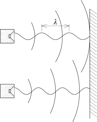
Figure 1.6 Phase relationship of reflected waves. Sound waves of different frequencies, and hence of different wavelength, emanating from a sound source with the same phase relationships, will, after travelling identical distances to a reflective boundary, arrive at the boundary with different phase relationships. From the above figure, it can be seen that the two waves leave their respective sound sources at a positive peak of their cycles, but arrive at the wall quite differently
A rigid boundary will change the direction of propagation of an incident sound wave, but will maintain its phase, so the phase of a reflected wave can be calculated from the total distance propagated from the source. If this total distance is equal to a whole number of wavelengths then the wave will have the same phase it started with. When two boundaries are parallel to each other, a sound wave will reflect from one boundary towards the other, and then reflect back again to where it started, continuing back and forth until its energy is dissipated. If the distance between the boundaries is such that the ‘round trip’ from the source to the first boundary, on to the second boundary, and back to the source is a whole number of wavelengths, then the returning wave will have the same phase as the outgoing wave and will serve to reinforce it. This situation is known as resonance. Resonances can also occur due to reflexions from multiple boundaries; the necessary requirement being that the sound wave eventually returns to a point with the same phase as when it left. One can imagine a whole set of possible combinations of reflexions in a typical room which allow the wave to return to its starting point, and therefore a whole set of frequencies for which resonance will occur. In fact, in theory, every room has an infinite number of possible resonances.
As stated above, if there is nothing in the room or the boundaries to absorb energy from a sound wave, a short duration sound pulse (or transient) emitted from a source will propagate around the room indefinitely. Of the infinite number of possible paths that the wave can take, only those which correspond to resonances at frequencies contained in the pulse will be continually reinforced; all other paths will decay rapidly. After a short time, the resulting sound field can be thought of as simply a sum of all of the resonances that have been excited. These resonant paths are known as the natural modes of the room and the resonant frequencies are known as the natural frequencies, or ‘eigentones’, of the room; both are determined uniquely by the room geometry (‘eigen’ is German for ‘own’, so the eigentones are a room’s own particular, natural, resonance frequencies).
When sound absorption occurs within the room or boundaries, resonant modes still exist, but the wave will decay at a rate determined by the amount of absorption. To maintain a given sound level in a room in the presence of absorption, the source needs to be operated continuously at a level dependent both upon whether or not resonant modes are being excited, and the amount of absorption present. When the sound source emits a transient signal in the presence of absorption (for example, switching off a continuous signal), many different paths – not just resonant modes – will be excited, but after a short time, only the resonant modes will remain; the room will ‘ring’ at the resonance frequencies until the modes decay. The reverberation time of a room is a measure of the average rate of decay of the sound in the room when an otherwise continuous sound source is switched off; it is the time taken for the sound level to fall to – 60 dB relative to its initial, continuously excited, level. As the amount of absorption is increased, the sound level at the resonant frequencies will reduce but the bandwidth of each mode (the range of frequencies over which the mode can be excited to a significant degree) will increase. When the boundaries are fully absorbent the room modes no longer exist (an anechoic chamber).
When sounds such as speech or music are heard in a room, the level of the continuous components of the sound will be determined by whether or not they coincide with any room resonances that are excited. The transient components will ‘hang on’ at the resonance frequencies after the transient has gone.
The above topic will be expanded upon as we progress, but our job, in whatever direction we seek to develop the acoustics of a room, will be to control the room modes. In such a way, we can create rooms which have the required degree of musicality for our purposes, such that the response is what we want, and is not restricted to a response which is dominated by the eigen-frequencies of the isolation shell. In order to achieve this, we can use geometry to control the pathways (and hence the resonance frequencies), and absorbent materials to both control the level of reflexions and the spread of frequencies which contribute energy to specific modes.