
Stone rooms
Live rooms have been constructed from wood, metal, glass, ceramics, brick, concrete and many other reflective materials. Undoubtedly, the materials of construction affect the timbre of the resulting sound and it is very difficult, if not impossible, to make one material sound like another. I frequently use wood in live areas, but largely due to the success of certain early rooms, I seem to be asked to build stone rooms more frequently than others. Stone is unique amongst the other materials in that its surface, in a readily available state, is far less regular and hence more diffusive than the other materials. Hard stones sound different to soft stones, just as hardwoods sound different to softwoods. No one live room can be all things to all people, but where a specific live room is required, as opposed to a live area within a room, stone does seem to be a particular favourite for many. The widespread use of stone rooms is a relatively recent phenomenon and, as with so many other aspects of the recording industry, its origin and acceptance can be traced back through some quite unpredictable chains of events. Certainly the evolutionary path of the many rooms which I have built could neither have been foreseen nor controlled.
Twenty-four track tape recorders became generally available in early 1973, bringing what was an unprecedented luxury of being able to record drum kits using multiple microphones on a one microphone to one track basis. Seven years earlier, anything more than two or three microphones and one track of the tape recorder for a drum kit was seen as either wanton extravagance, or the actions of an ostentatious ‘prima donna’ engineer. Almost inevitably, the one microphone to one track recording technique led to experimentation in the recording of drum kits. Equalisation of the individual drums in the kit was a novelty that was much pursued, but the desired signal processing was seen to be being made less simple or effective by overspill from adjacent drums in the kit picking up on the other microphones. The answer seemed to lie in increased acoustic separation, which led in turn to studio designers being asked to produce isolation booths which not only separated the drum kit from the rest of the instrumentation, but also enabled a new degree of separation between the individual drums within a kit. The mid-1970s witnessed the industry experiencing the aberration of the use of very dead drum booths, which were later to be largely relegated to use for the storing of flight cases or microphone stands.
The highly damped drum booths had enabled the period of experimentation with separation to run its course. Achieving separation was undoubtedly facilitated by the use of these booths, but unfortunately, they posed two major problems. Firstly, once the novelty of individually equalised and processed kits had begun to wear off, the essential ambient ‘glue’ which held a kit together was conspicuous by its absence. Secondly, and probably even more importantly, most drummers did not enjoy playing in these booths. An uncomfortable drummer can rarely produce an inspired performance, and as an excellent recording of an uninspired performance would rarely last the test of time, it soon became apparent that the human requirements of the drummers required far more attention paying to them than had previously been allocated: at least, that is, if inspired performances were required. Drummers soon began moving back into the main studio areas, often reverting to the older practice of being shielded behind acoustic screens, but the re-recognition of the importance of ambient ‘glue’ to hold a kit together was beginning to signal the end of the dead isolation booths for the drums.
My personal recollection of the advent of the stone rooms began in early 1978 when I was discussing the designs for Townhouse One, in London, with Tom Hidley and Mick Glossop (who had been scheduled to be the chief engineer when the Townhouse opened). I remember pushing hard for at least one of the four isolation booths to be given a live acoustic, especially as I had envisaged (wrongly) that once open, the Townhouse would have relied to a much greater degree on ‘session’ work with strings and brass, rather than the ‘lockout’ rock music bookings which became its bread and butter. I managed to gain a consensus that we should have a wooden floored, wood/glass/mirrored walled room at the back of the studio. Mid-way through that year, Richard Branson decreed that a second recording studio was to be constructed in place of the originally proposed rehearsal room. Many aspects of the two control rooms were to be similar, but this time, in the second studio, there was to be scope for experimentation.
I proposed a stone room, expanding on the theme of the studio area at The Manor Studio in Oxfordshire, England, completed some three years earlier, but as soon as I voiced my intentions, I ran headlong into Tom Hidley’s design performance guarantees. Tom was trading very largely on a promise of provable performance, but as my proposals were deemed ‘unpredictable’, Tom announced that he could not be associated with such a room. However, I had decided what I wanted, and had agreed with Tom’s sub-contracted builders that they could construct the room as planned. I offered to sign a waiver exonerating Tom from any repercussions if the room failed to perform, but even in my capacity as technical director of all the Virgin Studios, he still would not go along with the room. Not until Richard Branson, himself, signed the waiver would Tom give the green light for his construction team to go ahead. Incidentally, none of this should be seen as being in any way a criticism of Tom Hidley; times were very different then, and I knew that I was sticking my neck out.
Following from The Manor, the Townhouse Two room was built from Oxfordshire sandstone. The floor was Clipsham stone, a blue stone with pink veins which I had first encountered in Mike Oldfield’s kitchen whilst mixing his ‘Boxed’ compilation album. The theatre floodlights and lighting bar were from the original Manor Studio, prior to its reconstruction, and the wooden ceiling was as per the control room. The playback monitors were purchased from Majestic Studios, where I had designed and installed them in 1970. I suppose that if I was sticking my neck out, then I was doing so quite cautiously, as every individual component of the room was already well known to me. Only the whole ensemble was new, but the question still remained as to how it would be received.
The initial response was not good, largely because most engineers were unaccustomed to such rooms, particularly the younger engineers. One of the assistant engineers allocated to that studio was Hugh Padgham. Studio Two was the first in the country to install a large SSL computerised console, so the Townhouse had to allocate specialised helpers to engineers coming from outside. Hugh initially kicked up quite a fuss about resonance problems when recording Hammond organs and acoustic guitars, for which the room was never intended to be used, and he also complained about isolation from the control room – a valid point, as the room was loud by conventional standards. Tom Hidley was counting his blessings that he had demanded a waiver, and Richard Branson was ordering me to rebuild the room on more conventional lines. Nevertheless, I still believed in the room, and initiated delaying tactics to stall its demise. I installed a third glass door system to improve isolation to the control room, then conveniently disappeared with Mike Oldfield for some time. If ever there was a person who I saved from shooting himself in the foot it was Hugh Padgham. Shortly after the aforementioned occurrences, Hugh was working on the sessions which were to become the Phil Collins’ Face Value album. The drum sound on ‘In the Air Tonight’ was eventually to do no harm whatsoever to Phil Collins, the Townhouse, or Hugh Padgham – or me for that matter!
Shortly after, I built a larger version at The Manor, but the advent of digital reverberators and room simulators, especially the programmable variety, seemed initially to many people to sound the death knell for the live rooms. As the strengths and weaknesses of the acoustic and electronic approaches began to become more widely appreciated, it was soon understood that each had their place. By the mid-1980s, the live rooms had returned with a vengeance. Now that it is realised that many benefits of the acoustic approach are unattainable by electronic means, it is interesting, when looking back, to see how the thirty-odd live rooms which I have built since the Townhouse would probably never have come about but for the chain of events mentioned earlier. It was a chain of events which depended equally as much on fads, fashion, technology and chance, as on experience, planning, forethought and will. The stone room in Townhouse Two is shown in Fig. 5.1.
One thing which most certainly can be said of stone rooms is that they are all different. In these days of pre-programmed instruments and factory set effects programmes, stone rooms add an extra degree of variation. From a personal point of view, I like to vary the designs, not only for overall variety, but also so that each studio owner has a genuine ‘first edition’; something unique, which, as experience of its performance is gained, can supply a sound unattainable elsewhere. As well as sizes and shapes, the stone which I use has also changed as the years have passed. The early rooms were Oxfordshire sandstone, which was a little on the soft side and slightly crumbly. Consequently, a thin coat of polyurethane varnish was applied to reduce the dust problem. Subsequently, Purbeck and York stones were used, and later still, Spanish and Portuguese granites.

Figure 5.1 Townhouse Two, London (1978)
Granites allow a greater degree of variation in acoustics, as, being much harder, they have less tendency to shed dust. Once a PVA adhesive has been added to bind the cement, the choice of varnishing the stone or leaving it bare introduces an interestingly different variable. Varnish noticeably softens the sound when compared to the natural granite, whereas with the softer stones the varnish treatment is less readily noticeable. The high concentration of PVA adhesive in the cement, together with expanded metal backings, allows the cement between the stones to be cut back, and thus exposes in a great deal of relief the outline of each individual stone. This technique was originally developed for the large drum room in Blackwing, London, initially as a cosmetic measure to produce a castle-like atmosphere, but its acoustic advantages also soon become clearly understood. The deep crevices between each stone gave a much more diffusive sound-field, especially as the stones in that particular studio were laid in a highly random manner; again initially for cosmetic effect. See Fig. 5.2.

Figure 5.2 Splendid (Blackwing), London (1988)
One major problem which was solved in the design of the first Blackwing room was how to stop the low frequency build-up, which had previously been problematical in rooms of that size and over. Blackwing was a large room by normal standards, 24 ft 16 ft 10 ft (8 m 5 m 3 m) after the internal finishes. The shell of the room was much higher, as the space had previously been used as a rehearsal room with a mineral-wool suspended ceiling. There was also a large amount of mineral wool, a metre deep, over this ceiling, and the aversion of everybody concerned towards being rained on by such unpleasant substances during their removal concentrated minds wonderfully in the pursuit of alternative solutions. I eventually elected to leave the ceiling in position, especially as, unusually for such ceilings, it sloped. A coat of bonding plaster, roughly applied, took advantage of that slope to produce a non-parallel, reflecting surface opposing the concrete floor, with the roughness of the plaster helping the high frequency scattering.
The intention was to reflect mid and high frequencies back into the room, whilst allowing the low frequencies to penetrate. For the low frequencies to be reflected back into the room, they would have to penetrate the ceiling, suffer absorption by the metre or so of mineral wool overlay, reflect from the structural ceilings (two of them), and return through the same obstacle course. Obviously, such a path would introduce severe attenuation of those low frequencies, so the ceiling would provide an escape path for them, and act as a high pass filter in one of the three main axes of the room (the vertical axis). On the day the room was completed, in all respects but for the plastering of the ceiling, I can only say that I was glad that it was not one of my first ventures into such areas, or suicide may have resulted. Once the construction tools and materials had been removed, absolutely everybody who came into the building entered the room, clapped their hands, shouted ‘one-two’ and shook their head with that knowing look of informed disapproval. The room was bright, of that there was no doubt, as there were many reflexions from the hard irregular walls, but reverberation was all but absent to any significant degree.
Fortunately, I had built a dozen or more relatively similar rooms prior to this one. True, this was the first with the highly random stonework and the deeply cut back cement, but even given the new design of ceiling, it had to work. It was controlled by the same laws of physics which had served me so well in the past. Nonetheless, it seemed that there was just one layer of plaster between me and acoustic oblivion. The opinions of the observers were virtually unanimous that it would be disappointing, but one stroke of fortune was that the studio owner, Eric Radcliffe, the producer of Yazoo’s Upstairs at Eric’s album, had a background of science degrees and had completed a three year post-graduate course in laser physics at Imperial College before his record production activities really took off and led him away from University. At least he did have an understanding of wave behaviour, and kept faith with my proposals to the end.
The plasterer arrived to do his deed, with the studio owner and myself popping in at regular intervals to check on progress. There were some interesting academic conversations taking place, as it transpired that the plasterer had a degree in sociology, and his brother, who was one of the granite block layers, had a BSc in physics. It really is remarkable where some of these people end up! When the plastering was complete and the trestles and buckets had been removed, we entered once again to watch the plaster dry … seriously! It was a total revelation; minute by minute, once the plaster had begun to set, the room came to life. With the plaster fully hardened the next day, the room delivered all that had been promised, and more besides. The owner was so pleased that he asked for a second room to be built in his other studio, utilising the same principles but with only about 60% of the room size. They are very different rooms in subjective terms, yet there is an unmistakable family resemblance.
5.3 Live versus electronic reverberation
I still consider the first of the Blackwing rooms to be something special, though I cannot say ‘better’ or ‘worse’ than any other. Each stone room is unique. The knack of using them is to play to their individual strengths and to avoid their individual weaknesses. They add a degree of uniqueness to a studio which is simply not yet available with electronic devices; programmable, or not. There are some subliminal reasons for this, but there are also some very hard engineering reasons. Although low-level effects in the tails of digital reverberator responses are generally very low indeed, we do often seem to detect them by their absence in natural reverberation tails. Some aspects of these decay differences have been difficult to measure, as we do not have analytical equipment even approaching the discriminative ability of the human ear/brain combination, but what is more, many of the arguments about just what is, or is not, audible has been based on research into hearing thresholds relating to language and intelligibility. There have been many cases of accident victims whose injuries have resulted in severe impairment of their ability to communicate verbally, yet their appreciation of music has been unimpaired, implying that the areas of the brain responsible for the perception of speech and music are quite separate. Much more research is still required into these differences. Indeed, there is no integrated signal reaching the brain which resembles an analogue of the ear-drum motion. The ear presents the brain with many component factors of the ‘sound’ and it is only by way of a massive signal processing exercise by the brain that we hear what we hear.
It is the degree of these subtleties which still confounds the manufacturers of digital reverberators. I remember the late Michael Gerzon talking to me about the then current state of electronic reverberators in 1990. Michael was co-inventor of the SoundField microphone and the main developer of the Ambisonics surround sound system, and had much experience in the world of sound-field perception. He said that the state-of-the-art, digital reverberation unit, in electrical terms, represented something in the order of a ten thousand pole filter. The complexity of the inter-reaction of the sound-field within a moderately sized live room would be in the order of a one hundred thousand million pole filter. Even if the current rate of acceleration of electronic development were to be maintained, it would be forty years or so before a room could truly be simulated electronically; and even then, at what cost, and with what further restrictions?
A room simulator may well go a long way towards reconstructing the reflexion patterns for a sound emanating from one point in that phantom ‘room’. However, the nub of the issue is that in real life, a band, or a drum kit, does not inhabit one point in space in the room. Different instruments, or different parts of one instrument, occupy different spaces in the room. Sounds are generated from very many different positions in the room, some at nodes, some at anti-nodes, and others at many points in between. All excite different room resonances to differing degrees and all produce reflexions in different directions. This subject was discussed in the previous chapter, and depicted in Fig. 4.1. In other words, the room behaves differently towards the snare drum than it does to a floor tom in the same kit. With current digital reverberation, all the instruments, and indeed all the individual parts of all the instruments, are injected into the phantom ‘room’ from, at most, only a few points in the theoretical space. All injections into the same space are driving a similar series of resonances, all are equally distanced from the rooms nodes and anti-nodes. Such occurrences do not exist in nature.
Acoustic reverberation ‘chambers’, when driven by a large stereo pair of loudspeakers, can overcome this problem to some degree, but what any ‘after the event’ processing system lacks is the inter-reaction between say, a drum kit, a live room in which it may be played, and a drummer. The drums excite the room, and the room resonances, in turn, re-excite, inter-react and modify the resonances of the kit. These processes undertake reiteration until energy levels fall below perceivable thresholds. The instrument, the room, and the musician are inextricably linked; they behave as one complex instrument. Physical separation of the playing and the addition of reverberation break this very necessary unification. The room resonances modify the feel of a drum kit to the drummer, and that drummer will also perceive the room effects via any headphones, bone conduction, and general tactile sensations. The room will modify the musicians performance; and this cannot be accomplished after the event. Performances are unique events in time. It was on these grounds that the drummers rebelled against the mid-1970s, dead, high-separation drum booths which were then in vogue. I doubt that electronic simulation will ever have an answer for the human performance inter-reaction problem, as no subsequently applied artificial reverberation can acoustically feed its effects back into the feel of the instruments themselves. Only artificial reverberation in the room itself, at the time of playing, could achieve that.
Building stone rooms, or live rooms in general, is a very long way from the acoustic discipline of control room design. Control room design usually seeks a neutrality in which the sound of the room is perceived to as small an extent as possible. For a control room to add any characteristic sound of its own is greatly frowned upon. Conversely, if a live room sounds good, then it is good. It is possible to walk away from a completed stone room with a degree of satisfaction, pleasure, excitement, and a sense of achievement in having created something different, which can never be attained from control room design. The only drawback to stone rooms would appear to be that they take up more space than a digital room simulation unit, they cannot be taken from studio to studio, and they cannot readily be traded-in or sold-off. People seem to expect to have all of their equipment encapsulated in boxes these days, and from this point of view, the stone rooms can comply … other than for the fact that they are not rack-mountable, they are somewhat large, and tend to weigh in the order of twenty tons!
The story of the ceiling at Blackwing, in London, highlights a point of general significance in terms of the percentages of room surfaces which are needed to create any significant effect. With the mineral wool ceiling it was difficult for the room to achieve any reverberation, as all of the energy in the oblique modes, which passes in a chain around all the surfaces of the room, would be absorbed upon coming into contact with the ceiling, and could thus never become resonant. Much of the energy of reverberation tends to be in these irregular and multitudinous oblique modes. In the 8 m 5 m 3 m room, the total surface area is about 160 m2. The ceiling (8 m 5 m) has an area of 40 m2, which is about 25% of the total.
A reverberant room generally needs to have reflective material on all of its surfaces, and usually only about 20% of the total surface area needs to be made absorbent to effectively kill the reverberation. On the other hand, in a very dead room, introducing about 20% of reflective surfaces will usually begin to bring the room to life. Equally, a room with troublesome modal problems will usually experience a significant reduction of those problems by the covering of about 20% of its total surface area with diffusers. If one wall creates a problem, the covering of about 20% of that wall with diffusers will usually render the wall more neutral, but in this case, the diffusion should be reasonably evenly distributed over the surface to be treated.
At Blackwing, it was absolutely fascinating to listen to the plaster dry, or rather to listen to the effect of its hardening on the room acoustics. The wet plaster was not very reflective, so upon initial application it did not significantly change the room, but once the hardening process began, after a few hours, it was possible to witness an empty room changing very noticeably in its character, in a way which, in my experience, was almost unique. Without any physical disturbance or any abrupt changes, the room was ‘morphing’ from a bright, reflective room, to a highly reverberant one. The luxury of such experiences can provide much insight into the acoustical characteristics of rooms of this nature.
5.5 Reverberant rooms and bright rooms – reflexion and diffusion
The terms brightness and reverberation often tend to get confused by the loose use of the term ‘live room’ when studio acoustics are discussed with many recording personnel. Stone rooms can be produced to either bright or reverberant specifications, and the flexibility is such that rooms looking very similar may sound very different. Figures 5.3–5.6 show rooms of very different acoustic characteristics. All four are built with Iberian granite, and an explanation of the different construction techniques used in each case will help to give an understanding of the respective processes at work.
5.5.1 Pseudo-reverberation
When I have been referring to the reverberation in these rooms, it is not reverberation in its true acoustic sense. Reverberation refers to a totally diffusive sound-field, where its intensity and character is the same throughout the room. This cannot occur in small rooms, as the existence of modal resonances and discrete reflexions will always ensure that places of different character can be found within the room. Even the absolute decay time of all reflective and resonant energy can be position dependent, but in general, the term reverberation, as understood amongst most recording engineers, is perhaps the most widely understood term I can use in these descriptions. Certainly in the names of many programmes in digital effects processors, the term ‘reverb’ is now so universal that, except in academic acoustic circles, it would be like trying to swim up a waterfall to be too pedantic about its accurate use at this stage of the development of the recording industry. Anyhow, bearing the terminological inexactitude in mind, let us look at some different ‘reverberant’ room designs.
The room in Fig. 5.3 (the former Planta Sonica studio in Vigo, Spain) was about 5 m 4 m 3 m high, and was built using a facing of granite blocks, about 10 cm in thickness. The stones were bonded by cement to a studwork wall, which was covered in various sheet materials such as plasterboard, chipboard and insulation board. The blocks had reasonably irregular surfaces, but were all laid flat against the wall. After the cement behind and between the blocks had dried, the gaps were pointed with a trowel, to smooth over the cement and bring it more or less level with the face of the blocks. The resulting wall was hard and relatively flat, but the irregularities were sufficiently large to be somewhat diffusive at frequencies above about 3 kHz. None of the walls were parallel, which helped avoid the build-up of regular patterns in the axial modes. The ceiling was heavy, and of quite a solid structure behind the plaster. A fabric panel at one end of the ceiling covered the entrance to a low frequency absorber system, which helped reduce excessive low frequency build-up. The room had two sliding glass doors, each about 1 m 80 cm wide and 2 m high, one leading to the control room, and the other to the main recording space.

Figure 5.3 Planta Sonica, Vigo, Spain (1987)
The Planta Sonica room in Vigo, Spain, produced some excellent recordings of drums, electric guitars, acoustic instruments, and especially the traditional Celtic bagpipes, which are very popular in Galicia, the Celtic province of Spain where Vigo is situated. The room decay was smooth, without excessive low frequencies, and spacially very rich sounding. The empty reverberation time was about 3 seconds, but of course the empty state is not really relevant in such cases because it will not be used empty, except perhaps as a reverberation chamber during mixdown. In such cases, a loudspeaker/amplifier is fed from an auxiliary output of the mixing console, and a stereo (usually) pair of microphones picks up the room sound for addition to the mix. However, in normal use, the influx of people and equipment can have a great impact on the measured, empty performance, as they tend to be absorbent and can occupy a significant portion of the total room volume.
The rooms in Figs 5.4 and 5.5 (Discosette 3 and Regiestudio, Portugal) are built in very similar manners to each other. Both have layers of granite covering the same sort of stud wall structure that the Planta Sonica room had, but they are built more on the lines of Blackwing (see Fig. 5.2). Both also have the granite blocks laid in a more three-dimensional configuration, with many of the blocks protruding from the walls. They have somewhat similar types of ceiling structures, but are much smaller in size, the Discosette room having a total surface area of about 90 m2, and the Regiestudio room about 60 m2. The latter room also differs in being made from granite blocks that have only a quarter of the surface area of those in the other rooms.
The Discosette 3 room (see Fig. 5.4) is a strongly reverberant room, but lacks the powerful reflexion patterns of the old Planta Sonica room. The deep cutting back of the cement between the blocks creates a series of randomly sized pits which render the surface much more diffusive, a property also enhanced by the protrusion of many of the blocks. Due to the non-parallel nature of the surfaces of the room, most of the energy will be concentrated in the tangential and oblique modes, and thus the depth of the pits and protrusions is effectively increased, because the modes will be at varying angles to the wall surfaces (see Fig. 5.7). The effect is that the walls are diffusive down to much lower frequencies than the walls of the Planta Sonica room and there is, therefore, more diffusive energy in the decay tail.

Figure 5.4 Discosette 3, Lisbon, Portugal (1991)
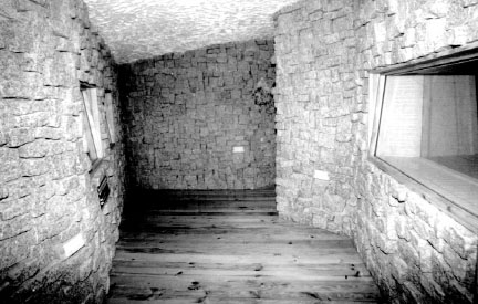
Figure 5.5 Regiestudio, Amadora, Portugal (1992)
The reduction in the spread of reflective energy renders the clearly defined reflexions and resonances that do exist to be more readily noticeable, even though the total energy which they contain is a lower proportion than that of the Planta Sonica room. Dependent upon instrument and microphone position, such rooms as the one being discussed here can have either more or less predominant character than rooms of the Planta Sonica type. The more diffusive room does not produce the same haunting wail of bagpipes, but can produce some very powerful sounds from congas, and rich enhancement of saxophones or woodwind. These two types of rooms are not really interchangeable; they are sonically very different.
5.5.2 Bright rooms
Let us now move on to consider the Regiestudio room (see Fig. 5.5) in more detail. This is a room with a total surface area of about 60 m2, about 4 m2 of which are non-parallel glass surfaces. There is also 2 m2 of flat, wood-panelled door, and around 8–10 m2 each of wooden floor and sloping, highly irregular, plastered ceiling. The remaining surfaces of the walls, which form the majority of the surface of the room, are of small granite blocks, each having a face area of 80 to 100 cm2. The cement has been deeply cut back in the gaps, producing a series of irregular cavities, but unlike the rooms in Figs 5.1 to 5.4, the ratio of the surface area of the granite to the surface area of the pits is much less; in fact only around 20% of that in the other rooms.
The effect of this is to produce far fewer specular reflexions because there are fewer flat surfaces, at least not acoustically so, until much lower frequencies. Any wave striking the wall surface will be reflected differently from the stones and pits, but let us consider the case of what happens at 500 Hz, where the wavelength is around 60 cm. If the pits average 8 cm in depth, then a reflexion travelling from the face of the stones will travel about 16 cm less than when entering and being reflected from the back of a pit. This will create about a quarter-wavelength phase shift on a single bounce, and the irregular shape of the stones and pits will tend to scatter the wavefront as it reflects from the wall. At least down to around 500 Hz, such a room surface becomes very diffusive until specular reflexions begin again when the dimensions of the stone faces become proportionate to wavelength, say above 5 kHz. However, at these frequencies and above, the irregularity of the stone surfaces themselves begin to become diffusive, so the walls begin to scatter from around 500 Hz upwards. There will also be a considerable degree of diffraction from the edges of the stone blocks, which will also add to the diffusion.
The Regiestudio room is very bright, emphasising well the harmonics of plucked string instruments, and adding richness to flutes and woodwind. Somewhat surprisingly perhaps, the reverberation time is much shorter than one would tend to expect from looking at the photograph. In this type of room, which is also very small, the energy passes rapidly from surface to surface. As the surfaces are so diffusive, the scattering of the modal energy is very wide. The speed of sound is dependent on temperature, and as almost all recording studios will be kept at relatively similar working temperatures, the speed of sound can be considered to be the same in all of them. Thus in a room such as this, the number of times that a sound wave will strike a wall surface on its travels around a room are many times greater than would be the case in, for example, the Blackwing room (Fig. 5.2). Each impact with a wall surface, especially at a near grazing angle as opposed to a 90° impact, will rob energy from the reflected wave, either by absorption or transmission, or by the energy losses due to the interaction of the diffusive elements. Consequently, in two rooms of any given surface material and construction, the small room will have the lower reverberation time because more surface contacts will take place in any given period of time. They will also have a higher initial reflexion density. The Regiestudio room produces a brightness and thickness to the recorded sound, but it falls off within about one second.
The Shambles room (see Fig. 5.6) shows a further variation on the theme, and is a room with a character somewhere between the ones shown in Figs 5.3 to 5.5. It is the only recording space of a small studio, so has to be slightly more flexible than the ‘specific’ rooms shown in the other photographs. When empty, it has a reverberation time of just over 2 seconds, but this can readily be reduced by the insertion of lightweight absorbent ‘pillars’ containing a fibrous filling, especially when they are positioned some way out from the corners. As we discussed in Chapter 2, fibrous absorbers are velocity dependent, so should not be placed too near to a reflective surface or their effect will be reduced.
From the descriptions of the rooms shown in Figs 5.1 to 5.6, it can be appreciated that the cutting back of the cement to form pits between the stone blocks both increases the diffusion and lowers the decay time. Figures 5.7 and 5.8 will help to show the mechanisms which create these effects. Figure 5.7 shows the way in which the reflexion paths differ from the front of the blocks and the back of the pits. It can also be seen that for angles of incidence other than 90° the disruptive effect will be greater as the pathlength differences increase. The frequency dependence of the effect of the irregularities is shown in Fig. 5.8. At 400 Hz, there is little difference in the interference patterns created when a plane wave strikes either the flat surface or the irregular surface at a 90° incidence angle. At 1600 Hz, however, the reflected wave is well broken by the 10 cm depth of surface irregularity. It can also be seen that the energy in the pattern reduces significantly more rapidly further away from the wall, which is a result of the diffusive effects.

Figure 5.6 Shambles, Marlow, England (1989)

Figure 5.7 Effect of incidence angle on the reflexions from the pits and blocks. From a nominal depth of cavity of 5 cm, incident wave A, when it reflects from the back of the pits, will travel about 10 cm further before returning to the room, as compared to when it reflects from the face of the blocks. Incident wave B, striking at a shallower angle, will show an even greater pathlength difference between its reflexions from the back of the pits and its reflexions from the faces of the blocks

Figure 5.8 Effect of surface irregularities on reflexion patterns. Figures (a) and (b) show the interference patterns of 400 Hz and 1600 Hz plane waves when reflecting from a flat surface. Figures (c) and (d) are again 400 Hz and 1600 Hz plane waves, but this time the interference fields are those produced by relexions from an irregular surface, such as a rough stone wall. In (c) the 400 Hz pattern is little changed from (a), but at higher frequencies, as shown in (d), where the size of the irregularities becomes significant in proportion to the wavelength, the reflexion pattern becomes fragmented, and loses energy more rapidly after reflexion
In normal situations, the effect is even more pronounced than that shown in Fig. 5.8 because the rooms which employ such surfaces usually have non-parallel surfaces. This tends to cause more of the sound waves to strike the wall surfaces at angles of incidence other than 90°, where the pathlength differences caused by the irregularities will be greater. The two primary effects of this are that the description of the interference field will extend to lower frequencies, and the energy losses after reflexion and diffraction will be greater.
In Section 2.4.1, we were looking at the question ‘What is parallel?’, and saw that the degree to which a pair of surfaces were acoustically parallel was very frequency dependent. Somewhat similarly, Fig. 5.8 shows the highly frequency-dependent nature of the effect of surface irregularities. At 1600 Hz, the effect of the surface irregularities can clearly be seen (and heard). At 400 Hz, the effect of the surface irregularities is only minimal in comparison to the interference pattern produced by an absolutely flat wall. Down at 50 Hz, the effect of the surface irregularities such as those shown in Figs 5.7 and 5.8 would be non-existent. So, in acoustical terms, a surface which can be highly non-uniform at 1600 Hz can be seen to be absolutely regular at 50 Hz.
5.6 Low frequency considerations
As discussed earlier in reference to the large room at Blackwing (Fig. 5.2) all 24 m2 of the ceiling was used as a low frequency absorber. Yet, even with this amount of absorption, the low frequency reverberation time was still much greater than that of the other rooms mentioned. Without such an absorber, the Blackwing room would have produced a build-up of low frequency energy which would have muddied all the recordings, and much definition would have been lost. No such absorption was needed in the Regiestudio room (Fig. 5.5), as such low frequency build-up cannot develop in rooms of such small dimensions because the modal pathlengths are too short to support long wavelength resonances. We shall consider this point further in the following section.
Figure 5.8 shows the way in which the reverberant characters of rooms are controlled by the different acoustical properties of their dimensions and surfaces. At the high frequencies, the room response is generally controlled by the relationship of specular reflexions to absorption. Effectively, here, the sound can be considered to travel in rays, like beams of light. In the mid-frequency band, control is mainly down to the diffusion and diffraction created by the irregularities and edges of the surfaces. At the upper-low and lower-mid frequencies, the room response is mainly that which can be reinforced by modal energy. This region is usually dealt with in terms of normal wave acoustics. As the room size reduces, it tends to produce a greater spacing of modal frequencies, and hence the energy is concentrated in more clearly defined frequency bands which leads to a more ‘coloured’ or resonant sound characteristic. However, as the room dimensions are reduced, the lowest modal frequencies which can be supported are driven upwards, so excessive low frequency build-up becomes less likely.
Small rooms tend to sound ‘boxy’ because the more readily defined modal energy is in a higher frequency range, reminiscent of the sound character of a large box, hence the ‘boxy’ sound. The modally controlled frequency region is bounded in its upper range by a limit known as the large-room frequency1, and at its lower range by a region known as the pressure zone. The pressure zone can be thought of as a frequency region in which the room is too small to be able to support modal resonances, and is discussed further in Chapter 7. In Fig. 5.9(a), a sound wave can be represented by a line crossing the room. This is a snapshot in time, and shows the positions of high and low pressure for that instant. Another snapshot taken a few moments later would show the peaks and troughs uniformly shifted in the direction of travel. At resonance, however, the interference pattern of the direct and reflected waves becomes fixed in space. A resonance occurs when the distance between two opposing, reflective surfaces bears an exact relationship to the wavelength of the resonant frequency. The modal pathway tends to trap the energy, with the peaks and troughs of the direct and reflected waves exactly coinciding with each other. The energy build-up in such circumstances can be very great. The effect is analogous to a child on a swing. If the energy input to the swing (a push) is timed to coincide with the peak of its travel, then the swing can oscillate strongly to and fro with what appear to be only minimal inputs of applied force. (See Fig. 5.9(b).)
Below these frequencies however, it can be seen from Fig. 5.9(c) that when wavelengths become sufficiently long, there are no noticeable alternate regions of the room with above and below average pressure, but rather the whole volume of the room is simultaneously either rising or falling in pressure. The room response is thus unable to boost the initial sound wave by adding any resonant energy, because it cannot provide any resonant pathways, and the sound thus decays rapidly. This is the reason why the low frequency reverberation response of rooms falls rapidly as room size reduces. Conversely, in large halls, where the pressure zone frequency is in the infrasonic region, even the lowest audible frequencies can be reinforced by modal energy. These frequencies are notoriously difficult to absorb, and are not significantly lost through doors or windows unless these are proportional to their wavelengths. They also refuse to be much thrown from their paths by obstructions, unless these obstructions are of sizes in the region of a quarter of a wavelength of the frequencies in question. In smaller rooms, however, with the rise in the pressure zone frequency, added to the increased losses due to the greater number of wall strikes per unit of time, it is therefore little wonder that the low frequency reverberation time tends to fall off more rapidly.
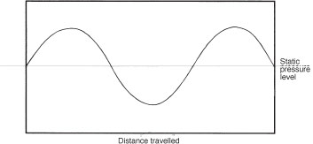
(a) A wave traversing a room will produce areas of high and low pressure which correspond to the compression and rarefaction half-cycles of the wave. Upon striking the opposing wall, it will reflect back, and if the pathlength is an integral multiple of the wavelength, the returning reflexions will be exactly in phase with the drive signal
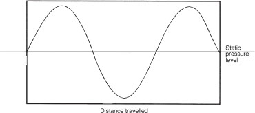
(b) As the drive signal continues, it will add in-phase energy to the resonant energy, which will build up the total energy in the resonant mode. This is similar to the effect of adding energy to (pushing) a child on a swing at the right moment, when the arc of swing can be made to increase
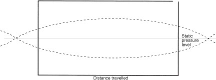
(c) Where the wavelength is longer than twice the size of the room, the whole room will be rising or falling in pressure, more or less simultaneously. This is the pressure zone condition, where alternate regions of high and low pressure are not evident
The rooms depicted in Figs 5.2 to 5.6 all have very different sonic characteristics which are derived from their physical sizes, shapes, and the nature of the arrangement of their surface materials. This is despite the fact that, except for their floor surfaces, they are basically all constructed from the same materials. In these cases, the floor material was of relatively little overall significance, although stone floors, perhaps, would add just a little extra brightness.
Rooms such as the ones described here, as with all live rooms, take some time to get to know, but once known they can be very acoustically productive. They also take a great deal of experience to design and construct. Bad ones can be really useless, or of such restricted use that they are more of a liability than an asset. There is no current hope of computer modelling these rooms, partly because the complexities of the interactions are enormous, and secondly because the influence of complex room shapes on the acoustical virtues of the subjective perception are not yet sufficiently understood to programme them into a computer. The influence of the great variety of equipment and people who may ‘invade’ the acoustic space is also beyond current modelling capability. However, for engineers wishing to record in such rooms, hopefully this chapter will have provided enough insight to make the process more productive.
Note
1 The large-room frequency, bounding the frequency region dominated by normal modal energy, and an upper frequency range which is mainly diffusion/diffraction controlled, can be estimated from the simple equation given by Schroeder:
