
Vocal rooms
When listening to recorded music, and especially on headphones, one frequently becomes aware of the sound character of the room in which the vocals were recorded. In itself, this should not be a problem, unless the room sound is ‘boxy’ or inappropriate to the song or the rest of the instrumentation. Unfortunately though, this is all too often the case, as the vocals have either been recorded in a small ‘vocal booth’ to achieve the desired separation from the other instruments, or they were recorded in a small room, perhaps because of convenience. The reason could also possibly have been because no large or neutral rooms were available. What is also unfortunate is that far too many control rooms, and/or monitor systems, are insufficiently neutral in themselves to allow the recording staff to notice the subtleties of the vocal room acoustics. This is especially the case in many multimedia or ‘project’ studios, where due attention to control room monitoring conditions has often been sadly lacking. Vocal room acoustics often have decay times which are less than those of most control rooms, hence the sound of the recorded room becomes lost in the monitoring acoustics of the control room. In other cases, the staff of a studio can become so used to the sound of a vocal room, that they no longer hear it in the background of their recordings. The problem is perhaps now greater than it used to be, as the lower noise floors of digital recording systems have rendered audible, in the home, sounds which would in earlier years have been lost in the background noise.
Where neutrality is required, vocals are usually best performed in the middle of large rooms, where there are few early reflexions. If floor reflexions are a problem, then rugs can always be provided for the vocalists to stand on, and this also helps to reduce the pick-up of the sound of any foot movements. However, most of the vocal energy usually tends not to be directed towards the floor, and so very little returns to cause problems. What is more, the selected microphone patterns are usually either cardioid or figure-of-eight, and hence naturally tend to ignore the floor reflexions.
Purpose-designed vocal rooms usually need to be as neutral as possible, unless the acoustic liveliness of a room is being used for effect. The problem with using live rooms for vocals is that, usually, the nature of the room ambience that is considered good for instruments is not an ambience that does much for voices. In large rooms, the space around the microphone is usually conspicuous by the absence of any early reflexions which can colour the sound, but in small rooms, this is not so easily achieved. As general neutrality is difficult to achieve in small rooms, and especially so in very small rooms of the size commonly associated with vocal rooms, then in circumstances where no large room is available it is perhaps better for vocal recordings to be made without any room ambience whatsoever, except perhaps for the reflexions from the floor and a window. With the use of cardioid or figure-of-eight microphones, they can usually be positioned so as to minimise the pick-up of any of these floor or window reflexions. A further difference between the recording of vocals, and the recording of many other instruments, is that there is an intelligibility factor to be considered. Many ‘vocal gymnastics’ would be rendered unintelligible in rooms where insufficient ‘space’ existed around the vocal sound before the reflexions returned to the microphone.
Due to the general persistence of the energy in low frequency room modes, simple attempts at absorption by the placing of acoustically absorbent tiles on the walls and ceiling will not suffice. These will tend to absorb the higher frequencies, but leave the lower-mid and low frequency modes largely untouched. This will produce a room with a heavily coloured ambience, which will lack life and add a thickness to the sound, robbing it of much clarity. Rolling out the offending frequencies by equalisation will take the lower frequencies out of the unwanted ambience, but it will also take them from the direct sound of the voice. In turn, this will disturb the natural harmonic structure, and will tend to remove much of its power and body. As discussed in Chapter 2, to make a very small, musically neutral room is virtually impossible, so, in the vast majority of cases, the only thing to do with a small vocal room is to absorb everything, and then provide a few discrete reflexions.
If we make the room too dead, the vocalists, on entering the room, may find it uncomfortable. In almost all cases, the vocalists will wear headphones when recording, but nonetheless their initial impressions when entering the room can have a lasting impression. They should never be allowed to feel uncomfortable, even if only for the few seconds between entering the room and putting on the headphones, as it is remarkable just how these few seconds can leave the vocalists unsure of their vocal sounds. Illogical it may well be, but artistic performances tend to be fragile things, and anything which runs the risk of introducing any extra insecurity into musicians is to be avoided. Fortunately, a hard floor and a window, or glass door, can provide sufficient reflective life to avoid the vocalists experiencing an anechoic chamber effect when they enter the room, and this is usually achievable without creating a boxy character.
Figure 7.1 shows a layout for a vocal room which occupies only about 9 m2 of floor area and 3 m of height. It assumes a ‘worst case’ structural shell of what is more or less a 3 m cube. We will presume that one wall adjoins a control room, and that the other surfaces are concrete. In many cases, vocal rooms are not only used for singing, but can also be used for voice-overs or dialogue replacement. In these cases, there would be no music to mask any extraneous noises, so the room should be well isolated. In the case of Fig. 7.1, which is based on the design of a very successful room, the whole structural shell was first lined with a 6 cm layer of reconstituted polyurethane foam of 80 kg/m3 density, except for the floor, where a 3 cm layer of a 120 kg/m3 variety is used.

(a) Plan
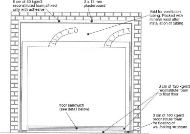
(b) Elevation

(c) Detail of floor sandwich, laid on top of reconstituted foam
The reason for the higher-density foam for the floor is because of its greater resistance to flexure under load. A thicker, lower-density foam would provide equal isolation, but if a heavy amplifier were to be placed in one corner, the floor would be less stable than if the construction method shown in Fig. 7.1 was used. Figure 7.2 shows the effect of uneven floor loading when using lower density foam with this type of separately floated floor. Figure 7.3 shows an alternative construction method, where the walls are mounted on the floated floor. In this case, if a greater thickness of low-density foam is used, the weight of the walls and ceiling will bear down on the edges of the floor, locally compressing the foam and creating a ‘crown’ in the middle. There are pros and cons to each method of construction. The first method completely decouples the walls from any impact noise directly impinging on the floor, such as if the room is being used for a bass drum, or bass guitar amplifier, when this method yields better sound isolation. The second method imparts higher damping on the whole floor, and thus reduces any resonances that may exist. Incidentally, vocal rooms of the type being described here do tend to be excellent for the recording of bass guitar amplifiers, especially if a sound with tight impact is being sought.
7.2.1 Isolating materials – density vs thickness
As for the relative isolation of thicker, low-density foam or thinner high-density foam, then for any given mass, the former is usually better. In general, barring any extra production processes that need to be paid for, one tends with most materials to pay for mass. Prices per kilogram are usually roughly equal. If we were to use a material such as mineral wool, then at 125 Hz, a thickness of 1 unit (above a given minimum) could have an absorption coefficient of say 0.07, yet a thickness of four units, for a material of similar density, an absorption coefficient of 0.38, which is over 500% greater. The absorption more or less goes up in direct proportion to the thickness. On the other hand, if we have a given thickness of mineral wool having one density unit, and another having the same thickness but four times the density, our absorption coefficient of 0.07 in the first instance would rise to only about 0.1 in the case of the same thickness but four times the density, which is an increase of less than 50%in effectiveness.
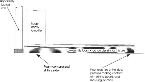
Figure 7.2 Effect of uneven floor loading on low-density float material

Figure 7.3 Crown effect
Weight for weight, and hence in rough terms, cost for cost, adding four layers of the lower density material, and allowing it to occupy four times the volume of one layer, would produce over ten times the absorption at 125 Hz than would compressing the four layers into the space of one, i.e. quadrupling the density. Table 7.1 shows some typical figures for different thicknesses and densities of a mineral wool material at different frequencies. Note how at higher mid-frequencies, above a certain minimum thickness, neither increasing the density nor the thickness has much effect.
7.2.2 Speed of sound in gases
In fact, whilst we are dealing with comparative tables, let us look at some of the mechanisms responsible for the effects shown in Table 7.1. Newton originally calculated the speed of sound in air from purely theoretical calculations involving its elasticity and density. He calculated it to be 279 metres per second at 0°C, but later physical experiments showed this figure to be low, and that the true speed was around 332 m/sec. There was conjecture that sound propagation only took time to pass through the spaces between the air particles, and that only the ‘solid’ particles transmitted the effect instantly. Newton rejected this, but then himself proposed that whilst the sound took a finite time to travel through the particles, the particles themselves did not occupy the entire space in which they existed, and that it was this fact which accounted for the difference. This idea also failed to be convincing. The difference continued to mystify people, until Peire Simon, the Marquis de Laplace, applied what is now known as Laplace’s Correction.
Table 7.1 Effect of thickness and density on acoustic absorption

It is now common knowledge that air heats when it is compressed, and cools when it is rarefied. As a sound wave travels through air, it does so in a succession of compressions and rarefactions. As mentioned earlier, Newton’s calculations were based on the elasticity and density of the air. Elasticity is the ability to resist a bending force and to ‘push back’ against it, and the speed of sound through a material is partially dependent upon its elasticity. As the compressive portion of a sound wave compresses the air, it increases its elasticity in two ways; firstly by increasing its density, and secondly by the heat which the compression generates. Where Newton had gone wrong was in the omission of the temperature changes from his calculations: he had only taken into account the elasticity increase from the density change. Perhaps this was due to the fact that there is no average temperature change as a sound wave passes through a body of air. However, locally, there are temperature changes in equal and opposite directions on each compression and rarefaction half-cycle. It is tempting to deduce that the temperature increases and decreases would cancel each other out, which is perhaps exactly what Newton did, but they do not.
As air is compressed, its volume is reduced, and on rarefaction, its volume expands. The internal force which resists these changes in volume is its elasticity. If a tube containing air is sealed at one end and fitted with an air-tight plunger towards the other end, then as the plunger is pushed and pulled, the air will compress and expand. When the force on the plunger is released, it will spring back to its resting position. If the tube was then filled with a gas of higher elasticity, the force needing to be applied to the plunger for the same volume changes would be greater, as the higher elasticity would be more able to resist the changes.
It is possible to visualise the transmission of sound through air in a manner similar to that shown in Fig. 7.4. In this figure, a series of ball-bearings are seen contained in a tube, and are separated by coil springs. If the springs are quite weak, then an impact applied to the left-hand side of ball A will pass to B, and on to C, and so forth, but there will be a noticeable delay in the transmission of energy from one ball to the next. The wave will clearly be seen to pass along the tube. Now let us assume that we apply heat to the springs, and the effect of the heat makes them much stiffer. Another impact applied to ball A will again pass down the tube, but with stiffer springs, the wave will travel more rapidly. In fact, at the extreme condition of almost rigid springs, the passage of the impact from ball to ball would be more or less instantaneous, as the ball/spring combination would behave similarly to a solid rod. The speed of the transmission of the force through the system can therefore be seen to be proportional to the stiffness of its springs. Effectively, in air, the particles can be thought of as balls being connected by springs, and that the elasticity of the air is a function of the strength of these ‘springs’. The force on one air particle thus compresses the spring, heating it up, and hence increasing the elastic force which acts on the next particle. The heating effect caused by the compression thus serves to augment the elasticity of the gas, and hence the speed with which sound will propagate through it.
In the process of rarefaction, if we consider our tube to be of ball-bearings once again, and if the balls are securely attached to the springs, then a rarefaction will pull on ball A, which will in turn pull on ball B, and on to the other balls in turn. At rest, the elastic force on ball B holds it in position, because the springs A–B and B–C are in equilibrium. By pulling ball A away from ball B, the elastic force on B is reduced on the side nearest to A, and thus the greater force from spring B–C will begin to force B towards A, until equilibrium is restored. As B begins to travel towards A, the force B–C will become less, so in turn the extra force D–C will begin to push on C, which will begin to move towards B. The wave of energy will propagate along the tube until all the balls are equally spaced once again, but all shifted slightly further in the direction of the pulling force. This is where, somewhat surprisingly, we find that the cold of rarefaction serves not to cancel the heat of compression but to work in concert with it. Hopefully, Fig 7.5 will help to show the concept in a more graphic form.
In rarefaction, the density of the A–B ‘spring’ is thus reduced, so the force on the C side of B will be greater than on the A side. The cooling produced by the rarefaction will then reduce the elasticity still further (weakening the spring) and thus will act in the same direction as the density reduction, making the A–B force even less. This will mean a greater differential between the A–B and B–C forces, so B will be pushed away from C with greater force than that of the rarefaction density change alone.

Figure 7.4 Energy transmission via masses and springs. Four balls (A, B, C and D) are separated by springs in a glass tube. The system is shown in equilibrium, with no force applied, and the springs in a relaxed state

Figure 7.5 Application of force to system shown in Fig. 7.4. If a force is applied to ball A it will transmit the energy to B via the spring. B will then, via the B–C spring, transmit the energy to C, and so forth, until the whole chain of balls and springs is moved in the direction of the applied force. The speed with which the force will pass along the line is proportional to the stiffness of the springs (the elasticity of the coupling). In the above example, the spring between A and B is seen to be compressed. The force on B is thus no longer in equilibrium, so B will move towards C, transferring some of the energy in spring A–B to compress spring B–C until springs A–B and B–C are in equal compression, when B will tend to come to rest. In this state, spring B–C will be partially compressed. C will thus have more compression in the B–C spring than in the C–D spring, so it will move in the direction of D. Due to the applied force and the momentum in the moving balls, the system will oscillate at its natural frequency until it finally comes to rest, when the applied energy has been expended, shifted to the right
Hopefully, it can be seen from the above, rather long-winded discussion that the heat of compression and the cold of rarefaction both work in the same direction as the density changes, and hence both increase the effect. The additional help caused by the elasticity changes due to heat is the reason for the speed of sound in air being greater than that first calculated by Newton from the elasticity and density alone. The heat of compression and the cold of rarefaction do not cancel each other out but work together to increase the speed of sound through any medium. Once this was realised, experiments were performed to test the ability of air to radiate heat, which was subsequently found to be very poor. This explained why the temperature changes remained in their respective compression and rarefaction cycles, and did not affect each other.
Why we have been discussing all this history following our table of absorption coefficients of mineral wool at various densities and thicknesses is that the above fact is one of the mechanisms at work. In loosely packed fibrous material, such as mineral wool, glass fibre, bonded acetate fibre or Dacron (Dralon) fibre, the fibres can act to conduct the heat away from the compression waves, and release it into the rarefaction waves. This removes a great deal of the heat changes available for the augmentation of the elasticity changes, and hence tends to reduce the energy available for sound propagation. It changes the propagation from adiabatic (the alternate heating and cooling) to isothermal (constant temperature) which slows down the speed of sound. It was the isothermal state that Newton had calculated, but it was the adiabatic state that was the normal situation. Due to the above effects, a loudspeaker cabinet which is optimally filled with fibrous absorbent material appears to be acoustically bigger than it is physically, as the speed of sound within the box is slowed down by the more isothermal nature of the propagation through the absorbent fibres.
Incidentally, Laplace’s Correction, as referred to earlier, is quite easy to explain. If we place a known volume of air at 0°C, and at a known pressure, into a pressure vessel, then heat it by 1°C, the air cannot expand, so the pressure will rise. If we then place the same volume of air also at 0°C in a vessel of the same volume, but fit it with a plunger which can be forced outwards as we heat the air to 1°C, the pressure can be allowed to remain constant, by allowing the volume to change. In each case, we heat the same mass of air by 1°C, yet the heat necessary to do so in each case is quite different. One is called the specific heat of air at constant volume, and the other, the specific heat of air at constant pressure. In fact, the latter (Cp) divided by the former (Cv) gives an answer of 1.42, and it was the square root of this number by which Laplace multiplied Newton’s original calculation in order to correct his calculated speed of sound in air to the observed speed. The reason for the difference between the two specific heats is that in the second instance (Cp) extra heat is consumed in the work of expanding the gas.
7.2.3 Other properties of fibrous materials
Still on the subject of the absorbent properties of our fibrous materials, there are other forces at work besides their ability to convert the sound propagation in air from adiabatic to isothermal. There is a factor known as tortuosity, which describes the obstruction placed in the way of the air particles in forcing them to negotiate their way round the medium. The tortuosity, in increasing the pathlength of the sound which travels through the fibres, also increases the viscous losses which the air encounters as the sound waves try to find their way through the small passageways available for their propagation. In certain conditions, air can be quite a sticky fluid. There are also internal losses as the vibrations of the air cause the fibres to vibrate, and in order to bend, they must consume energy. Frictional losses are also present as vibrating fibres rub against each other. Energy is required for all of this motion of the fibres, and by these means, acoustic energy becomes transformed into heat energy.
Because the above losses are proportional to the speed with which a particle of vibrating air tries to pass through the material, their absorption coefficient is greater when the particle velocity is higher. If we consider a sound wave, arriving at a wall, the wall will stop its progress, and reflect it back. At this point of reversal of direction, the pressure will be great, but the velocity will be zero. The same consideration applies to any ball which bounces from a wall. The absorbent effect of fibrous materials is thus greatest when they are placed some distance away from a wall, and if any one frequency is of special interest, then a distance of a quarter of its wavelength would be an optimal spacing away from a wall for the most effective absorption by a fibrous material. Conversely, membrane absorbers are dependent upon force for their effectiveness, so should be located near to the point of maximum pressure (i.e. close to a wall) if absorption is to be maximised. The absorption mechanisms are thus very different.
7.2.4 Absorption coefficients
Before leaving the subject of fibres and returning to our vocal room, let us consider the concept of sound absorption coefficients, and clear up any doubts about absorption and isolation. Acoustic absorption is the property which a material possesses of allowing sound to enter and not be reflected back. In this sense, absorption coefficient refers to sound both internally absorbed, and also that which is allowed to pass through. A large, open window is therefore an excellent absorber, as only minuscule amounts of any sound which reaches it will be reflected back from the impedance change caused by the change in cross-sectional area of the spaces on each side of it. A solid brick wall is a very poor absorber as it tends to reflect back most of the sound energy which strikes it.
Now let us put some practical figures on some different materials. A 2.5 cm slab of a medium-density fibreglass can absorb about 80%of the mid and high frequency sound which strikes it. An open window will absorb in excess of 99%of the sound energy which is allowed to pass through it, and a brick wall, made from 12 cm solid bricks, will allow about 3%of the sound to enter or pass through. Looked at another way, the fibreglass will reflect 20%of the sound energy back into the room, the open window will reflect less than 1%, and the brick wall 97%. If we now look at the same materials in terms of sound isolation, the situations are very different. An open window will provide almost no isolation, except a small amount at frequencies with wavelengths longer than the largest dimension of the opening. Our slab of 2.5 cm fibreglass will provide around 3 dB of isolation (although at low frequencies almost nothing), but our brick wall will provide over 40 dB of isolation. Thus in these cases, absorption coefficient and sound isolation properties are unrelated. In fact, in the examples quoted, they run in reverse order. Absorption and isolation properties should not be confused.
7.3 Application to a practical room
Let us look in more detail at the vocal room in Fig. 7.1. As already stated at the beginning of Section 7.2, the walls and ceiling are covered with 6 cm reconstituted polyurethane foam, attached by contact adhesive. In turn, the foam is then lined with a layer (or two if needed) of 13 mm plasterboard. This type of combination, mass/spring/mass (plasterboard/foam/wall), is ideal here as it serves two purposes. Firstly, it provides a good degree of broadband sound isolation. Secondly, it also provides a good degree of low frequency sound absorption. It therefore acts like a reasonably good combination of our open window and brick wall from the previous paragraph. However, this system achieves by internal absorption what the wall and window do by reflexion and transmission. What is more, if the space between the inner, floated room structure and the foam/plasterboard isolation treatment is lined with a fibrous, high-density material, we can then incorporate the properties of fibrous absorption to prevent any resonances from developing in the gap. We can thus combine high absorption, high isolation (low transmission) and low reflexion, all from the same composite lining. This is important because in our vocal room we do not have sufficient space for large, conventional, wideband absorber systems.
The vocal room ‘box’ is constructed on the higher-density foam which is first placed on the floor. The walls and ceiling structures are similar in nature to the ‘neutralising’ acoustic shell described in Chapter 2. This time, however, let us consider the progress of a sound wave as it leaves the mouth of a vocalist, and arrives at the room boundaries as shown in Fig. 7.1. Remember, we want this room to be sufficiently dead to give no recognisable sound of its own to the recording, but to have just enough life to prevent the room from making the vocalist feel uncomfortable when entering it.
7.3.1 The journey of the sound waves
The sound waves expand from the mouth of the vocalist in a reasonably directional manner. Except at the lowest frequencies, this fact becomes self-evident upon working in these rooms. Another person becomes remarkably quieter if he or she should turn away from you, unless that is, they turn to face the reflective glass doors, or the floor. In most cases, the vocalist will be facing glass doors or windows, as visual contact with the control room is usually required for operational purposes. The sound will leave the mouth and strike the glass, which will reflect a good 90%of the energy back into the room with a very wide angle of dispersion. Without headphones, the vocalist will hear this, plus any reflexions from the floor, which may either be direct or via the window. These reflexions will help to alleviate any sense of being an oppresively dead room.
Energy reflecting back from the glass will strike the two side walls and the ceiling with an oblique angle of incidence. Only the wall opposite the glass will receive any sound at perpendicular incidence. The oblique arrival of sound at the face of an absorber will usually cause a much greater loss of energy, as it must pass through the absorbent material in a diagonal manner, and thus effectively travels through a thicker section of material (see Fig. 7.6). Any sound reflecting from the window and the floor will automatically then pass into the walls at oblique angles. If a cardioid microphone is placed between the vocalist and the window, and faces the vocalist, it is only capable of receiving sound directly from the vocalist’s mouth, plus, perhaps, a minute amount of the floor reflexions.
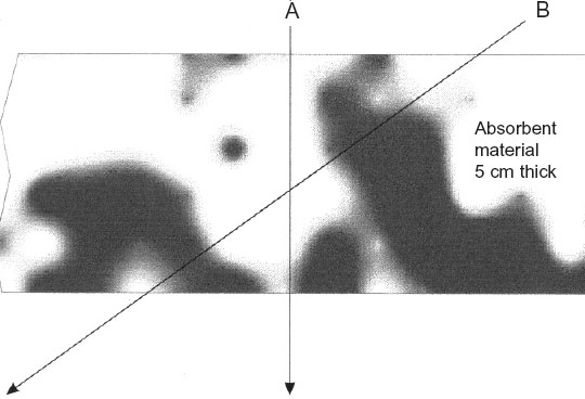
Figure 7.6 Effect of angle of incidence on absorption. An incident wave A, striking the absorbent material at 90° would pass through the 5 cm thickness of the absorbent material. Incident wave B, striking at a shallow angle, would pass through approximately 10 cm of the absorbent material. For material of random texture, the absorbent effect is correspondingly increased in proportion to the extra distance travelled through the material. It should be noted, however, that for certain types of material with a pronounced directionality of fibres or pores, the above case may not apply
The sound which passes into the first layer of felt, behind the decorative fabric surface, will be partially absorbed, but some will continue through to reach the deadsheet backing. At medium and high frequencies, the deadsheet is reasonably reflective, but any high frequencies reflected from it, even at 90° incidences, will still have to pass once again through the felt in order to re-enter the room. For wavelengths in the order of 8 cm (4 kHz), 2 cm of fibrous absorption will be highly effective, as the internal passage of sound through felt at relatively short wavelengths is complex. If only 10%of mid and high frequencies were reflected from the surface of this vocal room on the first contact with a wall, then the second strike would only reflect 10%of that 10%. By the third bounce, which in such a small room may only take 15 or 20 ms, the energy remaining in the reflexions would only be thousandths (10%of 10%of 10%) of that leaving the vocalist’s mouth. It would thus be 30 dB down within the first 20 ms, and 60 dB down in considerably less than 50 ms.
At low frequencies, such as those produced if a bass guitar amplifier were to be placed within the room, the mechanisms are very different. The low frequency sounds would propagate omnidirectionally and would possess much more penetrative power than the high frequencies, due both to the much greater acoustic powers involved, and because of the wavelengths being very long compared to the wall thicknesses. The first internal lining of the rooms (behind the decorative fabric that is) is in this instance a kinetic barrier material (deadsheet) covered in a 2 cm layer of cotton-waste felt. The composite weighs 5 kg/m2 and comes in rolls, 5 m 1 m, and this is nailed to the stud framework of the room, felt-side to the room. Behind this barrier is an air cavity of 7.5 cm, containing a curtain of the same cotton-waste felt material, hung from the top, and cut carefully to fill completely the cross-section of the gap. On the other side of the stud frame is a double layer of 13 mm plasterboard, with a layer of 5 or 10 kg/m2 deadsheet sandwiched in between.
All of the above layers are diaphragmatic; they are free to vibrate, but they are also all highly damped. The room, to the low frequencies at least, presents itself as a large, limp bag. When the sound waves strike the kinetic barrier, it is somewhat like the effect of a boxer striking a heavy sand bag: the room gives, absorbing much of the energy and converting it into heat. Effectively, the inner wall lining gets pushed and pulled around by the compression and rarefaction half-cycles of the sound waves, but its weight and internal viscous losses are such that it is almost incapable of springing back. Linings of this type have low elasticity, they are more or less inert, which is why such materials are known as deadsheets. In a similar way, you can give an almighty clout to a bell made from lead, but you will not get much ring from it. The lead will yield to the blow, and its high internal damping will absorb the impact energy. Its weight will then ensure that it does not move much, and hence if it can barely move or vibrate, it will have difficulty in radiating any sound.
When the sounds vibrate the deadsheet linings of our vocal room, work is done in moving the heavy, flexible mass, and acoustic energy is turned into heat energy as a result of the damping which resists the movement. Some sound is inevitably reflected back into the room, but with room dimensions so small, in a matter of a few milliseconds the reflected energy strikes another surface, so suffers losses once again. All in all, the sound decays very rapidly, and the low frequencies, below 150 Hz or so, are effectively gone in less than 100 ms. The very low frequencies receive no support at all from modal energy, as the pressure zone in a room of such size exists up to quite high frequency.
7.3.2 The pressure zone
Modal support was discussed in Chapter 1, and pressure zone concepts were outlined in Fig. 5.9, but let us look once again at the concept in a little more detail. If less than half a wavelength can exist within the dimensions of a room, instead of waves of positive and negative pressure distributing themselves over the room, the whole room will either be rising in pressure, or falling, depending on whether it is being subjected to a positive-going or negative-going portion of a long wavelength. The frequency below which the pressure zone will exist is given by the simple formula:

In the case of our room under discussion here, the maximum room dimension is from the lower corner to the opposite upper corner, marked X and Y in Fig. 7.1(a), and is about 4 m, so the formula would give:

However, funnelling the wave into the corners with floppy walls and a diagonally placed felt layer is hardly representative of a reflective situation for a low frequency wave, so the longest side-to-side dimension would be more relevant. Substituting the 2.5 m side-to-side distance for the 4 m corner-to-corner distance, the formula would give a more reasonable pressure zone frequency as 67 Hz. There could therefore be no modal support in this room below 67 Hz, and the heavily damped 67 Hz mode would be the only supportable mode within the first octave or so of a bass guitar. The response can therefore be expected to be very uniform.
7.3.3 Wall losses
When this internal bag inflates and deflates, it does radiate some power outwardly, but the nature of the construction of the room is such that the air cavities created between the vertical studs and the outer and inner linings provide further damping on the inner bag. The air will tend to resist the pressure changes, as its elasticity will apply a restoring force on the inner bag. In turn, it will also exert a force on the outer composite layer of plasterboard and deadsheets. This layer is also very lossy and heavily damped. The internal particles in the plasterboard turn acoustic energy into heat by the friction of the particles rubbing together, and additional work is done by the need to move such a heavy mass. The sandwiched deadsheet forms a constrained layer, tightly trapped between two sheets of plasterboard. The constrained layer concept, shown diagrammatically in Fig. 1.5 and discussed previously in Chapter 1, effectively tries to sheer the trapped layer of viscously lossy material over its entire surface. The resistance to this sheering force is enormous, so the damping value is high, and the acoustic losses are great.
The transmission from the inner layer to the outer layers of the stud wall is partially due to the common studwork to which both surfaces are connected. This usually creates no problems as long as the inner surface is of a limp nature. Its lack of rigidity does not provide an effective acoustic coupling to the studs, and its weight, in turn, helps to damp the stud movement. The direct energy impact on the studwork itself, where the deadsheet is fixed to it, and hence where that deadsheet is effectively more rigid, is only a small proportion of the overall surface area. If the studs are 5 cm in width, and spaced on 60 cm fixing centres, then they occupy only 5 cm out of every 60 cm, or about 8%of the surface area. In addition, being of narrow section, the lower frequency waves will tend to pass round the studs. However, if every last decibel of acoustic performance is required, the slightly more complex stud arrangement as shown in Fig. 7.7 can be used. Here, the studs are double in number, but are interleaved such that the only common couplings between the two surfaces of the wall are at the top and bottom, which are in any case coupled by a common floor and ceiling. Walls of this type take up an extra 2 cm of space, but if the extra performance is needed, the space penalty is low. Thinner studs could be used if the space was critical, but they would provide less damping on the panels, and hence may negate some of the advantage gained by the separation.

Figure 7.7 Staggered stud system. The sheet layers on each side of a stud wall can be attached to independent sets of studs, connected only by the top and bottom plates C. By staggering the studs and interleaving them, only a small amount of extra space is consumed compared with that of a conventional stud wall. This system reduces greatly the area of common coupling between the two sets of sheet materials, and usually offers more isolation than the more usual system with common studs
The majority of the inter wall-surface coupling is in any case through the air cavity. The cavity in this case is lined with cotton-waste felt, which helps to increase the losses, but at very low frequencies its effect is only minimal. The losses from the air cavity coupling are great as long as the outer surface is very heavy, as it is difficult for a thing of low mass to move a more massive one. It is therefore relatively difficult for the air which is trapped in the cavity to excite the outer composite layer of heavy sheet materials. Historically, some of the first tests of this principle were carried out by experimenting with cannons in the Alps, so as this factor of acoustic coupling is quite an important aspect of our isolation systems, perhaps we should now consider it in a little more detail.
7.3.4 Transfer of sound between high and low densities
In the 19th century, two cannon were placed on the side of a mountain, one low down, but not at the foot, and the other high up. The cannon were charged with equal amounts of powder, and observers were placed not only at each cannon position, but also high up and low down on a mountainside at the opposite side of the valley. The arrangement is shown in Fig. 7.8. The cannon low down was not placed at the very bottom of the valley, so that its sound would not be unfairly reinforced by having the valley floor to push against. When the cannon were fired, the flashes and the smoke were clearly seen from all distant stations, and as the distances to the listening stations were known, the sounds of the cannon were expected to be heard after the appropriate time intervals had elapsed.
The lower cannon was fired first, and the three listeners at the distant listening stations, A, B and D, awaited its report, which duly arrived at each position at the respectively appropriate times. In each case, when the sound was heard, the listeners signalled its arrival by means of flags. The sound intensity at each station was described as best as could be done in the days before sound level meters. The sound was heard loudly by the listener low down on the opposite side of the valley, and was clearly heard by the two listeners high up on the two sides of the valley, positions A and B in Fig. 7.8. When the higher cannon was fired from position A, again the flash and the smoke was clearly seen by the distant listeners, this time at positions B, C and D. After the expected time interval had elapsed, the listener at position B signalled that the report had clearly been heard, but after more than enough time had passed for the sound to arrive at positions C and D, no signals were seen, as no sound had been heard.
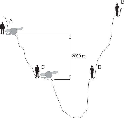
Figure 7.8 Cannon experiment. Two identical cannon are positioned at A and C, and charged with equal amounts of powder. When cannon C is fired, the observers at A, B and D will see the flash almost instantaneously. After a length of time corresponding to the local speed of sound in the air, and their distance from C, the three observers will hear the report from the cannon. When the cannon at A is fired, the observers at B, C and D will see the flash. After the appropriate time lapse, the observer at B will hear the sound, but the observers at C and D, in the denser air, may hear nothing, despite the fact that they are closer to A than is observer B
From this it was deduced that the density of the air in which the sound was produced, relative to the density of the sound in which it was heard, was responsible for the efficiency with which the sound would propagate. The explosion in the higher density air, low down in the valley, could easily cause the sound to propagate not only to the listening station D, in the same high density air, but also to the listening stations at A and B, higher up in the lower density air. However, whilst the report from the high cannon could be readily heard at listening position B, which was in the same low density air, the sound could not penetrate effectively into the higher density air at the lower listening stations, C and D. This was despite the fact that position C was closer to A than was position B, where the report was clearly heard. Furthermore, compared to the denser air at the bottom of the valley, the thinner air higher up the mountain provided the explosion of the gunpowder with less air to push against as it left the barrel of the cannon. With less air to push against, less work could be done by the explosion, and hence less work done meant less sound generated. The air pressure reduces by almost 1 millibar for every 8 metres that one rises above sea level, and if temperatures are equal, the densities will thus be proportionately reduced. In fact, given the 2000 m vertical separation between the cannons shown in Fig. 7.8, the air pressure at the upper positions, A and B, would be less than 75%of that at the lower stations, C and D.
7.3.5 The weight of air
As we are surrounded by air from the day that we are born to the day that we die, there is a tendency for many of us to take it for granted, but to the musical acoustician it is the prime medium for consideration. Without understanding its properties, the science of acoustics cannot be applied, so now that we have considered its density, perhaps we should consider its weight. In fact, the weight of air surprises many people who have not studied the subject. When a jumbo-jet flies at an altitude of 10,000 m, the inside will usually be pressurised to the equivalent of about 2000 or 2500 m. Above an equivalent pressure altitude of around 3500 m, the air is too rarefied to provide enough oxygen for human beings to breathe and remain conscious; unless, that is, one’s blood has had some time to acclimatise and change its constitution (hence high-altitude training by athletes to enrich their blood before competitions). For this reason, the pressure in the aircraft must be kept below the equivalent pressure of 3500 m, unless oxygen masks are worn. If passenger comfort only were to be considered, it would be better to pressurise the aircraft to the sea-level pressure, as ear-popping, dry skin, thirst, and other side-effects of depressurisation could be avoided, but there are two reasons why this is not done. The first reason is that by reducing the pressure inside the aircraft, the pressure differential between the inside and outside is reduced, and hence the stresses on the air-frame are reduced. It is thus not necessary to build the aircraft so strongly if they only pressurized to 2500 m, and the weight saving from a lighter air-frame allows less fuel consumption, and hence reduces the running costs and ticket prices. The second reason however, is less obvious. The difference in weight between a jumbo-jet pressurised to sea-level, and one pressurised to a pressure altitude of 2500 m, is about half a ton. Transporting that half ton around for the life of the aircraft would cost a fortune in extra fuel. When one thinks about it, a compressed air cylinder for scuba diving is considerably heavier when full than when empty, and one can fill an awful lot of compressed air cylinders from the air contained within a jumbo-jet.
I hope that the descriptions in the last few paragraphs, highlighting the very considerable presence of air as a fluid, will aid in the understanding of the effect of the air gaps between the different layers of acoustic wall structures. They are certainly not the empty spaces that they are often thought to be. If the physical properties of the air are duly taken into account in the consideration of the wall structure, they can be used to benefit, not only in the acoustic damping of the wall systems, but also by creating more losses due to both the effects of the density and the acoustic impedance changes which the air can provide.
7.4 Combined effects of losses
After this long detour into the physics and acoustical properties of air, let us return again to our room. It can now be appreciated that the acoustic energy will be severely attenuated by the compounding of the low frequency losses in the deadsheet, the damping loaded upon it by the air in the inter-stud cavities, and the mass of the plasterboard to be moved; damped by the sandwiched, heavy deadsheet. As this whole structure is set on a layer of foam of an appropriate density, it thus sits on a foam spring, surrounded on the other five sides by air springs. The radiation of what energy is left must now pass through the ‘springs’ in order to get to the plasterboard layer which covers the foam, which is in turn glued to the structural walls. Springs are reactive; that is they tend to store and release energy, rather than passing it on. The cavity in Fig. 7.1 is lined with cotton-waste felt. Any resonances which try to build up in these air cavities, particularly as lateral movement of the air, or waves travelling around the box, must effectively pass through metres of felt, which they patently cannot do. By such means, resonances in the air space are effectively prevented. One acoustic ‘short circuit’ is therefore avoided, as if the air was resonating, its ability to couple the two sides of the gap would increase greatly.
The low-density air surrounding the inner, floated, acoustic shell must then transfer its vibrational energy to the much heavier plasterboard wall linings. As with our cannon, it is difficult for a low mass of low-density material to excite a high mass of high-density material, so further transmission losses take place as the mass of the plasterboard resists the movement of the air in contact with it. The particles in the plasterboard also provide losses due to their friction, so this reduces even more the energy which can be imparted to the foam to which it is stuck, and which in turn is stuck to the wall.
The foam itself, securely bonded to the plasterboard by adhesive, strongly resists the movement of the plasterboard, so yet again, vibrational damping is provided and even more acoustic losses take place. Finally, the foam, glued to the structural wall, flexes under the force being imparted to it from the plasterboard, because its mass and stiffness are insignificant compared to those of the main structural wall which it is trying to move. The exact effect of this final loss depends mainly on the mass of the wall to which it is attached, but typically, from the inside of the finished room to the other side of a structural wall, 60 to 80 dB of isolation at 40 Hz could be expected from a structure similar to that being discussed here.
Of course, what we have been considering here on our journey through the complex wall structure are transmission losses, but we should not forget that from each layer boundary, and particularly the inner boundaries of the more massive layers, acoustic energy will be reflected back towards the room. We have four heavy layers in this structure, the deadsheet inner lining, the composite plasterboard/deadsheet sandwich on the outside of the inner box, the plasterboard which is glued to the foam, and the structural wall. We discussed earlier the progress of the reflected wave from the inner lining, but as we pass to the sandwich layer, the reflexions will be stronger due to the greater rigidity of the material. However, these reflexions cannot pass directly into the room. They must first pass through the inner deadsheet layer, which has already attenuated the incident wave by its mass, its internal viscous losses, and its poor radiating efficiency. The reflexions from the sandwich layer will also suffer similar losses as they seek to pass through on their way back into the room. What is more though, just as some energy of the incident wave is reflected back into the room from the internal lining of deadsheet, the lining will also reflect back the reflected wave into the wall structure, towards the sandwich, a portion of the energy reflected from that sandwich, so round and round we go, losing energy at all stages. The more internal losses which we can create within our multi-layered wall by using internal reflexions to trap the sound within the layers until it dissipates as heat, then the more pure absorption (i.e. not counting transmission) we will be able to achieve.
Similarly, the other heavy boundary layers on either side of our 6-cm foam, stuck to the structural wall, will also reflect energy back towards the room, but the deeper we go through our complex wall structures, the more difficult it will be for the acoustic energy to find its way back into the room. Taken as a whole, such a complex wall structure as in Fig. 7.1 deals with our internal acoustic problems and our sound isolation problems by its high overall internal absorption. The structure is progressively absorbent, in that the most reflective layers are those furthest away from the inside of the room. If we remember our open window and brick wall discussion, simple sound-absorbing materials tend to be poor isolators, and good isolators tend to be poor absorbers. In the case of our vocal room, though, we need both good absorption and isolation. The option of placing an adequate amount of a sound-absorbing material on the inside of a room, then placing a simple isolation wall outside of it, tends to use enormous amounts of space. Using such simplistic techniques in a space of 3 m3 (the same as the structural space for the room in Fig. 7.1), we would end up with a usable space only about the size of a telephone kiosk.
The multi-layered, complex structures described here are much more efficient in terms of the space which they consume. They are also a little like the energy absorbing front ends of motor cars which crumple gradually on a frontal impact, absorbing the energy of a crash stage by stage, and preventing it from doing too much damage to its occupants, or to the occupants of the car which it may have run into. Similar principles are now employed in the new, lightweight armour for battle tanks and warships, in place of the enormously heavy, steel armour-plate which was used, almost exclusively, up to the late 1960s. The similarities here should not be too surprising as, after all, energy absorption is energy absorption, whether it is absorbing the energy of car impacts, shells, or sound waves.
Well, now that we have dealt with the relatively simple surface treatments which absorb the upper-mid and the high frequencies, and we have discussed the limp bag which so effectively controls the low frequencies, all that we are left with are the low-mid frequencies. These are the modal frequencies, where resonances can develop between the faces of the room surfaces. Their waves are too long to be absorbed by the superficial layers of absorbent felt, but do not carry enough energy to punch their way through the deadsheets and composite layers. In the modal controlled region, there are two types of mode – the forced modes, which are driven by the sound source but which stop when the forcing stops, and there are the resonant modes, which can continue to ring on at their natural frequency long after the driving force has ceased. A loudspeaker, when driven by an amplifier, will vibrate at the driving frequencies, but when the drive is disconnected, and if there is little damping, the cone will continue to resonate for a short time at its natural frequencies. The mechanism in the cases of the room and the loudspeaker is similar.
The problem in terms of the decay time of the room is the resonant modes, the worst offenders of which usually develop between parallel surfaces or opposing corners. A discussion of modal patterns was given in Chapter 1. In the room of Fig. 7.1, no parallel surfaces exist, as the walls have been angled in order to use geometrical techniques to help to prevent modal reinforcement. The amount of angling shown would not be enough in a more lively room, as the lower of the lower mid-frequencies would still see them as relatively parallel in terms of their wavelength (see also Chapter 2), but in the case of a room lined with so much felt and deadsheet, the gradual, non-perpendicular impact tends to suffer much greater absorption and much less effective re-radiation than would be the case when striking similarly angled, but more reflective, surfaces.
The ceiling structure of our vocal room is similar to that shown in Fig. 2.2(b). It is vaulted with the PKB2 composite deadsheet/felt material, the felt side facing the floor. The 20-cm depth of the vaulting is sufficient to begin to take the energy out of both the direct mid-frequency waves and the ones reflected almost perfectly from the hard floor. As the wooden floor is a better reflecting surface than any of the other surfaces of the room, the design of the ceiling opposing it has to give due consideration to that fact. Above the inner ceiling is a void of about 30 cm depth. When stuffed with absorbent material, be it fibrous or off-cuts of foam, it provides good absorption of any lower mid-frequencies which may penetrate the inner linings. The ceiling void is actually there primarily for another purpose however; the passage of ventilation ducts, as one does tend to have to provide vocalists with a good supply of fresh air, delivered as smoothly and silently as possible. Nonetheless, the area provides useful space for extra absorbent material to add even further control to the room.
7.4.1 A micro-problem
In small vocal rooms, subjectively, the lower mid-frequencies tend to be the most difficult ones to suppress, but in a room such as the one which we are discussing here, the remnants of modal energy which may be detectable after making a sudden, loud ‘a’ sound, as in cat, tend to be no problem in practice. However, as I learned the hard way, these rooms are better assessed through microphones than by listening inside of them. When I completed one of my first rooms of this type, although quite a bit larger than this one and with an extra window, there was a resonance which was detectable at about 400 Hz, and which lingered for a short time after impulsive excitation of the room. In spare hours, I searched for days for ways to control the problem but it simply refused to go away. The studio finally went into use during the time that we were building a second studio for the client, but I thought it a little strange that we had heard no complaints from the recording engineers about the vocal room resonance. In fact, the only comments about vocals recorded in the room were to the effect that they were beautifully clear. So, without drawing attention to the problem, I asked to hear some of the vocal recordings made in the room, and sure enough, I could hear nothing of the problem resonance, not even with the vocal tracks soloed. The room had a sliding glass door which faced the control room, and a window in an adjacent wall for visibility through to the main studio room. Though this wall was at 90° to the wall with the doors, the window was raked back about 8° from the vertical. There was also a very small window leading to the small vocal booth of the adjacent studio, but this faced directly towards neither of the other windows. The floor was of ceramic flooring tiles. Some thing or things in this room conspired to produce the resonance, but we never found the cause: finishing the other studio was a more pressing task. We conjectured that the recordings were clean because the directionality of the microphones when pointing in the usual direction did not face the source of the problem, which was no doubt partly true.
Eventually, more out of interest than necessity, we brought in equipment to hunt for the rogue resonance, and we were all surprised to find that it was about 70 dB down on the direct sound. Apart from the life provided by the single reflexions from the windows, glass doors and the floor, all of which were ‘one shots’, there was almost nothing left in the room response except for our ‘problem’, which could perhaps have been a cavity resonance between the double-glazed windows, but we soon forgot about it. It is strange how something can be magnified in one’s imagination if one knows a problem to be there. Once I knew that this problem was not a problem in practice, I rarely noticed it again, except if I listened purposely for it. This story does go to show, though, just how effective the treatments described in this chapter can be in taking the decay problems out of a small room, yet allowing sufficient single reflexions to give a feeling of reasonable life and rendering the room pleasant to be in. We often notice this type of effect on a larger scale when putting the first acoustic treatment in buildings. It is surprising how many unpleasant sounds are exposed as the process takes effect before each one is finally eliminated. These sounds are all there in the original room sound, but many only become apparent as other room effects are removed. It is a little like peeling the skins off onions, where, as one is removed, another, smaller, different one becomes apparent. In very low decay-time rooms it is quite possible to begin going round in ever decreasing circles, trying to remove every last trace of the room’s artefacts. It takes some experience to know where to stop, and the final recorded sound quality is the ultimate arbiter.
It is customary in such rooms to provide skirting boards to protect the walls when cleaning the floor, and also shin rails, on which to mount sockets for microphone inputs and power outlets. A dado rail is normally also provided at waist height, to give people something to lean on and prevent them from falling through the fabric. If these are only 10–15 cm in height, as depicted in Fig. 2.17, the specular reflexions that they may provide, even if the surfaces are varnished wood, seem to be of no subjective consequence, as they cannot support resonances. Frequencies below around 2 kHz just pass round them as a river flows round a projecting rock. Fabrics, though, can be reflective if they are too stiff. Fabrics such as calico can be so tight when stretched on their frames that they ring like drum skins. The best fabrics to use are similar to the ones used in the neutral rooms of Chapter 2, soft ones with a relatively open weave, or ‘stretch’ type dress fabrics, such as Lycra, which are also excellent. They remain neatly taught, and spring back if anybody pokes them, yet they remain limp enough and are sufficiently open to be sonically inert. There are also a number of manufacturers now making fabrics specifically for acoustic purposes, and these are often flame retardant, or even totally non-flammable, for use in public spaces such as theatres and concert halls.
I find rooms such as these very effective for vocal performances, and also very useful for getting tight, powerful bass guitar recordings, but for other instruments they are not too inspiring. On the other hand, I know people who do like to get ‘clean’ recordings of instruments so that they have the maximum potential for processing in the post-recording stages, and for such purposes these rooms are excellent. One can also experiment with pointing the microphones at the floor or the glass doors, as some interesting effects can be achieved, but if such effects are required, it is simple to install reflective panels when needed. All in all though, for vocal rooms, these constructional techniques work extremely well.