
Neutral rooms
Historically, recording studios, and by the word ‘studios’ I mean the recording spaces as opposed to the control rooms, have been relatively neutral environments. This has been partly due to past recording studios having to cater for a wide range of recordings. Too much bias towards the needs of one specific type of music could lead to a restriction in the amount of work available for a studio, and, furthermore, it was generally held that the responsibility for the production of the sound to be recorded was within the domain of the musicians. The function of the recording studio was seen as being to record the sounds which the musicians produced, as faithfully as possible. The days of a somewhat more creative side to the recording process had not arrived.
However, contrary to what may often be expected, the ‘true’ sound of a musical instrument (that is, the sound as its designer intended it to be heard) is not that which it would make in an anechoic chamber. This is because instruments were developed in the circumstances of more reflective or reverberant surroundings, and it is frequently the combined direct and reflected sounds which constitute the ‘true’ sound, that is, the sound as its designer intended it to be heard. Concert halls have long been rated by musicians according to how well they can perform in those halls. Players of acoustic instruments need a feedback from the performing space, as frequently the sound emissions from the instruments are inadequate to give, directly to the musicians, the sensations required for optimum performance. String sections need to hear string sections, not a group of individual instruments. When they hear a section, they play as a section; when they hear separate instruments, their playing also often fails to gel into a single, homogeneous performance
Flautists seem almost always to need some reverberant help for their playing, be it natural, or fed electronically into their headphones. Woodwind players also seem to dislike too dry an ambience in their performing space. An anechoic chamber is a truly awful environment in which to play any instrument, and such an environment is not going to inspire any musician to the heights of creativity. Creativity is supremely important, as certainly as far as I am concerned, an uninspired performance is hardly worth recording.
So, if we do not mean a clinically accurate recording space when we speak of ‘neutral’ spaces, then what are we talking about? Essentially, a neutral environment is one which provides sufficient life to allow enough of the character of an instrument to be realised, but which does not overpower the instrument with the character of the room itself. This means a smoothly sloping reverberation time (or decay time) curve, together with discrete reflexions which add life, but do not dominate the natural sound of the instrument. Normally, such rooms will have reverberation times which rise as the frequency lowers. This is a function of most enclosed spaces, other than very small ones, and when one considers the fact that most instruments have been developed for performance in such spaces, then a recording area with similar characteristics would not be deemed unnatural. Rooms of different sizes, shapes and structures will have their own characteristic acoustics, but as long as those characteristics do not add any significant timbral change to the instrument, they can be considered to be neutral.
In general, it is easier to make large neutral rooms than small ones. This is because of two main reasons. Firstly, in large spaces, the resonant modes which exist tend to be more evenly spaced across the frequency spectrum, whereas in small rooms, especially at lower frequencies, they tend to cluster together. These clusters, particularly in the upper bass region, can become strongly audible due to the concentration of energy which often begins to add a strong character to the sound of the instruments in the room. Secondly, in larger rooms, there is a greater period of time between the emission of sound from the instruments and the arrival of the reflexions. True, floor reflexions are returned at similar time intervals in all sizes of rooms, but these are usually relatively innocuous single reflexions, free of resonant characteristics. The more noticeable resonant modal energy must exist between at least two surfaces, and hard, parallel floor/ceiling combinations are almost always avoided in studios. In large rooms this greater period of time before the first reflected energy returns to the instrument allows more time for the direct sound of the instrument to stand alone, and thus establish itself clearly in the perception of the listeners.
A further two reasons also lead to the later reflexions having less colouring effect. Reflexions from greater distances have further to travel, so when they do return, they will do so with generally less energy than those travelling back from shorter distances (given the same reflecting surfaces). What is more, when reflexions arrive much more than 40 milliseconds (ms) after the initial sound, they tend to be perceived by the brain as reflexions, whereas those arriving before a time of 40 ms has elapsed will almost certainly be heard as a timbral colouration of the instrument, and will not be perceived as discrete reflexions. In a large room, therefore, the resonant modes and reflexions are heard as separate entities to the direct sound of the instruments, and unless the direct sound of an instrument is swamped by room sounds which are unduly long in time, or high in level, its natural characteristic timbre will be clearly heard.
Generally, a recording room can be considered to be in the ‘acoustically small’ category if it is impossible to be less than 4 m or 5 m from the nearest wall surface. Judicious angling of the ceiling together with careful use of absorption and diffusion can permit the use of ceilings of 4 m or less with relative freedom from colouration, so an acoustically small room, for recording purposes, would tend to be less than 10 m 10 m 4 m.
To build an acoustically large neutral room is not a particularly difficult exercise as long as a few basic rules are followed. Parallel hard surfaced walls should be avoided, as these can support the strong axial modes which develop, reflecting backwards and forwards between the parallel surfaces. The effects of such reflexions on transient signals are those of ‘slap-back’ echos, or series of repeats, usually with pronounced tonal contents, which are often quite unmusical and unpleasant in nature. The parallel surface avoidance rule also relates to floors and ceilings. However, we should make a distinction here between what is actually heard in the room, and what is heard via the microphones. Although the ear is less troubled by vertical reflexions, as it is much more sensitive in the horizontal plane, most microphones make no distinction between horizontal or vertical reflexions. Therefore, a floor/ceiling problem or a similar wall/wall problem will be detected by most microphones in exactly the same way. Even though the ear may hear them very differently when listening directly, the perception when listening to a recording will be the effect as detected by the microphones. Consequently, when considering the subjective neutrality of a room, we must consider it from both points of reference: the human ears, and the microphones.
Unless two rooms are absolutely identical, not only in shape, size and surface treatments, but also in the structure of their outer shells, they will not sound identical. In reality, there are thousands of ‘neutral’ recording spaces in the world, but it is unlikely that any two will sound identical. The achievement of acoustic neutrality is all a question of balances and compromises, but unlike the neutrality needed in control rooms, where repeatable and ‘standard’ reference conditions are needed, such uniformity of neutrality is not required in the studios. The concept of neutrality in a recording room therefore occupies a region within an upper and lower decay limit of what a room may add. All that is required is that the room sound is evenly distributed in frequency and is subservient to the sound of the instrument(s).
A parallel exists in the realm of amplifiers. Guitar amplifiers and hi-fi amplifiers are quite distinct breeds, and normally cannot be interchanged. Guitar amplifiers have relatively high levels of distortions, but those distortions are chosen to be constructive and enhancing in terms of the sound of electric guitars. However, recorded music played through a guitar amplifier and loudspeaker will sound coloured, and will suffer from a lack of definition. The result will certainly not be hi-fi. Conversely, a guitar played through a hi-fi amplifier and loudspeaker (the neutrality of which is more akin to control room neutrality) will be unlikely to sound full bodied or powerful. No matter how loud it is played it will sound weak, until eventually a level is reached where the sudden onset of gross harmonic distortions will create unpleasant, disonant sounds. In a similar way, it is thus entirely justifiable for a neutral recording room to add to the character of an instrument played within that room, as long as that character enhances and supports the instrument and does not in any way become predominant itself. Anything, therefore, in the sound production side of the record/reproduce chain, can be considered to be an extension of the instrument, and hence subjective enhancement is usually desirable. Conversely, things in the reproduction or quality control sides of the chain must be transparently neutral, in order to allow the production to be heard as it was intended to be heard.
2.2 Practical realisation of a neutral room
Neutral rooms are desirable for many types of acoustic recordings, but modern thinking places much more emphasis on the comfort of the musicians than was encountered in a great majority of the coldly neutral rooms which were prevalent in previous years. At each stage of our design, therefore, we need to consider its effect on the musicians, as well as on the purely acoustical requirements. That being said, it seems to be very widely accepted that floor reflexions are in almost all cases desirable, and indeed most live performance spaces have hard floors, so let us begin the design of our large neutral room with the installation of a hard floor.
2.2.1 Floors
Hard floors can be made from many materials, but they generally subdivide into vegetable or mineral origins. On the vegetable side we have a great variety of wood-based choices. There are hardwoods, softwoods, wood composites such as plywood, veneered MDF (medium-density fibreboard), fibre-boards, parquet, and reconstituted boards to name a few of the most common types. In the mineral domain we have stone in its various forms, ceramic tiles, and concrete with resinous overlay, which is often used in television studios where cameras must roll over an extremely smooth, unjointed surface. Usually, in large rooms, wood prevails. It is aesthetically warmer, thermally warmer, less prone to slippage, both by people and instruments, and it is generally richer acoustically. Instruments such as cellos and contrabasses rely on the floor contact to give them a greater area of soundboard as their vibrations travel through the wooden floor. Mineral based floors do not ‘speak’ in the same way. Wood also represents more closely the flooring which musicians are most likely to encounter during their live performances, and, where possible, studios should seek to make the musicians feel at home. The necessity for this cannot be over-emphasised. The exact nature of the floor structure will usually depend on a multitude of factors concerning the structure and location of the building, but these things will be dealt with in later chapters.
2.2.2 Shapes, sizes and modes
Let us consider that we are starting with a concrete shell, already isolated acoustically from the main building structure. Our worst case starting point would be to have a cubic room, with all dimensions (length, breadth and height) equal. As we saw in Chapter 1, when a sound radiates from a point in a reflective room it will expand at the local speed of sound, and rebound from surface to surface until all its energy is dissipated as heat, due to losses in the air and in the surfaces of the walls on each contact. Some of these reflexions repeatedly travel backwards and forwards along the same paths, and become resonant modes. There are three basic types of resonant modes which build up and tend to reinforce themselves. Axial modes exist between two parallel surfaces, travelling parallel to the other four surfaces of any six-surfaced room (four walls, ceiling and floor). Tangential modes travel around four surfaces, and remain parallel to the remaining two. Oblique modes travel round all six room surfaces, and are parallel to none.
In the case of a cubic room, where all the pairs of parallel surfaces are equally spaced apart, the axial modes will all be similar in pathlength, and hence will all have similar resonances. This will lead to a strong resonant build-up of energy at those frequencies. Furthermore, the axial modes are the ones which are considered to contain the most energy, and so those frequencies whose wavelengths correspond with the dimensions of the room will strongly predominate, giving the room a highly tuned, strongly resonant character. Such a room would be a ‘one note’ room, with overpowering resonance destroying the musicality of any instruments played in the room. At the other extreme, a room of rectangular plan with dimensions of height, breadth and length in the approximate proportions 1:1.6:2.4 would render the most varied assortment of modal frequencies, and hence the overall least coloured sound. It was long held that this type of room should form the basis of ‘standard’ listening rooms for the assessment of domestic equipment, but it has more recently been pointed out that the aforementioned modal properties only relate to an empty room. As soon as one installs equipment, people, decorative surfaces and so on, the smoothness of modal distribution is lost. Nonetheless, a room of such proportions would be a much better starting point than the cubic room, although these proportions only hold good for rooms that are neither extremely small nor the size of large concert halls.
Irregularly shaped rooms tend to create a greater modal resonance spread, as it becomes difficult for the sound waves to ‘find’ paths of equal length on subsequent reflexions. The modal resonanaces tend to be of the tangential or oblique forms, which also generally contain less energy than the axial modes, and become lower in their ‘Q’ (or tuning) as the energy becomes spread more broadly, being less tuned to specific notes. The natural reveberance of these rooms is usually smoother, with fewer predominating frequencies. In all the above cases, however, the most persistent problem is how to control the more widely spaced modes in the lowest octaves of the audible range, where wavelengths are long, even when compared to any possible angling of the walls.
So far, in the case of the isolation shell, we have been looking at a rather bad (musically speaking) live room, although in virtually all practical cases we do actually begin with live shells because few suitable construction materials for an isolation shell are acoustically very absorbent. What is more, the shells may be given to us as a fixed starting point, for example when a company already has a building which they insist on using as a studio. In such cases, it is the job of the designers to get the best out of what is presented to them. It is perhaps less common for studio designers to be given a space large enough to create any desired shell shape inside, and less common still to have the opportunity of designing a building from scratch. Such are the realities.
2.2.3 From isolation shell towards neutrality
Perhaps, then, in our quest for neutrality, it would be wise to look at a relatively difficult, but nonetheless likely, case of a shell of 15 m 10 m 5 m high. It is rather awkward because the length and breadth are exact multiples of the height, so resonant modal frequencies of the floor/ceiling dimension can be supported two and three times over in the breadth and length. Strong irregularities at the resonant frequencies (34 Hz and 68 Hz for the breadth and length, respectively) would exist in different locations in the room, depending on whether the sound sources or the microphones were located at nodes or anti-nodes, where the pressure of the cross-modes were at a minimum or maximum. The resonance at approximately 23 Hz, being the-first mode of the length dimension, would perhaps be less troublesome; firstly because it is so low, and secondly because it cannot be supported in the other dimensions of the room. As can be seen from Fig. 2.1, the pressure distribution around the room would be most uneven, and strongly differentiated from one point in the room to another.

Figure 2.1 Modal pattern, at resonance, in a room where the length and breadth are exact multiples of the height
There is no simple surface treatment which can effectively stop the resonant modes of long wavelength. In fact they are remarkably resilient, especially so in the type of isolation shell which we would probably be faced with here. Remember, that when sound strikes a wall, there are three possibilities. It can be transmitted through the wall, it can be absorbed by the wall, or it can be reflected from the wall. Obviously, any significant transmission through the wall would not be providing us with the required sound isolation for a studio. Absorption is not likely to exist to any significant degree in the materials of an isolation wall of typical, heavy construction, so isolation is likely to be achieved mainly by reflexion; containing the sound inside the room until it eventually dissipates as heat. Eventually, decay it will; but perhaps not until it has bounced around a couple of hundred wall surfaces.
Once a sound has left its acoustic near-field, which is around one wavelength of its lowest frequency, it will begin to decay by 6 dB for each doubling of the distance away from the source. This is the loss due to the expansion of the wave, and is why sounds grow quieter as we move away from their sources. As the sound wave expands, its power is distributed over a greater total area, so the power is quartered for each doubling of the diameter of the expansion sphere. (The surface area of a sphere, over which the energy is distributed, quadruples as the diameter doubles.) In a reflective room, the energy is constrained, and the natural decay is superimposed with reflexions. The overall sound-field in the room therefore does not decay in the same way as in an unbounded space, because although the path of any single wave still follows the same loss of sound pressure level (SPL) as it would in a boundary-free space (free-field), at least in a perfectly reflective room, it is continually being folded back over the same space within the room. However, a perfectly reflective room does not exist, so as a sound travels around a room, each subsequent reflexion from a wall will rob it of some power, the precise amount being a function of the coefficient of absorption of the walls and the angle of incidence of each strike. The direct sound will rapidly disappear once it has passed the ears of the listener (or microphone) but it will soon be replaced by the enormous number of reflexions which build up to produce the reverberant field, which will be characteristic of the physical properties of the room.
In the bare containment shell (isolation shell) as described in the last chapter, some measures can be taken in its design and construction to control excessive reflexions of low frequencies by incorporating large areas of low frequency absorption. Low frequencies can only be effectively controlled by physically large absorbers, which, in the case of panels, are typically of dimensions at least in the order of half a wavelength of the lowest frequency to be absorbed. It is often very space-consuming to have to produce significant amounts of bass absorption in the internal treatments of the room, so whatever absorption exists in the isolation shell will make the final room design easier. As the low frequencies will largely penetrate the lighter weight acoustic control structure, any absorption in the isolation shell will be effective in aiding the internal control, even though it is outside the ‘box’ of the final room. Here is one area where sound containment shells and internal acoustics overlap inextricably.
Anyhow, back to our objective of producing a neutral room. So far, we have a 15 m 10 m 5 m containment shell and a wooden floor. There will be some low frequency absorption due to the ceiling structure, but the room will still possess a reverberation which will be both long, powerful (easily colouring the direct sound) and possessing strong resonances, around 70 and 140 Hz, which relate to the wavelengths with multiples of 5 m. As with so many other aspects of studio design, there are some widely varied solutions to this problem, and designers will each have their favourite methods, so I should perhaps address this problem as though it were a job facing me on my drawing table.
2.3 A practical design approach
My initial approach would be to construct a timber-framed internal box structure. Considering the size of this room, and the need for the walls to support a considerable weight of ceiling, a frame structure of 10 cm 5 cm softwood vertical studs would be constructed, situated on 60 cm centres. This spacing is sufficient for strength, and is conveniently half of the width of most sheets of plasterboard, which tend to come in sizes of 1 m 20 cm 2 m 50 cm, 2 m 60 cm or 3 m. This is important, because to produce our low frequency absorption system, the next step is to cover the rear side of the stud wall with the same plasterboard/deadsheet/plasterboard sandwich as used in the ceiling described in Chapter 1. The wall frames are usually built on the floor, horizontally, where the boards and deadsheet can be laid over the frame and conveniently nailed to the wooden frame, where possible with large headed, rough coated, galvanised nails. A further layer of thick cotton-waste felt, or other fibrous material, is usually fixed to the surface before the wall is raised into a vertical position. When the four walls are in place and nailed together at the corners, they are then capable of carrying the weight of several tons of ceiling.
The spacing between this internal wall and the isolation wall is important, as a larger space will usually produce more absorption, especially at low frequencies. However, once again, studio owners usually want to see in the finished results as many as possible of the square metres of floor space that they are paying for. It seems that no amount of trying to convince them that they are hearing a superior sound, produced by the space that they are paying for, has much effect on many of them. We usually therefore have to use a further quantity of mineral wool, glass wool, or cotton-waste felt type materials in order to provide some augmentation of the absorption.
With the fibrous material applied to the rear of the acoustic control walls, as described above, 5–10 cm of space between the isolation walls and the acoustic walls will usually suffice for the acoustic control of studio rooms. The cotton felt described is about 2 cm thick and of quite high density (40–50 kg/m2). For safety, it is also treated with a substance to make it self-extinguishing to fire, but in cases where absolute incombustibility is required, mineral-based fibrous materials can be used, though they are somewhat less comfortable to work with. A further one or two layers of the felt are then inserted in the spaces between the studs (the vertical timbers). These are cut to fit quite well in the spaces, and are fixed by two nails at the top of the frame. The felt not only suppresses resonances in the closed cavity, which will be formed when the front surfaces are fitted, but also provides another frictional loss barrier through which the sound must pass twice as it reflects from the outer layers, once in each direction.
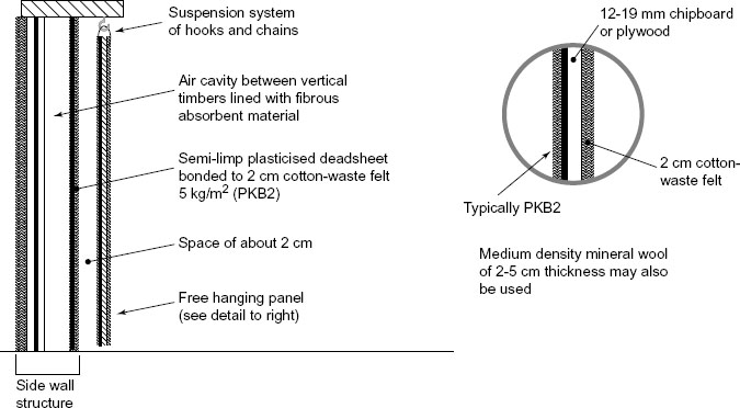
If additional isolation and absorption are required, it is possible to add a layer of material, such as Noisetec PKB2, over the felt on the rear of the wall. PKB2 is a kinetic barrier, and is a combination of a cotton-waste felt layer, of about 2 cm thickness, bonded by a heat process to a mineral-loaded deadsheet, the composite weighing about 5 kg/m2. If this is nailed over the felt, with the deadsheet to the first felt layer, it forms a deadsheet barrier, sandwiched between two layers of felt. Indeed, in the neutral rooms of the type being discussed here, PKB2, or a similar combination, would most likely form the first of the layers on the internal side of the stud walls. With a deadsheet/felt front, covering a 10 cm-deep cavity, partially filled with fibrous material, and backed by a double sandwich of plasterboard/deadsheet/plasterboard then felt/deadsheet/felt, followed by a further sealed air cavity before the structural or isolation wall, a very effective low frequency absorption system can be constructed, which will also be absorbent in the higher frequency ranges. This can be done without special tools or skills, and all in a space of about 22 cm. The construction is shown diagrammatically in Fig. 2.2(a).
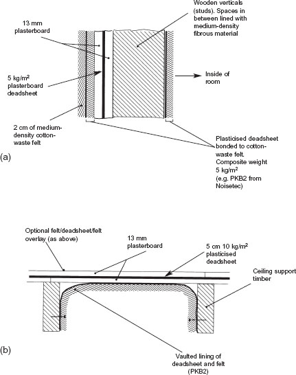
Figure 2.2 Acoustic control materials: (a) wall; (b) ceiling
The reason for the multiple layers of different materials is because different materials and techniques absorb by different means, and are effective in different locations and at different frequencies. Large panel absorbers, made out of plywood, for example, can produce high degrees of absorption, but they will tend to do so at specific frequencies, as they are highly tuned devices. Absorbers are considered to have a Q, or quality factor, dependent upon the degree of tuning. A high Q (highly tuned) absorber, may well absorb strongly at 70 Hz, but may absorb only minimally at 60 and 80 Hz. Obviously, to absorb a wide range of frequencies by such techniques, we would need to have many absorbers, but we may have problems finding sufficient space in the room to site them all.
If we lower the Q of the absorber, by adding damping materials, we will reduce the absorption at the central frequency, but we will widen the frequency range over which the absorber operates. We can therefore achieve a much better distribution of absorption by filling a room with well damped absorbers than by filling it with individual, high Q absorbers, in which case the absorption in any given narrow band of frequencies would be localised in different parts of the room. Another advantage of lower Q absorbers is that the resonances within them decay much more rapidly than in high Q absorbers. Resonators of a highly tuned nature, whilst absorbing much energy rapidly, will tend to ring on after the excitation signal has stopped, and hence may re-radiate sound after an impulsive excitation. Further details of the absorption mechanisms will be dealt with in later chapters, so let us now return to our neutral room.
The ceiling can be dealt with in precisely the same manner as the walls, but, given the 9–10 m minimum space across this room, joists of either steel or plywood sandwiches would seem appropriate. A typical plywood beam cross-section is shown in Fig. 2.3. The only significant difference between the wall and the ceiling structures would be on the inside, as shown in Figure 2.2(b), where the PKB2, or similar material, would be placed in arches, between the joists.
2.3.1 Design considerations
A studio room is an instrument in itself, so what we have by now managed to do is to destroy an instrument, but, if I am faced with a troublesome instrument such as a room of these dimensions might be (15 m 10 m 5 m) it is at times prudent to acoustically destroy it, and then re-build it predictably. With troublesome dimensions, the total suppression of the unwanted acoustic characteristics can be difficult to remedy by conventional means, and time and experimentation can be needed to assess the remedial work. For this reason the acoustical destruction of our problematical room is often a wise choice. So, to finally change the characteristic of this room in such a way that its acoustic dimensions no longer represent its physical dimensions in any simple manner, ceiling absorbers could be fitted as in Fig. 2.4, along with a panel absorber along one wall, as in shown Fig. 2.5. By this stage we do not have a neutral room in the recording sense, but, rather, except for the reflective floor, we have something very much approaching an anechoic chamber with a small amount of well-damped low frequency modal energy. Such a room could perhaps be excellent for measurement purposes, or could perhaps form the basis of one of the currently favoured concepts of control room designs, but as a room for recording music it would surely be found to be wanting.

Figure 2.3 Plywood beam construction – a 30 cm 15 cm beam of immense strength (all component parts glued and nailed to adjacent parts)
In the case of the studio room which we are discussing here, we need to create an acoustic which enhances the sound of the instruments without unduly announcing its own presence. We need a room which, as far as possible, favours all notes reasonably equally, neither ‘wolf’ notes, which stand out due to their coincidence with room resonances; nor causing other notes to have to be ‘forced’ to fight their suppression. The room should have a sonic ambience in which as wide a range of musicians as possible feel comfortable, both in themselves and with their instruments. Such a room allows a wide range of choice for the recording engineers in the positioning of microphones. It also allows a great deal of freedom in the positioning of the different musicians, either for the purposes of improved eye-to-eye contact (which can be very important to them) or for purposes of acoustic separation. However, the wall and ceiling absorbers which we have proposed thus far to overcome the room problems would be rather too absorbent for our requirements of ‘neutrality’. So, after controlling the room, we will have to selectively brighten it up, by means that we shall explain shortly. Before doing so, however, perhaps we can briefly digress, in order to look more closely at what we shall be seeking to achieve, and why.

Figure 2.4 Typical ceiling absorption system
2.3.2 Relative merits of neutrality and idiosyncrasy
Neutral rooms are flexible rooms in which work is usually quick and comfortable. An ensemble placed in a neutral room will tend to be heard and recorded with the natural predominances of that ensemble, with the room favouring neither any instrument nor position to any significant degree. However, if this were the be all and end all of recording, this would be a very short book. No, neutral rooms are not the best rooms for all purposes, a point which was perhaps first discovered, at least partially, by accident. There are many studios around which have rooms that were no doubt intended to be neutral, but which have failed to realise that goal. From time to time, a resonance in such a room, or a certain characteristic pattern of reflexions, can produce an enhancement of certain types of music and instruments played in them. They can become great favourites for the performances of those pieces. The same is true for the stages of certain concert halls, and indeed of other halls which have not necessarily been specifically designed for music. Unfortunately, in many of these, a characteristic of the room which enhances the music may only do so in certain keys or at certain tempos, so their suitability for recording becomes more limited.
For example, a symphony played in E major may well be strongly reinforced by a room resonance when certain parts are played with gusto. Perhaps if the coincidence is very fortunate, the main characteristic reflexion patterns will have a natural timing which produce a powerful effect if they coincide closely with a simple fraction of the beats per minute of the tempo. Such a room may give inspiration to the musicians, not only sonically lifting the music, but also encouraging a more enthusiastic performance. These rooms can have their places in both the recording and performing worlds in a way which a neutral room may never achieve, but though these rooms may achieve great results in a case such as that stated above, an orchestra performing a symphony in a different key, and with a different tempo, may have difficulties with the above room. If played in the key of F major for example, the resonances around the E may be entirely inappropriate, causing emphasis to notes which should not be emphasised, and masking and weakening the notes which the conductor would prefer to be dominant. In such rooms, for every peak in the response, there will be a dip elsewhere. Furthermore, series of ill-timed reflexions (echoes) may create confusion, and a degree of difficulty with the natural flow of the music. Not all musicians may fully realise what is going on, but many may comment on how they just cannot produce their best in that room with a given piece of music.
This is one of the reasons why much classical music is still recorded outside of studios, either in concert halls (with or without an audience) or in town halls, churches, or similar locations. It gives a choice of ambience for the producer, engineer and conductor to try to achieve the ‘ultimate’ from selected performances in selected locations. On the other hand, except for some very highly specialised recording companies, moving to a different location for each piece of music to be recorded for an album of pieces of music of less than symphonic length would be financially ruinous. What is more, choosing an idiosyncratic studio for the main piece would perhaps seriously compromise the remainder of the album. Such is one very important reason why neutral rooms are so widely used in the parts of the recording industry where high quality recordings must be able to be made on a predictable, rapid and reliable basis. They are especially useful for broadcast studios, where good quality recordings must be made quickly, and at reasonable cost as they are perhaps intended for a once-only transmission.
The next step in the design of our neutral room is therefore how to add into our relatively dead shell as many desirable features as possible, with as few problems as possible. The major pitfalls to be avoided are erratic changes in the reverberation time/frequency characteristic, bunched echoes in terms of their temporal spacing, and strong highly directional echoes (reflexions).
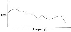
(a) An undesirable irregular decay response. This type of curve will cause colouration of the recordings
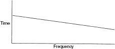
(b) A smooth, desirable decay response showing freedom from resonant colouration

(c) The lower plot would be typical of small rooms with less LF energy
Figure 2.6 Decay responses (reverberation)
Figure 2.6(a) shows the typical sort of reverberation response that we are trying to avoid, and Fig. 2.6(b) the response which is more in the order of what we are trying to achieve. The response of (a) shows lumps in the curve which are characteristic of unwanted resonances. The peaks are the frequencies which will continue long after an instrument has stopped playing, and the dips represent notes which may appear weak. The irregularities will therefore favour certain notes, suppress others, and mask many low level details of the sound. Such responses at low frequencies are often the result of large, parallel reflective surfaces which can support the strong, axial resonances. It was stated earlier that the angling of the walls away from parallel would help to redistribute the energy in the axial modes, but at low frequencies, the behaviour of sound waves is not always obvious.
In order to reflect at low frequencies, surfaces need to be of a size comparable to a substantial proportion of a wavelength, or the acoustic wave will tend to engulf them and pass around. In our neutral room, we can therefore avoid these problems by placing any necessarily large, reflective surfaces, such as large glass doors or windows, in positions where they do not directly face each other. Other reflective surfaces, necessary for the addition of life to the middle and high frequencies, can be arranged such that they have gaps in between them, the gaps being at intervals of less than half a wavelength of the highest of any troublesome resonances. Alternatively, they can be arranged in suitably random spacings.
2.4.1 What is parallel?
The term ‘parallel’ in its acoustic sense is very frequency dependent. Figure 2.7 shows two reflective walls, each 10 m long and spaced 10 m apart. They are geometrically parallel, and hence also acoustically parallel at all frequencies. A clap of hands at point X will generate a sound containing very many frequencies, and the sound will propagate in all directions from the source. The waves impinging on points Y and Z will be reflected back through the position of the source, and will continue to ‘bounce’ backwards and forwards, along the line Y–X–Z. Frequencies whose wavelengths coincide with whole fractions of the distance between Y and Z will go through positive and negative pressure peaks at positions in the room which coincide on each reflexion. They will drive the resonant modes, which strongly reinforce each other, and will tend to be audible in some points in the room but not in others. A 70 Hz standing wave pattern is shown in Fig. 2.8. The light areas show regions of low pressure changes, where the waves would be inaudible, and the dark areas show the regions of high pressure changes, where the 70 Hz content of the sound could be clearly heard.
If we now angle the walls, in a manner shown in Fig. 2.9, with one end of one wall swung in towards the other wall by 1.5 m, we will have two walls with a 15% inclination. Now, a handclap at point X will again send a wave in the direction of Y, which will return to the source point as a reflexion, and will continue on to point Z. A direct wave will also propagate to point Z, and both the direct and reflected waves will reflect from point Z, not back towards point Y, as in the case of the geometrically parallel walls, but towards point F. They will then reflect to point G, and on to point H. Unlike in the case of the geometrically parallel walls in Fig. 2.7, a person standing at point X will not hear the chattering echoes, and most of the resonant energy of the room modes will be deflected into the tangential type, taking a much more complicated course around the room. However, whilst the higher frequencies will be deflected along the pathways Y–Z, Z–F, F–G, G–H, at lower frequencies, where the wavelengths are long, axial modes may still persist. This suggests that at low frequencies, the walls must still be parallel in an acoustical sense.
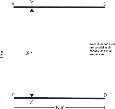
Figure 2.7 Geometrically parallel walls. A sound emanating from point X will spread in all directions, but the sound waves travelling in the directions of points Y and Z will reflect back along the line of their original travel. They will continue to reflect backwards and forwards along the same path, creating echoes, until their energy is finally dissipated by losses in the walls and the air. Such are the paths of axial modes, which, when wavelengths coincide with whole fractions of the distance between the walls, produce modal resonances – see Fig. 2.9
Figure 2.10 shows the 70 Hz standing wave pattern for a room with one wall angled to the same degree as that shown in Fig. 2.9. The pattern is remarkably similar to the one shown in Fig. 2.8. Although Fig. 2.9 shows that the angling of the walls has produced a very different path for the hand-clap echoes, and will be quite dispersive at high frequencies, at low frequencies very little has changed. Essentially, for geometric angling to be acoustically effective, the pathlength differences for subsequent reflexions must be a significant part of the wavelength. With the wavelength of 50 Hz being about 8 m, the degree of angling required to be acoustically non-parallel would perhaps be possible in buildings the size of concert halls, but would be likely to consume too much potentially usable space in a conventional recording studio.
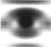
Figure 2.8 Magnitude of pressure field due to a point source between the two walls depicted in Fig. 2.7
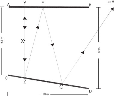
Figure 2.9 Here, the general situation is that of Fig. 2.7, except that one of the reflective surfaces has been moved to create a geometrically non-parallel arrangement between the surfaces A–B and C–D. Distinct echoes, as produced by the surfaces in Fig. 2.7, are not possible, as the reflexions will not follow repeating paths. Mid- and high-frequency sounds emanating in the Y and Z directions, from position X, will subsequently follow the path Z, F, G, H etc. At low frequencies, however, all may not be too different from the conditions of Fig. 2.7 – see Fig. 2.10

Figure 2.10 Magnitude of pressure field due to a point source between the walls depicted in Fig. 2.9
The effect of a limited degree of wall angling on the response of a room is shown in Fig. 2.11. The two traces show the performance of the walls shown in Figs 2.7 and 2.9. Above 300 Hz, the non-parallel walls show a clear reduction in modal energy when compared with the parallel walls, but below about 100 Hz there is little difference between the two traces, showing that, in the acoustic sense at least, the walls in Fig. 2.9 are still parallel. The reduction in modal energy above 300 Hz is largely due to the fact that the wall angling drives more of the higher frequency modes from the axial to the tangential type. The tangential modes not only have more complicated paths to travel, but also strike the walls at oblique angles, which tends to rob them of more power than is lost in the more perpendicular impacts of the axial modes. It can thus be seen that whilst the angling of walls can have a very worthwhile effect at frequencies above those which possess a wavelength which will be subsequently shifted in position by a half wavelength or more on their return to the source wall, at frequencies below these, the effect will simply be that of a comb filter, as shown in Fig. 2.12. Here, as the frequencies are swept downwards from the above half wavelength frequency, the sweep passes through alternately constructive, neutral and destructive regions. Strong comb filtering at low frequencies is usually musically disruptive and very undesirable in recording studios and music rooms in general, though it exists to some degree in all reflective spaces. At higher frequencies, our ears use it for many beneficial purposes, such as localisation and timbral enrichment.
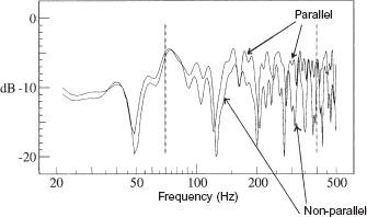
Figure 2.11 The above plots show the response at point X in Figures 2.7 and 2.9. It can be that, at frequencies below around 80 Hz, the effect of the angling of one of the reflective surfaces has had only minimal effect. Above about 200 Hz however, the effect is quite pronounced.
So, whilst the angling of reflective surfaces is a viable technique for mode control at middle and higher frequencies, at low frequencies, geometric solutions are usually not able to produce the desired results, and hence absorption must be resorted to, though diffusive techniques are beginning to become a practical reality. These will be discussed later in the chapter. Parallel surfaces also produce the repetitive chatter or ‘slap back’ from impact noises, somewhat akin to the ever-receding images seen when standing between parallel mirrors, and this reflective chatter can be equally as undesirable as the resonant modes in the destructive effect on the music. In the following sections, we shall begin by looking at practical solutions to the circumvention of these problems, whilst producing a desirably neutral acoustic.

Figure 2.12 The averaged power spectrum of a signal with one discrete reflexion. Comb filtering is revealed clearly on a linear (as opposed to a log) frequency scale, where the regular nature of the reflexion-produced disturbances can clearly be seen. In the instance shown above, the additional pathlength of the reflected signal over the direct signal was just under 10 m, producing comb filtering with dips at a constant frequency spacing of just under 40 Hz.
2.4.2 Reflexions, reverberation and diffusion
We are now faced with the problem of how to put the ideas so far discussed into a practical form. Unfortunately, there are so many ways of doing this that a whole book could be filled on this topic alone, so we will have to take an approach which will incorporate a number of solutions in one design. From this, hopefully, it will be possible to gain something of a feel of the range of possibilities open to designers, and the way that these can be put into general recording practice. What is necessary for musical neutrality in rooms of the size under consideration here (650 m3) is a reverberation time (or, in these cases, more correctly a decay time) in the order of 0.3 to 0.5 seconds, perhaps rising to 0.7 or 0.8 seconds at low frequencies, with the rise beginning gradually below 250 Hz. Figure 2.13 shows a typically desirable frequency/time decay response of such a room; the time indicated being that taken for a sound to decay to 60 dB below that of its initial level.
There are two general techniques involved in creating reverberation in such a room; either by reflexions or by diffusion. In recent years, companies such as RPG1 in the USA have created a range of acoustic diffusers capable of operating over a wide range of frequencies. These are constructed on principles based on sequences of cavities whose depths alternate according to strict mathematical sequences. They can be made from any rigid material, but perhaps wood, concrete and plastics are the ones most frequently encountered. The mathematics were proposed by Professor Manfred Schroeder2,3,4,5 in the 1970s, and are based on quadratic residue sequences. The effect of the cavities is to cause energy to be reflected in a highly random manner, with no distinct reflexions being noticeable. The random energy scatter creates a reverberation of exceptional smoothness. By using such diffusive means, the overall reverberation time can be adjusted by the ratio of diffusive surfaces to absorbent surfaces, though for an even distribution of reverberation in the room, a relatively even distribution of diffusive surfaces is required. Except for the floor and windows, all other surfaces are usually available for diffusion.

Figure 2.13 RT60 of a good neutral room. Low frequency reverberation times can be allowed to vary with room size
With the availability of diffusers, achieving the desirable degree of ambient neutrality may well at first seem to be a simple matter of adding diffusers until the desired reverberation time is achieved, but from such a room there would usually be a lack of musicality. What such a room would lack are discrete reflexions. Fortunately, they are easily introduced, as they are of great importance to both the musicians, and their audiences. On concert stages, they are needed by the musicians to reinforce the sound of any instrument or ensemble. As mentioned earlier, reflexions divide into two groups, late reflexions and early reflexions. The early reflexions, arriving less than 30 or 40 ms after the direct sound, are heard by the ear as a timbral enrichment of the instruments. The later reflexions, arriving 40 ms or more after the direct sound, add spaciousness to the sound, which for many types of music is essential for its enjoyment. The dimensions of our example of a large neutral room were chosen such that an instrument in the centre of the room would produce only late reflexions from the wall surfaces, but of course, from the floor and ceiling, the reflexions would necessarily be of the early type. Instrument to floor distances are normally relatively constant; floor reflexions typically being in the 5 to 10 ms region. Any ceiling reflexions in this room would be in a borderline 20 to 40 ms region, dependent not only upon ceiling geometry, but also upon whether diffusive, reflective or absorbent surfaces predominated. In later chapters dealing with more reverberant spaces, we shall look at reflexions further, but in the neutral type of room under discussion here, whatever reflexions exist should tend to be reasonably well scattered, otherwise they will develop a character of their own, and the room would lose its neutrality.
2.4.3 Floor and ceiling considerations
Let us now look at possible ceiling structures for our neutral room. As we discussed earlier, the nature of the floor has been chosen to be wood. Carpet tends to produce a lifeless acoustic, uninspiring for the musicians, and unhelpful for the recordings. Stone was rejected, partly for its ‘harder’, more strident reflective tendency, but also on the practical ground of slippage. Floors of neutral rooms overwhelmingly tend to be of wood. At this point of the design stage (see Fig. 2.2(b)) we have a very dead ceiling at a height of about 4 m 50 cm. We cannot come down too much below this, as the reflexions which we would introduce would tend to become of the tone-colouring, early nature. What is more, too low a ceiling would preclude the siting of microphones above any instruments at a height which may be necessary to cover any given section of musicians.
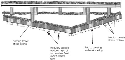
One solution to such a problem is to construct a ceiling of wooden strips, with spaces in between them, which will allow a good proportion of the lower frequencies to pass into the absorbers behind. They therefore provide mid and high frequency reflexions, but without allowing an unwanted low frequency build-up. As mentioned earlier, in order to reflect at low frequencies, surfaces need to be of sizes comparable to the wavelengths to be reflected. We can therefore have some degree of control over the lower limit of our desired reflectivity by providing gaps in our reflective surfaces at appropriately chosen intervals. Once again, with this complex subject, there are so many ways of achieving each objective, but here I shall describe some of the possibilities within one technique of specific interest. The strips to be described could be of hardwood or softwood, and could be plain, varnished, painted, rough or smooth. Each will give its own subtle character to the sound. Hardwoods, untreated, can produce quite interesting sounds, but in today’s ecological climate, I personally refuse to specify any woods of an exotic or not too easily replenishable nature. Sound is of course important, but we do have a planet to protect as well.

(a) Alternate hard and soft surfaces
(b) Irregular hard/soft surfaces

(c) Absorbent spaces and curved, diffusive surfaces
Figure 2.14 Various ceiling constructions for a neutral room
Obviously, we do not want to encourage the build-up of resonant energy in any modes which would unpleasantly colour the sound, so the ceiling surface can be broken into a series of angled sections, set to produce what the designer would consider to be the most appropriate angle of reflexions. A selection of possibilities for ceiling designs is shown in Fig. 2.14. Figure 2.15 shows a pattern of wood/space ratios which is based on a numerical sequence, not dissimilar to the one used for the diffuser cavities referred to earlier, and indeed there is a certain amount of diffusion from this type of arrangement, which is partly the result of diffraction from the edges of the wooden strips. The purpose of this arrangement, however, is to help to prevent any noticeable patterns forming in the reflected sound-field.
The BBC6 (British Broadcasting Corporation) have developed a very successful range of ceiling tiles which fit into the typical sort of false-ceiling structures used in many offices and broadcast studios. In fact, using a steel-framed grid for a false ceiling allows great flexibility in the introduction of absorbent, reflective or diffusive tiles, which can be an excellent way of providing a room with a degree of acoustic variability. In the broadcasting world, these systems are widely used, but for my own tastes, in commercial music recording studios, their appearance is too industrial to provide what I consider to be the necessary decorative ambience for musicians to feel comfortable and creative. However, I realise that these things are highly personal, and for people who find these prefabricated tiles pleasing to look at, they can be safe in the knowledge of their excellent acoustical performance.
2.4.4 Wall treatments
Figure 2.16 shows a possible wall layout for our neutral room, and it can be seen from the figure that parallel wall surfaces have been avoided. Where the frequencies begin to render the walls acoustically parallel, they are allowed to pass into absorbers, either directly or after first reflexion. Care has been taken to make sure that glass windows or doors do not face directly towards any parallel reflective surfaces. In the room shown, the control-room door/window system is set into a relatively absorbent wall, so one of the walls is now defined.
That now leaves us with three wall surfaces to complete. For musical neutrality, we do not want too much reflective or reverberant energy, but just enough to give the room sufficient life to stop the instruments from sounding too dead. It is similar to a little seasoning, bringing out the flavour of the food without overpowering it. The glass surfaces, the entire floor, and the ceiling reflexions are more or less enough for this. We also have the problem that if we make the walls reflective to any significant degree, we may create unduly reflective areas for any musicians playing close to the walls. In fact, in the corners of the room the colouration could become most unnatural if bounded by the floor and two reasonably reflective walls, all providing early reflexions in addition to those from a borderline early/late ceiling.
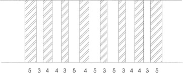
Figure 2.15 Typical arrangement of wood strips and absorbent openings. The widths of the strips and openings are based on a numerical sequence that provides more or less equal areas of absorbent and reflective surfaces, but without any simple regularity which could lead to problems at certain frequencies that may have properties coinciding with the regularity. The numbers in the diagram represent the relative dimensions of the adjacent strips and openings
For reasons of structural integrity if we have walls covered with fabric for decoration, we need wooden rails, at waist height or a little higher, to prevent people from ‘falling’ through the fabric. We need skirting boards so that the floors can be cleaned without soiling the fabric, and we may also need to put rails at shin height as a convenient mounting for microphone sockets and electrical outlets. Figure 2.17 shows a small version of a room with such fittings, but should such a room be considered to be just a little too dead, or in cases where only a rather small area of glass is to be used, then an arrangement such as that shown in Fig. 2.18 can be employed. The reflective surfaces are based largely on the concepts of Fig. 2.15, but the ratio of the areas of the spaces to the facing timber can be adjusted to produce the required degree of acoustic ‘life’. The fabric covering is for decorative purposes only, and so should be of a type which is acoustically transparent. Many fabrics can be surprisingly reflective, and if stretched too tight for neatness, they may well also act like drum skins. Lightweight ‘stretch’ fabrics are useful here.
So now we have something approximating to a musically neutral room, which tends neither to add character to the sound of an instrument nor ‘suck out’ all of its life. Rooms such as the ones being described here are excellent for recording efficiently, rapidly and predictably, but if they are the only spaces available for recording, then the practice still harks back to the philosophies of yesteryear, and their more ‘technical’ correctness. Perhaps these rooms had more of a place when control rooms were less precise, when monitoring conditions were less predictable, and when the electronics of the recording chain itself were more coloured in their sound character. Perhaps it is now a good time to develop these thoughts further, and look at the alternatives. Remember, though, neutral rooms are very necessary in the broadcast industries, and in recording facilities where rapid results are necessary from a wide range of music and instruments. For these purposes, they excel.

Figure 2.16 Possible layout of neutral room

Figure 2.17 A relatively small room with a very neutral acoustic characteristic. Studio room of the Ukrainian Air Force, Cultural, Educational and Recreational Centre, Vinnitsya, Ukraine

Figure 2.18 View from above, of a wall structure and treatment for a totally ‘neutral’ room

Figure 2.19 Possible layout of a neutral room with a little flexibility (doors and windows omitted for simplicity). The ceiling could be typically one of those shown in Fig. 2.14.
The walls:
A Low frequency absorber with controlled upper mid/higher frequency reflectors. Similar surface features to those shown in Fig. 2.17
B Wood-panelled, reflective wall
C Wide-band absorber, faced with fabric-covered frames
D Diffusive wall, with absorbers between diffusing half-cylinders
E Reflective, double-sloped wall, faced with wooden panelling
As further food for thought, Fig. 2.19 shows a neutral room with a somewhat more ambitious approach. It is neutral on the ‘macro’ scale, but on a more ‘micro’ scale, in close proximity to the different wall surfaces, a degree of variability of acoustic performance can be achieved. This room therefore straddles the borders of neutrality and variability, so perhaps that will lead us nicely into the next chapter.
1 D’Antonio, Peter, ‘Two Decades of Diffusor Design and Development’, AES Pre-print, 99th Convention, New York (1995)
2 Schroeder, M. R., ‘Diffusive Sound Reflection by Maximum Length Sequences’, Journal of the Acoustical Society of America, Vol 57, No 1 pp 149–150 (1963)
3 Schroeder, M. R., ‘Comparative Study of European Concert Halls: Correlation of Subjective Performance with Geometric and Acoustic Parameters’, Journal of the Acoustical Society of America, Vol 56, No 4 pp 1195–1201 (October 1974)
4 Schroeder, M. R., ‘Progress in Architectural Acoustics and Artificial Reverberation in Concert Hall Acoustics and Number Theory’, Journal of the Audio Engineering Society, Vol 32, pp 194–203 (1984)
5 Schroeder, M. R. and Gerlack, R., Response to ‘Comments on Diffuse Sound Reflection by Maximum Length Sequences’, Journal of the Acoustical Society of America, Vol 60, No 4 p 954 (October 1976)
6 Walker, R., ‘The Design and Application of Modular, Acoustic Diffusing Elements’, Proc of Institute of Acoustics, Vol 12, Part 8 pp 209–218 (1990)