
Room combinations and operational considerations
As has no doubt become clear by now, no one room can perform all the functions which may be required for the recording of the whole range of probable musical performances. The large, variable room is perhaps the best option, if money and space allow such a room to be built, but even the best such room can never mimic the performance of a good, small live room, or a good stone room: at least not without absurd complexity of structure and mechanisms. We should now therefore consider how we could put together the pieces so far discussed in order to make a viable, practicable, and efficiently flexible studio package.
Let us imagine that we were presented with a building in which to construct a studio, and that we had the luxury of 500 m2 of floor space and 6 m of ceiling height. One option would be to sub-divide it as shown in Fig. 8.1, which would give us enough space to construct a large, variable, general recording area, plus a stone room, a moderately live room, and a vocal/dead room. However, the layout of such rooms is full of compromise, forced upon us by many conflicting priorities. Ideally, everybody needs to be able to see the control room, but also, everybody needs to be able to see each other. At the same time, the general influence of the positioning of the smaller rooms should not detract from the optimum shape of the main studio area. This may all seem rather obvious, yet it is surprising just how many studios are built without even the most basic of these requirements being given their due consideration – this even includes some studios which have ostensibly been professionally designed.
Figure 8.2 shows an actual situation that I was faced with, in a 90% completed form, when I was asked to act as consultant for the finishing of the job. Believe it or not, over $50,000 had already been spent on the rooms. The designs had been done by a theoretical acoustician with some theatrical acoustics experience, and not by a specialised studio designer, and all the rooms had been designed around the use of large semi-cylindrical diffusers, Helmholtz resonators, and absorbent/diffusive tiles made from gypsum and mineral wool. All the rooms had been designed to classic RT60 figures, and somewhat surprisingly, all had been aimed at a somewhat similar acoustic performance, except for the slightly longer RT in the larger room. The windows and doors had been situated in accordance with structural simplicity, rather than acoustical, operational, or musicians’ needs. Perhaps this fact, more than any other, made the task of modifying this studio all but impossible.
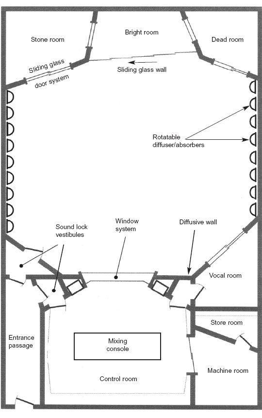
Figure 8.1 Layout of hypothetical 500 m studio, but based on an actual design
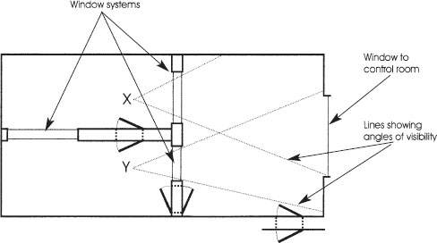
Figure 8.2 Studio designed by cinema acousticians. Musicians in positions X and Y, the natural positions for good visibility into the larger recording room and the control room, are unable to see each other
I was too soft hearted to suggest to the owners that they should demolish everything and begin again, so I tried to rescue what I could of the original structure. After some days of sketching and discussion, it was ultimately the owners themselves who suggested a total re-build. What was so distressing was that the simple re-positioning of the internal walls, doors and windows, such as shown in Fig. 8.3, it would have rendered the room much more rescuable. What is more, it would have cost no more to do so than to build what had actually been built. It seems however that the only design considerations had been separation and acoustic control. Neither of these things should be achieved at the sacrifice of the ease and comfort of the musicians, yet in this instance it turned out that the designer had failed, almost totally, to consider the needs of the musicians.
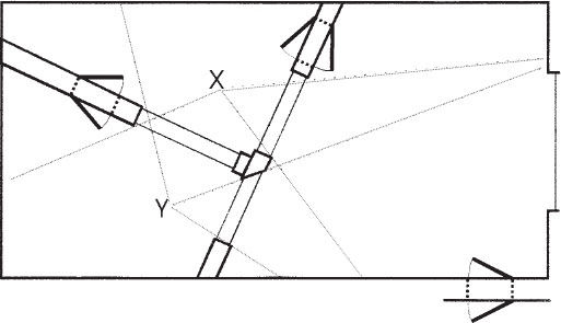
Figure 8.3 Layout which could have been workable using similar space and materials as those in Fig. 8.2
The sad thing about the above situation is that with a little more forethought and experience, the use of the layout of Fig. 8.3 would have allowed the construction of an excellent live room in section X and good vocal room in section Y, and the shape of the larger room would have allowed much better acoustic control, without having to resort to the ‘battleship’ methods which lost so much usable space in the original layout. Anyhow, now that the surprising ease with which some well educated people can get things wrong has been established, we can move on to take a look at things in a more orderly manner.
8.1.1 Demands from control rooms
Even ‘external’ things, such as the control rooms will make their demands on the design of the studio rooms. As I explained at great length in my book Studio Monitoring Design, whether you have a wonderful set of studio acoustics or not, it is like driving blind if the control-room monitoring and acoustics are not sufficiently sonically neutral and free from idiosyncrasies of their own. To make the best of what the studio acoustics, microphones, and musicians have to offer, it is imperative that the control room should not be compromised. The most likely compromise in this area is to visibility, which is indeed very important, but there are optimal locations in control rooms for loudspeaker positions, and I, personally, do not agree with the pushing of the monitor loudspeakers into high locations, where the ear perceives things very differently than from a horizontal direction, all for the ‘luxury’ of an enormous front window.
Large windows are problems in themselves. The bigger they get, the more they tend to allow sound through, or to resonate in unwanted frequency bands, unless they are of a very great weight, in which case they may need to be custom-made by a specialist glass factory, the cost of which can be alarming. Two-way closed-circuit television is one possible solution for visibility between the control room and any out of the way places, but there is normally the problem of the 10 or 15 kHz timebase whistles from the TV monitors. Some people find these to be extremely irritating, but perhaps more dangerously from a recording point of view, many people cannot hear them at all. In such cases, if they do pick up on the recording microphones, and especially if any top boost is applied on the console, then they can pass unnoticed onto the master recording, only to subsequently irritate the purchasers of the final product.
We also need to consider access to and from the control room, which in my designs usually means access via a side wall or the extreme sides or centre of the front wall. For me, the rear wall of a control room is sacrosanct, and should only be used for absorber systems. It is perhaps the most critical surface, as it takes the full impact of the incident wave from the monitor system, and anything coming back from that wall will colour the perception in the room. The low frequency absorber surfaces need to be as large as possible, so penetrating them with doors is generally undesirable. I now try to avoid the use of sliding glass doors in the centre of the front wall, even though I was one of the pioneers of the concept, at The Manor studio in Oxford, England in 1975. Unless the glass is very heavy, so much so that perhaps opening and closing the doors becomes a difficult exercise, any LF resonance which exists in the door system will not only cause a perceivable resonant overhang, but will also absorb some of the impact from the bass end of the monitor system.
If the control room is sufficiently wide, then a heavy window can be placed centrally, between the monitors, and heavy doors of composite nature can be located on the outer sides of the monitors. These can provide access to the studio rooms, and to the reception areas or access corridors if necessary. If I must provide side doors into a control room, I prefer them to be as far to the back of the room as possible, to avoid disturbing the absorption system on either side of the mixing position. However, if they must be at the sides, they can be angled so as to reflect any sound which strikes them into the rear absorber. Every situation is different, though, with its own set of specific demands, but that, of course, is what helps to make studio design so interesting.
In Fig. 8.1 the control room is flanked on one side by an access corridor, and on the other side, by a machine room and a vocal room. If any one of the studio rooms needs to be alongside the control room, it is better that it is the most acoustically dead of the rooms, as the SPL which develops in the live rooms can present much greater sound isolation problems if the live rooms are adjacent to the control room. Also, usually, the dead rooms will be used for much of the vocal overdubbing work. This process can consume a great deal of time, so a location close to the control room is convenient and expeditious. The arrangement shown allows access and visibility directly to and from the control room and the studio, so whether doing live vocals or overdubs, the vocalist will not feel too isolated.
So, already, having discussed so little about the studio layout itself, we have been diverted by considerations from some seemingly secondary sources, but their pull is great, and any studio designed without due consideration of the widest spheres of influence will likely fail to achieve its full potential. Different designers will have their own very special priorities which they will try to avoid compromising, and each of these points is likely to be based not only on knowledge of facts but also on insight gained through years of practical experience. This is largely what separates studio designers from other acousticians. In each case, the experiences will have been different, and the individual tastes of the designer will be different, so this will lead to some very different designs. This is actually quite fortunate, as without variety, things would be a little dull. Obviously it must be borne in mind that I, too, am a product of my circumstances, so a degree of personal leanings will be influencing what I write, and what I design. There is no bible which governs this subject absolutely.
Figure 8.1 shows a very attractive layout, but such a flexible option would be expensive to build. Studios are usually built on budgets that must be earned back over a matter of a few years, and so must be constructed with the appropriate economic considerations. When we cut our budgets, we usually also cut our options, so a designer must consider carefully the most likely uses to which the studio will most frequently be put. If it is proposed to record many voices, or chamber orchestras, then obviously a stone room and a live room would not be an appropriate choice of combination. In fact, such a combination would be unlikely to be a good choice in any circumstances that spring to mind. I do know of a few studios who earn their livings from a single stone room or live room, but they cater for a niche market. I am sure that if any of them were to build a second studio room, then it would either be a dead room, as described in Chapter 7, or a room with some degree of variability.
An interesting problem faced me recently. I was designing a studio for a company which had already built up a good base of clientele, but in order to continue in operation they had to rebuild, to improve the sound isolation and general acoustics. The studio had grown from a single studio to two studios, but the building was only converted into its original studio form with the one studio in mind. Studio businesses do not always develop as expected, and in this case they needed to be able to record a wide range of small musical groups, including acoustic, rock and electronic. They also did much voice-over work for foreign language replacement of television programmes and cartoons. The two new studios were required to operate either separately, or with the second control room relegated to being an editing room, and its studio room put into use with the main control room. The final layout is depicted in Fig. 8.4.
In this design, Control room 1 was the main control room for music recording. Previous experience had led the owner to believe that they needed a good live room, and a vocal room which would not colour the sound. Control room 2 would not be used for serious mixing purposes, but should be neutral enough to make a good editing room, and to be able to function as a control room for overdubs or dialogue replacement. In Fig. 8.4, it can be seen that Control room 2 has an adjoining studio (Studio 2), which is only large enough for one musician at a time, or perhaps a trio of backing vocalists, but this room also has to serve as a third recording space for Control room 1. The problem was that Studio 2 would best serve Control room 2 if it were a room which was as dead as the ones described in Chapter 7, but Control room 1 already had such a room adjacent to it, so doubling up on such rooms would seem to serve little purpose. It was eventually decided to make Studio 2 a bi-directional room, which could serve as a relatively dead room when being used with Control room 2, but would have more life when used with Studio 1.
It was presumed that when being used as an extension to Studio 1, the musicians would be facing Control room 1, and when working with Control room 2, they could face the opposite direction without losing visual contact with Control room 2. Figure 8.5 shows the idea in more detail. The main problem with this option was how to make a small room with the required brightness, but without the boxiness which usually accompanies such designs.
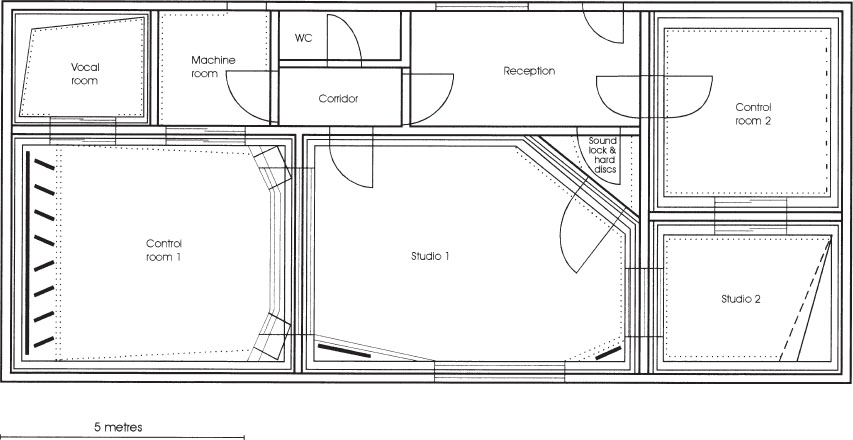
Figure 8.4 General layout of a small studio complex (Tcha Tcha Tcha Studios, Lisbon, Portugal)
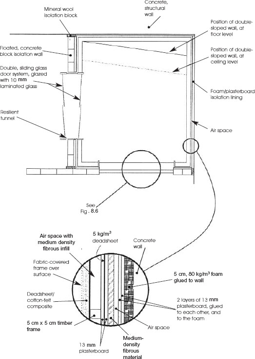
Figure 8.5 Plan of small room using the double-sloped Geddes wall principle
8.3 Isolation considerations: doors and windows
Isolation was a great priority, not only because the two studios had to be able to work separately, but also because the poor reputation due to the bad separation between the old studios had to be ended once and for all. The wall between Studios 1 and 2 was a massive, sand-filled concrete block affair, floated away from the structural walls, floor and ceiling with high-density mineral wool. Each side of the wall was treated with 8 cm of 80 kg/m3 polyurethane foam then by two sheets of plasterboard, all layers bonded with contact adhesive. All three studio rooms and both control rooms were separately floated on 120 kg/m3 polyurethane foam (Arkobel) but Studio 2 had a second floated floor, of different density and thickness to the other floated floors. This was to avoid any common resonances in similar construction methods which could have reduced the isolation at any common resonant frequencies. The shell treatment of Studio 2 was essentially the same as that described in Chapter 7. The room began as a dead room, with the additional life of the double glass-door system to the control room, plus a quadruple-glazed window to Studio 1. In fact, before looking in detail at the system of livening Studio 2, perhaps we should first look here at the door and window systems.
8.3.1 Sliding doors
The two door systems were each made out of two panels, one fixed and one opening (sliding). The doors were mounted in the frames of each of the adjacent, floated boxes, whose walls were separated by a sand-filled concrete block wall. The non-parallel mounting of the doors helps to reduce the resonant energy in any modes in the cavity between them, and also allows them to avoid forming parallel surfaces with the opposing walls inside of their respective rooms. The glass chosen in this instance was 10 mm laminated glass, which is quite heavy, and also, by virtue of the laminating, very acoustically dead. The laminating layer acts as a constrained layer, in the same way that the deadsheet layer operates when sandwiched between the two sheets of plasterboard in the wall structures. The laminated glass also adds an extra element of safety as it is very strong, easily resisting the impact of wooden blocks thrown at it quite forcibly. There is little risk of people breaking it by accidentally walking into it, or knocking a guitar against it.
Between the two doors a tunnel was constructed, but was connected to one door frame rigidly, and to the other only by means of silicone rubber. The tunnel is therefore an extension of one room, but connects it resiliently with the other room. By this means, no significant direct transmission of sound can take place between the two rooms. The tunnel passes through the concrete wall, but it is spaced off with mineral wool or polyurethane foam to avoid direct contact with the isolation wall, and hence to prevent the transmission of sound into the main structure. Ideally, if conditions allow, the two doors should be of different widths, and the glass of different thickness, in order to reduce any transmission of sound via any common resonances, but one has to be careful here in applying rules too generally. Perhaps a 6 mm and 10 mm pair of glass doors would provide a better isolation than two 8 mm glass doors, which would contain the same total thickness of glass (16 mm), however, weight is an important factor, and experience has taught me to use the heaviest and most acoustically dead glass that I can find readily available. A 12 mm and an 8 mm glass would probably be marginally better than two 10 mm glasses, but the difference is rarely worth the extra cost of different door frames, and glass prices tend to rise disproportionately with thickness: 25% extra thickness can sometimes mean 100% more price. Varying the area of the panels is often just as effective as varying their thicknesses, and is often a less expensive solution.
8.3.2 Window systems
The window system between Studios 1 and 2 raises a number of interesting topics regarding window design. In this case, quadruple-glazing was used, with two panes mounted as widely apart as possible on the foam/plasterboard linings of the concrete centre wall, and one further pane on each of the floated boxes. The sound isolation between these rooms was more important than usual, because there would be times when the two studios were working independently, perhaps with a rock band in Studio 1, and a voice-over in Studio 2.
As explained earlier, the 20 cm, sand-filled concrete block wall was covered on each side with 8 cm of 80 kg/m3 reconstituted foam and 2.5 cm of plasterboard, which gave a total wall thickness of just over 40 cm. The hole in this wall was sufficiently large to allow as much visibility as necessary, but no larger, as the bigger the hole in the wall, the less the resulting isolation. The lines of sight were carefully assessed, and the minimum practical hole size was used for the windows. The central panes were different, one a vacuum sealed, double unit, and the other a pane of 8 mm plate. The windows in the walls of the floated boxes were correspondingly larger to allow the angular visibility, as shown in Fig. 8.6.
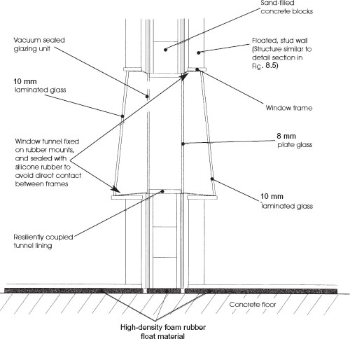
Figure 8.6 Quadruple-glazed window system
Again, as with the doors, tunnels run from the outer windows to the inner ones, fixed to the frames on the floating rooms, and attached by silicone rubber to the central windows. These are usually lined with carpet, to avoid chattering in the gap, and are normally made of a relatively acoustically dead material, of not too great a thickness, which will allow sound to be absorbed not only by the tunnel itself, but also by the soft materials packed around the tunnel. In this specific case, the outer panels of glass were of 10 mm and 12 mm laminated glass; different thicknesses being used because each was the same width and height. They were also angled such that they would reflect any sound striking them up into the absorbent ceilings of each of the rooms.
8.3.3 Multiple glazing considerations
In this instance, quadruple-glazing was used in order to reduce the sound transmission at each change in wall structure, and in particular to prevent the sound from reaching the concrete wall. Effectively, the inner pair of windows were on the plasterboard layers, which in turn were isolated from the concrete wall by polyurethane foam, but in many normal circumstances, say between two simple walls, a greater space between the windows can often be more effective than more windows. In other words, if the space between two walls is 80 cm, then it can be more effective to use two panes of glass of 10 mm and 12 mm, than to split the tunnel into spaces of 20 cm, 35 cm and 25 cm by the use of four panes of mixed 10 mm and 12 mm glass. It is possible that the mid and high frequency isolation of the quadruple-glazing would be better, but that the low frequency isolation would be worse, as the space between the panes is an important factor in low frequency isolation. There are few absolute, hard and fast rules to this, as the wall structures, the degree of possible angling of the glass panes, and the type of work in which the studio is usually engaged will all add their own special conditions. For example, a voice-over studio, or a talk studio, is unlikely to be placing great importance on very low frequency isolation, as low frequency sounds are not likely to exist at high level on either side of the window. In this case, the quadruple-glazing option may be preferred, but for a studio mainly producing dance music, with lots of low frequencies, then quite possibly the double-glazing larger space option would be preferable. Each case must be assessed individually.
8.3.4 High degrees of isolation
There is obviously no need to produce isolation in a window system that is any greater than the isolation provided by the walls which they penetrate. A 70 dB window system in a 55 dB wall system only succeeds in wasting money. However, if very high isolation window systems are required, they may become absurdly expensive. Eastlake Audio installed a window system1 in Belgium, where an isolation of 80 dB was required between the control room and the studio. The glass panes were 11 cm thick (yes, centimetres!), and weighed almost 1 ton each. The thickness was the maximum that the particular glass-making machines could stand the weight of, and the transport was very difficult. The original specification called for 14 cm glass, but when it was found that it could not be acquired in Europe, panes of 11 cm were used with a greater space between them than had originally been planned. The cost of all of this I dread to even contemplate. In fact, the total weight of the two rooms, floated on steel springs, is almost 2000 tons, with 9 tons of rubber in the walls. It is certainly impressive, but such would hardly be practical solutions in most cases. In fact the following quotation from David Hawkins, the owner of Eastlake Audio, just about sums up the reality: ‘Normally, when people ask for isolation figures of this type (80–85 dB), I generally suggest that they build the rooms in different streets.’
Conventional, hinged doors also pose their problems however, doors are usually able to be positioned in areas of the structure which are less critical than the normal window locations. What is more, right-angled bends and isolation vestibules can often be incorporated into the designs of door systems. In general, doors need to be heavy, acoustically lossy, and well sealed into their frames, but perhaps an extreme case can once again be outlined by describing the doors at the Belgian studio mentioned above. They used industrial doors with a nominal isolation value of 55 dB, which were employed either in pairs, or in triple sets between critical areas. Each door weighed 300 kg, and was suspended on ball-bearing hinges. When the closing handles are turned, they apply a pressure of 400 kg on the door seals, and hence on the walls. The repercussion of this is that the structure of the walls must be very strong and heavy, which implies more cost, and places restrictions on where they can be used. Not in a third-floor domestic bedroom studio, for example.
It is often difficult to get the fact across to people that 70 or 80 dB of isolation demands the same degree of treatment, irrespective of the purpose for which it is needed. ‘But I only want it for practising my drums’ is a cry so frequently heard. It is as though people expect that the cost of isolation somehow reflects the cost of what they are doing. Because they are only spending the cost of a drum kit, they expect that the isolation to the bedroom of a neighbour will somehow be cheaper than if they were spending a hundred times as much on a complete set of studio equipment. Obviously (or at least it should be obvious) the two situations will have an identical isolation requirement, whether the drums are used for practice only, or for a very serious recording process. Basically there are only two factors involved in extreme cases of sound isolation: great weight or great distance. This brings us nicely back to the consideration of the layout of rooms in multi-room studios, as the isolation between sections can be destroyed by inappropriate door and window systems. Anyhow, now that we have dealt with some of the door and window considerations, we can return to other aspects of the acoustic design of Fig. 8.5.
In Studio 2 of the layout which we were discussing before our diversion into door and window systems, the problem was how to introduce life into the room, without creating any boxiness in the recorded sound. Figure 8.5 shows a floor plan, with the dotted line showing the line where the angled wall strikes the ceiling. Figure 8.7 shows a side elevation of the room. From these figures it can be seen that the wall opposite to Studio 1 is a double-sloped affair. I first came across this concept when hearing of the work of Dr Earl Geddes2, who proposed a double-sloped wall in an otherwise rectangular room for the more even distribution of modal energy in control room shells. Well, I have reservations about that particular use3, but the technique seemed to provide a useful solution to some of the more intransigent small recording room problems.
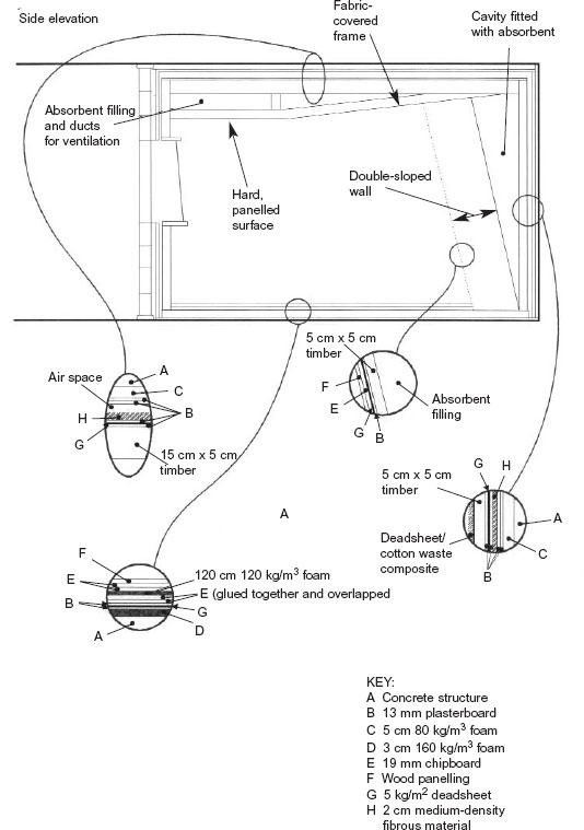
Figure 8.7 Isolation and acoustic treatment details of a small ‘Geddes’ room
Essentially, the double slope allows a relatively steeply angled wall surface without undue loss of floor space, although this is all in relation to the room size. The steep angling tends rapidly to steer the modal energy into the oblique form, which passes round all six room surfaces. Remember, on each contact with a wall, a sound wave will loose energy by absorption, and that absorption tends in many cases to be greater for waves striking the surfaces at oblique angles than for perpendicular impacts. By making all surfaces absorbent, other than the glass, the wooden floor, and the double-angled wall, the modal energy can be suppressed very quickly.
Figure 8.8 shows the room in typical use with Control room 2. In this situation, voice replacement work is being done. The person speaking, or singing, is facing the double-sloped wall. The wall is panelled with wood strips to add life to the room, and into it has been recessed a monitor television for voice synchronisation. The whole wall is hard, but only little reflected energy reaches the vocal microphone, as the window behind the vocalist is angled steeply upwards into the absorbent ceiling. What is more, when the room is being used in this way, it is often desirable to draw curtains across the window. This gives more privacy between the two studios, and the curtain, if heavy, and deeply folded, also helps to suppress reflexions. The double-angled wall is of a relatively lightweight construction, and the whole cavity behind it is filled with mineral wool and scraps of felt and deadsheet, which press against the rear of the wall to provide considerable damping. The cavity itself is heavily damped by the filling.
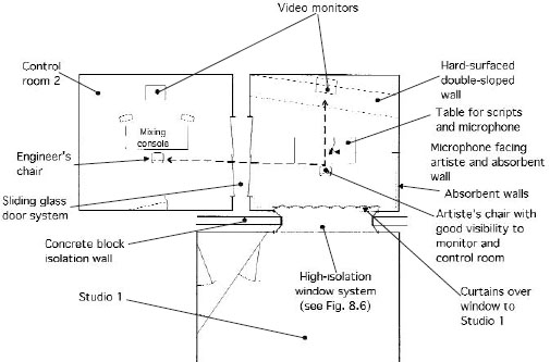
Figure 8.8 Studio 2 in use for voice-overs
If we now consider this room, one frequency band at a time, we will see how the overall design is effective for wideband control. Due to the overall geometry, the mid and high frequencies can find no simple, effective, reflective path back to the microphone. The upper and mid-range of the low frequencies, for which the angling of the window may be insufficient, do not ‘see’ much of the sloping wall, but either pass through into the great depth of absorbent filling, or are absorbed by the highly damped nature of the wall structure itself. The very low frequencies are in the pressure zone of the room, so are in any case rapidly lost. The pressure zone frequency for this room is about 65 Hz. Visibility between the engineer and vocalist is good. Each can face their own monitors, and with just a small turn of the head, can see each other clearly.
In the case of the room being used in conjunction with Studio 1, the musician(s), in this case let us presume that it is a drummer, will face away from the double-sloped wall. This will give direct visibility to Studio 1, and on through to Control room 1. There is also excellent visibility to Control room 2, in the event that it should be being used as an additional isolation room. This situation is shown in Fig. 8.9, and it can be seen that the microphones around the drum kit are generally pointing backwards and downwards. They are thus pointing not only at the drums, but on towards the reflective floor and double-sloped wall, and hence will pick up a great deal of early reflected energy which will ‘fatten’ the sound of the drums. The drum kit will not sound the same as a kit recorded in a live room, nor of one recorded in a large room, but it will certainly, for almost all purposes, be preferable to the recording of a kit in either a more conventional small room or in a dead room. There will be a more potent drum sound and more ‘feel’ for the drummer than would be the case in a small dead room, and only very low levels of unnatural room colouration would result. The room does not possess the small-room boxiness which spoils so many recordings, and in fact, after the first year of use, the studio’s engineers reported that this room was both very well liked and very well used.
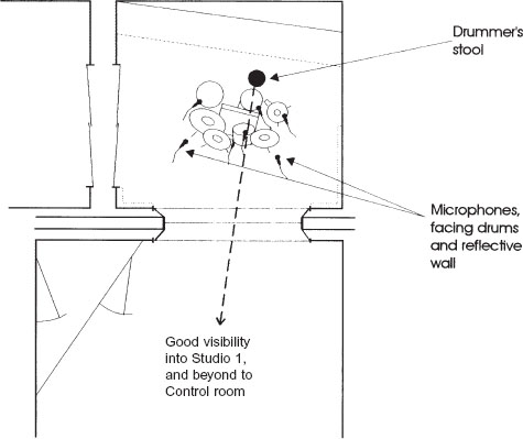
Figure 8.9 Studio 2 in use in conjunction with Studio 1
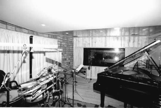
Figure 8.10 Studio room, live one end, dead the other (Tcha Tcha Tcha Studios, Lisbon, Portugal)
8.5 Recording techniques for limited acoustics
In the small studio complex depicted in Fig. 8.4, the main recording area was relatively live, having windows to Control room 1 and to Studio 2 on two of its sides (its two ends), and a large window to the outside on another side. This wall was of angled brickwork installed in a sawtooth arrangement, see Fig. 8.10, and faced a dead wall on the other long side of the room. The floor was of wood, over which rugs could be laid if required, and the ceiling was V-shaped, being hard at the side nearest to the control room, and soft at the Studio 2 side. The room contained a grand piano, the open lid of which could face the hard surfaces if a rich tone was called for, or could face the absorbent ‘trap’ wall if more separation was needed, such as when recording a jazz quartet or similar.
In this room, other than by laying down rugs or using movable acoustic screens, there was little variability provided, as the owners deemed the range of rooms that they had to be sufficient for all of their normal needs. Because they had insisted on such high degrees of sound isolation, in which weight and space were consumed, they did not want to lose any further space by the installation of systems of variable acoustics. Subsequently, however, the ceiling of the live area was made to be more absorbent, because in the state shown in Fig. 8.10, it proved to be, not surprisingly, excessively lively. Nonetheless, skilful use of the spaces is now rendering good recordings, and there are ways to get around the limitation of fixed acoustics.
8.5.1 Optimum use of space
In Section 3.2.1, I referred to a recording which involved the replacement of five acoustic guitars on a live TV recording, destined later for CD release, though not originally intended for such purposes. In the replacement process, in a relatively live room, all the guitars were recorded sequentially in the same spot in the room, and although the room sound was not unduly evident on each track, when the five guitars were mixed together, the room sound was rather too much, certainly for my liking. There is, however, an interesting way of avoiding this, which involves moving the guitars to different room locations, so that each one carries a different ambience, not only due to the collection by the microphone of different reflexions, but also because the room is driven differently, from different nodal and anti-nodal points. This way, not all of the same room resonances are generated, so the tendency for an overpowering build-up of any particular resonance is reduced. In fact by moving the instruments and the microphones in this way, each will add its own variability to the sound. Nonetheless, whilst this can avoid an unnecessary build-up of resonances and can be a very effective technique, it still adds to the phase confusion, characteristic of the use of multiple microphones in ambient spaces. In exposed cases though, if something more akin to a simultaneous, stereo-pair recording is required, there is an interesting way to simulate this.
8.5.2 Moving musicians
There is a technique for multi-tracking vocals which I first heard of when in the USA. Its principles are so obvious when you know about them, but there again, such is the case with many things. Figure 8.11 shows a stereo pair of microphones in a room with an appropriate ambience. If it is desired that two vocalists build up the sound of ten, by means of five unison or harmonised recordings, then instead of grouping them around a single microphone and panning the different tracks into different locations on the stereo mix, a single stereo pair of microphones can be positioned at the chosen spot in the room. The vocalists then move into different locations for each take. If ten recording tracks are available for this, each stereo pair would be panned left and right in the mix, or to whatever other desired position, and the spread of panning would be built up automatically. Usually, the sound of such recordings is much more spacious, powerful, and natural than the ‘five panned mono tracks’ approach. If ten tracks are not available, then, especially if digital recorders are used and noise build-up and generation loss are not problems, each subsequent recording can be mixed with the playback of the previous recordings, carefully balanced of course, and recorded onto another pair of tracks. The previous pair of recorded tracks can then be used for the next ‘bounce’, and so forth. This way, only four tracks are used, and anything which may be needed to ‘repair’ the final build-up such as earlier takes which are now considered to need reinforcing, can be recorded separately on the last but one pair, and either bounced again, or left separate until the final mixdown. There is no extra ambient build-up by the use of this technique, as no extra energy is driven into the room by recording five pairs of vocalists separately than would be supplied by ten vocalists singing simultaneously. It is a technique worth trying, believe me!
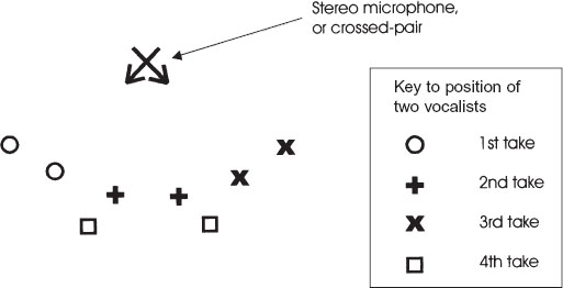
Figure 8.11 Method of creating a more natural ambience when multi-tracking backing vocals. This technique can create a better choir effect than merely panning voices which have been recorded in a fixed position
8.5.3 Changing microphones and positions
Techniques such as these can greatly improve the flexibility of rooms in which the quantity of acoustic variability is not great. Another possibility is to change microphones for different overdubs. If other microphones can be used which are still considered to be acceptable sounding for whatever is to be recorded, then as each microphone type has a distinctive and different polar pattern/frequency characteristic, the build-up of the room artefacts, by multiple recordings in the same place, can be significantly reduced. There are limits however.
8.5.4 Phase
I recall in the mid-1970s being asked to record David Bedford and Mike Oldfield, playing organ and guitar respectively, in Worcester Cathedral in England. This was only four days before the old organ was due to be dismantled. Despite being the technical director of The Manor Mobiles at the time, I used the Rolling Stones’ mobile for the event, as The Manor units had other work on that day. (It was Virgin Records’ policy never to turn down an outside client for the sake of an in-house project. Your own work could be ordered to return to your own studios, but if an outside client went to another company because you could not accommodate them, then they may stay with the other company for future work. This was considered to be bad for business.) Anyhow, the Rolling Stones’ mobile had good staff, good sounding equipment, and an excellent set of microphones, so I felt no loss in being deprived of my own units.
Mick McKenna and I spent a great deal of time, during the rehearsals, walking round the cathedral, listening to the majesty of the sound in different locations, then discussing the most appropriate microphones to use for each location. All in all, we positioned 22 microphones in different locations, hoping to take best advantage of the sounds of each of the sections of organ pipes in the natural reverberation of the cathedral. Each microphone was fed to a different track of the 3M 24-track machines, and once each channel had been assessed for its individual sound during the afternoon rehearsal, Mick stayed in the truck, looking after levels, and I went into the cathedral to savour the atmosphere. As it went dark, the only light in the cathedral was from two candles, one on the organ console, and one on the 100-watt Marshall guitar stack at the opposite end of the cathedral. The music was appropriately named ‘Instructions for Angels’.
It soon became very eerie, but as I wandered around in the dark, this somehow intensified the music. I kept getting frights when approaching the many life-size statues dotted around the cathedral, but finally found a comfortable stone block on which to sit whilst I absorbed the music, though still with a prevailing sense of unease. Eventually, we were thrown out by the police. It was getting very late and it appeared that we were keeping half of Worcester awake. The sound isolation in these buildings is not what it could be! When the dim electric lights came on as the police arrived, I had another sudden fright when I found that I was sitting on the tomb of King John: perhaps something that Robin Hood would have rather enjoyed rather more than I did.
The following week, I went to the private studio of Mike Oldfield to begin mixing. The album was scheduled as Virgin’s first release using the BBC ‘Matrix H’ quadraphonic coding system, and Mike’s studio had a set of Eastlake Audio, quadraphonic monitors. I listened to the various tracks of the multi-track, pair by pair in the front or rear loudspeakers, or, at times, a pair on each front/back side. It was really impressive and I played around for hours. Time was of no consequence; it was a private studio and was not being charged by the hour. Eventually, out of the 22 microphones recorded, I decided to use about ten. Then, horror struck.
When more than three or four microphones were brought into the mix, they were usually destructive. The phase relationships simply would not add. Nor, in fact, would they subtract overall. They were entirely random, and no amount of phase changing could make things work. Of course, I knew this in principle and immediately recognised what was happening, but I had never had the problem quite so startlingly presented before me. In stereo, the destruction was even worse, and it was so intensely frustrating because I knew what amazing sounds I could imagine by listening pair by pair, or even with pairs of pairs. In the end, many of the separate microphones were put to good use, as for example when the organist changed from the choir organ to the swell organ, or the great organ to the main. Edits could be made in the mix, changing at the appropriate time to pairs of microphones considered to be most rich or revealing for each section of the music. Unfortunately though, the magic sounds that I could build in my imagination could not be built acoustically.
I knew exactly why I could not have what I wanted in the mixing of the microphones, and I knew that it was pointless even trying to get what I wanted from them, but I remember that it took me a very long time to accept the fact that I would just have to live with my frustrations. It took me back to the early days of 16-track, when the use of multiple microphones on drum kits was beginning to grow in popularity. Producers and engineers would get some very crisp and powerful tom-tom sounds, then go mad when they heard their wonderful sounds played back from the analogue 16-track machines. As with the sounds in the cathedral, it seemed like the better the sounds you began with, the more they were spoiled. We would, as a matter of course, call in the maintenance engineers to check the alignment, but they usually put a square wave into the machine and showed us on an oscilloscope display a total travesty emerging. We realised that the inherent phase shifts of analogue recording could forever limit us from hearing recordings of the sounds which we heard on the monitors, directly from the studio.
I was never quite sure whether it was something in the ‘magic’ sounds which the analogue recorders (or tape) could not handle, or whether it was the greater sense of loss at not being able to faithfully record the best sounds, that always seemed to me to be the reason why those sounds were the ones most noticeably destroyed. Then again, when digital recording should have solved this problem, no matter what was the cause, people began to complain that the digital recordings lacked the ‘glue’ that held the whole drum kit together, and often reverted to analogue machines for drum recordings. So was digital the magic word? I think not. It seems that every instance must be judged in the light of its own circumstances, and that absolute generalisations are difficult to make. Unfortunately, that over-used word ‘compromise’ rears its head all too frequently.
Possibly we should end this chapter with a look at a compact studio, where acoustic variability was needed, along with a good degree of separation. The studio was built in London, and was for commercial use. Its owner was a drummer, and, not too surprisingly, drum sounds had a strong input into the design considerations. Nevertheless, there was also great importance put on vocal recordings, and electric guitars and basses. Figure 8.12 shows the overall layout. The main studio area is subdivided by hinged panels which have hard surfaces on one side and soft, absorbent surfaces on the other. The whole studio is situated in a warehouse, with relatively few problems caused by a small amount of escaping sound. It is not on a main road, so the low frequency rumble of fast, heavy traffic is no problem either. A controlled leak of low frequencies was allowed to pass into the warehouse, thus preventing excessive build-up in the smallish rooms.
Drums can be recorded in the main area, in an acoustic ambience of whatever liveness or deadness that the room can provide with its variable states. Separation for guide vocals or other instruments can be achieved by creating booths out of the hinged partitions. Outside of the main recording area, and separated from it by a corridor, is a separately floated box, containing three small booths into which can be placed guitar or bass amplifiers, fed from instruments in the other rooms via line amplifiers. The musicians themselves can be located in the main studio, or the control room, which can also house keyboards and their attendant musicians. Once the rhythm tracks have been laid, the main room can be reconfigured for the recording of acoustic guitars, lead vocals, backing vocals, or anything which may be required for completion of the recordings. This is yet another approach to the concept of a multi-room studio with a combination of acoustics.
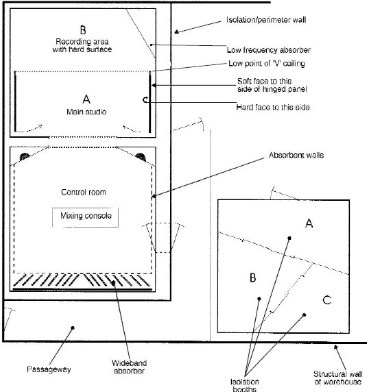
Figure 8.12 Studio in a warehouse, with external booths. With the hinged panels in the positions shown, the whole of area A/B becomes one, large live room. When the panels are swung out to the dotted line, section B remains live, but in section A, soft, absorbent surfaces become exposed, rendering the acoustic in that area much more dead. Panels can be moved individually, or partially, to change the sound or to use them as screens between instruments. The doors are quite heavy, with wheels supporting their outer ends, so isolation between sections A and B is quite reasonable when the doors are swung out to the dotted line. The ceiling is an inverted V-shape, with its apex above the dotted line. Over area A it is absorbent, and over area B it is finished with wooden panels.
The isolation booths, intended for high level recording of bass or guitars, are well isolated from the main studio and control room. Booths A and C are acoustically rather dead, whilst booth B is relatively live. Sliding glass doors are used to maximise the usable floor space. With windows in the control room entrance doors, and in the side wall of booth B, visual contact between the engineer and booths B and C could be provided.
If such a warehouse were not in a noise-sensitive location, the walls could be relatively lightweight, allowing a controlled leak of low frequencies, and thus giving the rooms better LF performance without the use of too much internal LF absorption. With a lighter weight construction, costs can also be greatly reduced
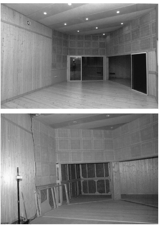
Figure 8.13 Dobrolyot Studio, St Petersburg, Russia
(a) The form of a ‘village’ within the building
(b) The view from the stone room into the vocal room which can be fitted with curtains when necessary
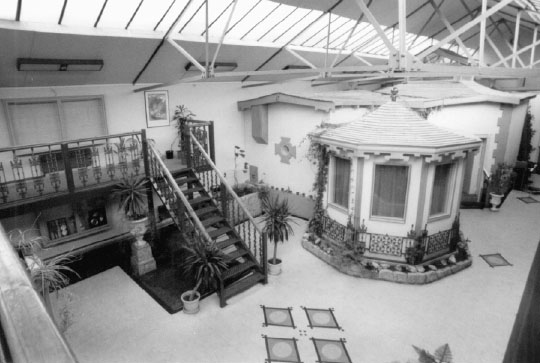
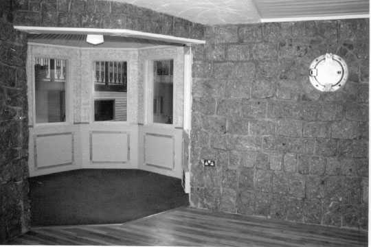
Figure 8.14 The Pink Museum, Liverpool
Figures 8.1, 8.4 and 8.12 show three actual, workable, successful, but very different methods of tackling the problem of how to combine different acoustic options. The range of possibilities is almost endless, but these three examples give a feel for three very dissimilar approaches which could be variously adapted and modified to fit a wide range of likely starting conditions. Again, however, there are few absolute rules, which is why the experienced studio designers are so frequently relied upon for their expertise. Their function is not only to offer design suggestions, but also to point out things which the clients want, but which may lead to trouble in the future. Such points are not always obvious, and the problems are often only realised after past experience has pointed them out. Hopefully, this chapter will have at least begun to point out the strength of certain concepts, together with the weaknesses of others. As it has progressed, we have been able to look at some of the decisions which have had to be made along the way. One thing is for sure, however; the permutations are endless.
As a final point of possible interest, the rebuilt version of the aborted attempt to construct the studio, as depcited in Fig. 8.2, is shown in Fig. 8.13. The studio now incorporates a wooden live room, an acoustically dead vocal room, and a moderately large general studio area with reflective, absorbent and diffusive walls, not too dissimilar to the ideas outlined in Fig. 2.19. It works well, and the owners are very pleased with the results. It also ended up costing far less to build than the $50,000 which had already been spent on the originally proposed design.
The idea of a whole concept is illustrated in Figure 8.14. As shown in Fig. 8.14 (a) the studio takes the form of a ‘village’ within a building. The hexagonal room in the foreground is a vocal room which leads off a granite live room. The main neutral recording room is beyond, with skylights rising above it. At the back, with an external entrance on the extreme right of the photograph, is the control room. The balcony, from where the photograph was taken, has facilities for the preparation of food and drink, and also incorporates a lounge area with satellite television projected on to a large screen. The idea behind the design was to take the musicians into a self-contained space, isolated from the outside world, in which they can relax in absolute privacy. Despite the sense of spaciousness and tranquillity it is less than 30 m from a busy commercial street with shops and many restaurants of different ethnic origins.
References
1 Zenon Schoepe, ‘Galaxy’, Studio Sound, Vol 36, No 10 pp 42–44 (October 1994)
2 Earl Geddes, ‘Analysis of the Low Frequency Sound Field in Non-Rectangular Enclosures using the Finite Element Method’, PhD dissertation, Pennsylvannia State University, USA (1982)
3 Philip Newell, ‘Studio Monitoring Design’, Focal Press, (1995)