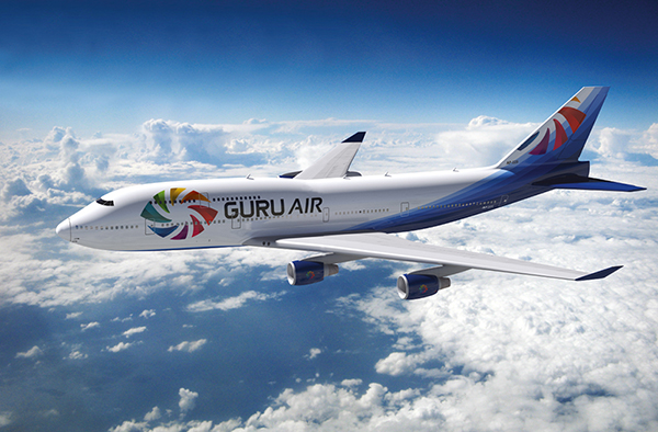
![]() Inspired by the many TV adverts for airlines, I wanted to create a classic over-the-clouds shot on an airplane. I used the name Guru Air, based on my website (blenderguru.com). It was my first serious attempt to create an airplane, and it took around four days in total.
Inspired by the many TV adverts for airlines, I wanted to create a classic over-the-clouds shot on an airplane. I used the name Guru Air, based on my website (blenderguru.com). It was my first serious attempt to create an airplane, and it took around four days in total.![]()
| PROJECT | BOEING 747-400 |
| SOFTWARE USED | BLENDER, PHOTOSHOP |
| RENDERING TIME | 8 MINS. 4 DAYS TO CREATE |
| ARTIST | ANDREW PRICE |
| COUNTRY | AUSTRALIA |
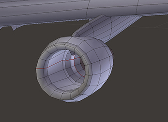
The engine was surprisingly easy to model – just a solid cylinder. I didn’t bother with the inside motor as it isn’t viewable from the camera.
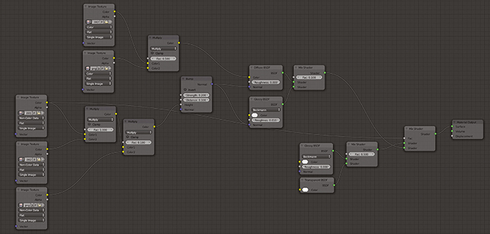
This was the final node layout in Blender for the exterior material. Lots of custom textures were overlayed on top of each other.
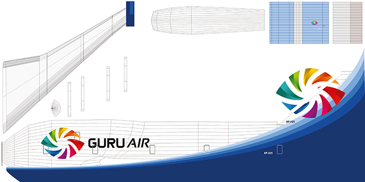
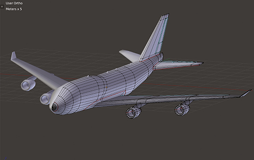
The finished wireframe. The entire plane was mirrored to save on modelling so only half had to be created.
| PROJECT | NORTH HUNTER |
| SOFTWARE USED | BLENDER 2.65 |
| RENDERING TIME | 2 HOURS |
| ARTIST | ANTOINE MOREAU |
| COUNTRY | FRANCE |
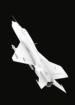
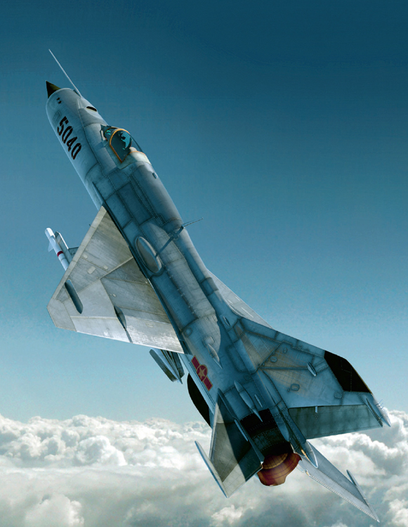
![]() A Vietnamese Mikoyan-Gourevitch Mig-21 is finishing its manoeuver in the north sky. When I was a young boy, I dreamed about fighters. I tried to draw some of them but I was finally able to get what I wanted using 3D software. I modelled this one in Blender using very classical polygonal modelling. It is composed of distinct objects: fuselage, cockpit, seat, pilot, missile, etc. Each object has its own UV mapped textures drawn using Photoshop which include a colour map, one or two bump maps mixed in Blender nodes and a reflective map. I painted the clouds using a photo reference over a ground and painted the top part of the blue sky.
A Vietnamese Mikoyan-Gourevitch Mig-21 is finishing its manoeuver in the north sky. When I was a young boy, I dreamed about fighters. I tried to draw some of them but I was finally able to get what I wanted using 3D software. I modelled this one in Blender using very classical polygonal modelling. It is composed of distinct objects: fuselage, cockpit, seat, pilot, missile, etc. Each object has its own UV mapped textures drawn using Photoshop which include a colour map, one or two bump maps mixed in Blender nodes and a reflective map. I painted the clouds using a photo reference over a ground and painted the top part of the blue sky.![]()
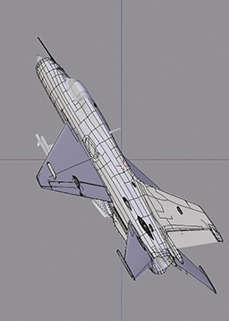
Constructing the MiG-21 using distinct objects to make up the shape and the surface features.
The ambient occlusion pass. Used when compositing the image with the background in Photoshop.
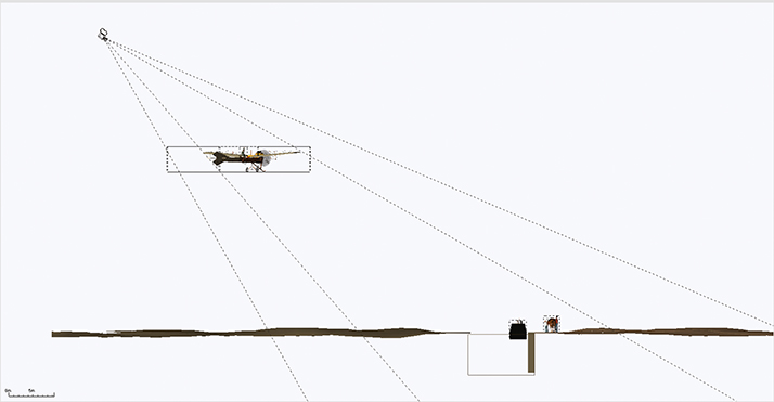
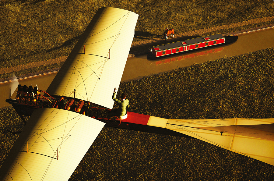
![]() The Antoinette was one of the most graceful pioneer aircrafts. Powered by a V8 engine, one almost crossed the English Channel a few days before Bleriot flew into the history books. I wanted to depict an aviator waving to people who may never have seen a flying machine before, and the impact it would have made on them. Early planes often navigated by following roads or railway tracks, and rarely flew very high – in 1910 it was an Antoinette that set a new world altitude record of 510ft.
The Antoinette was one of the most graceful pioneer aircrafts. Powered by a V8 engine, one almost crossed the English Channel a few days before Bleriot flew into the history books. I wanted to depict an aviator waving to people who may never have seen a flying machine before, and the impact it would have made on them. Early planes often navigated by following roads or railway tracks, and rarely flew very high – in 1910 it was an Antoinette that set a new world altitude record of 510ft.![]()
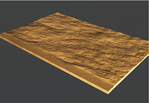
I started with a generic terrain, and flattened a strip down one edge.
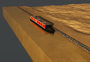
The narrowboat is a collection of blocks and simple shapes, the canal is another block with a suitable water texture applied.
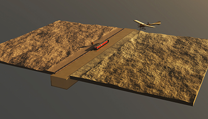
When all the pieces were assembled, it was like making a virtual train set.
| PROJECT | THE EARLY BIRD |
| SOFTWARE USED | 3DS MAX, VUE 9 |
| RENDERING TIME | 14 HOURS |
| ARTIST | STEVE KERRY |
| COUNTRY | ENGLAND |
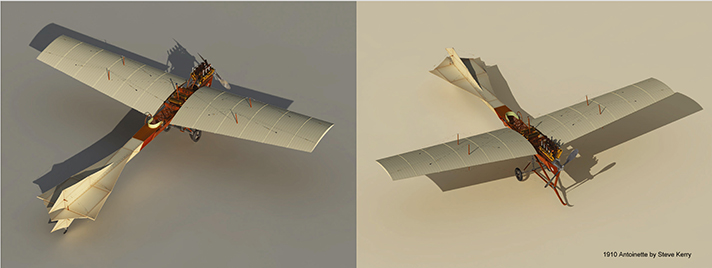
I made the Antoinette model a while ago, as an exercise in modelling and texturing.
MODEL AND TEXTURE THE SPACE SHUTTLE
Nicholas McElmury explains the process of creating the icon space vehicle
BEHIND THE SHUTTLE
I built this for a mini-challenge at CGSociety. I’ve always been a bit of a space geek, so when I saw they were doing a NASA challenge, I couldn’t resist. I was fortunate enough to see a couple of shuttle launches and tour the Kennedy Space Center a while back. I can remember being so impressed by the scale and precision of everything that went into launching a vehicle into space. Since the program is grounded now, I thought it would be a good homage to the end of such a great era in space travel.
For the final image, I wanted something realistic, but a little more pleasing to the eye than a typical launch photograph. I took great care to make everything as true to the actual shuttle as I could, including all the small panels, heat shielding, engine details, escape hatches and even the dirt patterns on portions of the body.
I wanted to capture the power of a launch, from the actual size of the shuttle, the distance it’s travelling and the massive amount of heat given off by the boosters as they burn through their fuel on the way up.
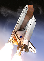
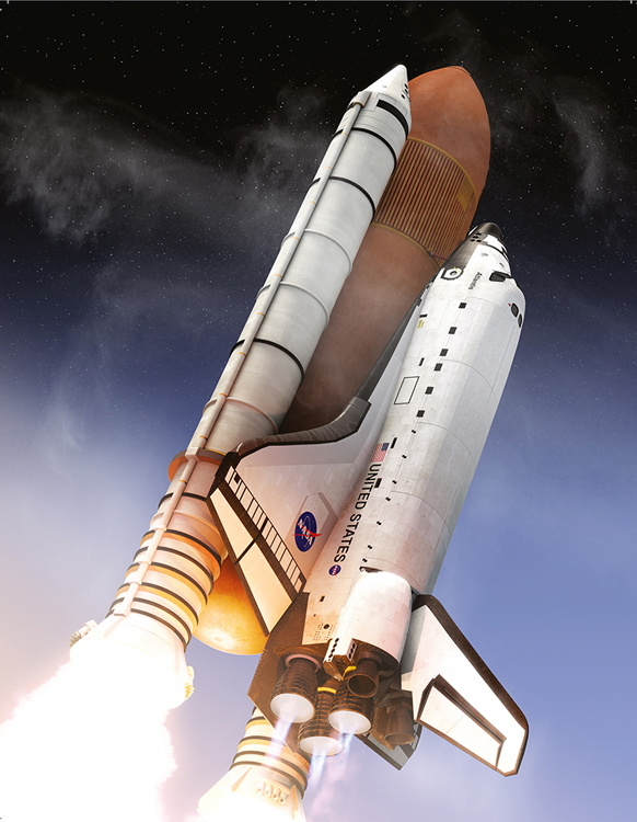
Space Shuttle Atlantis – final image
| PROJECT | SPACE SHUTTLE ATLANTIS |
| SOFTWARE USED | 3DS MAX, V-RAY, PHOTOSHOP |
| RENDERING TIME | 20 MINUTES |
| ARTIST | NICHOLAS MCELMURY |
| COUNTRY | UNITED STATES |
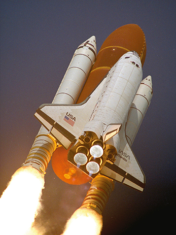
This photo is a good representation of the heat the rockets give off when they are at full power.
The modelling process was the most time consuming and intense portion of making this. At first glance, it seems like it would be a fairly simple model, but upon looking a little closer at the reference I had grabbed, I realized it was full of small details.
Over the past few projects I have done, I’ve realized the more you can model, and the more detail you put into the model, the better it will look. When working with larger objects this is especially important. The contrast between the small details on the model in relation to the model as a whole will make the large size much more apparent. Scene scale is also important; I built this to 1:1 scale, so it was helpful to be able to measure parts of it to make sure I wasn’t modelling anything that would be disproportional.
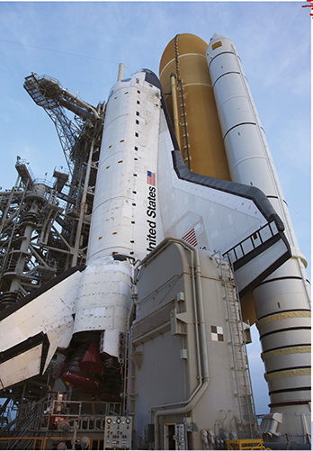
I can’t overstate the importance of using quality reference for modelling objects like this. I was fortunate in that NASA has a library of thousands of high resolution images I was able to pull from.
To start, I blocked out the shuttle as a whole in its basic form. I usually use a retopology workflow, so in the beginning, I wasn’t especially concerned with proper edgeflow.
This is the photo that really inspired the sense of scale and power that I wanted to portray.
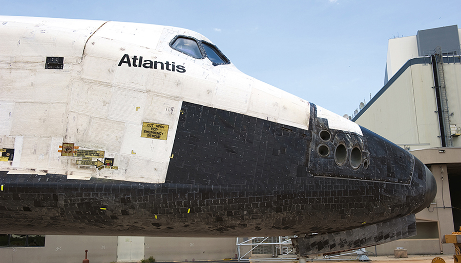
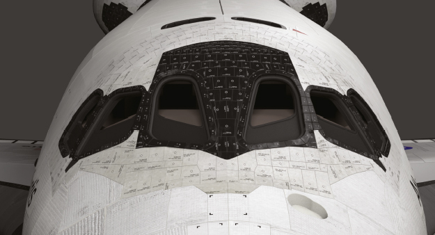
This photo shows a lot of the details in the panels that cover the ship, also just how dirty and worn the shuttle really gets. Notice the streaks covering the nose.
This shuttle is covered in small panels, so I used 3ds Max’s graphite tools, namely the Freeform PolyDraw tools, to map out most of them. It took some serious time, but I wanted to make it as accurate as possible. I placed them directly on the base mesh I had made and built them in blocks.
For the white panels, I cut directly into the base mesh and bevelled accordingly since they had a tendency to wrap and conform to the curves of the shuttle. Some of the stickers were modelled as well, more for the sake of making the texturing process easier than anything else.
Certain portions of the shuttle are covered in rivets and bolts, though they are basic, I decided it would look best to place them in the proper spots to give it the amount of small detail I was aiming for.
One important thing to note when making vehicles that have windows – it is always a good idea to build an interior, even if you won’t be able to see much of it. I found some references of the flight deck and built a basic shadow interior. When viewing it from certain angles it’s nice to see some shapes refracted in the glass and gives it that much more believability, even if it’s just low poly filler objects.
Nearly everything on this model was bevelled so the light would have a nice edge to reflect from. For certain larger, more visible edges, the triple edge technique was used which is great for rounding corners with minimal effort and polygons. This technique will usually hold up with a smooth applied to it as well, though sometimes it’s not necessary.
The boosters and rockets were made from basic shapes, cylinders and capsules with the proper faces extruded and details cut in.
Here’s an example of all of the panels that were modelled. Since I wasn’t smoothing the main fuselage, I wasn’t too worried about having long triangles.
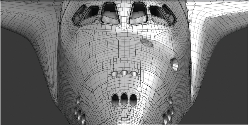
The front end where the flight deck resides. Most of the large panelling was built to smooth. You can see the basic interior that was created.
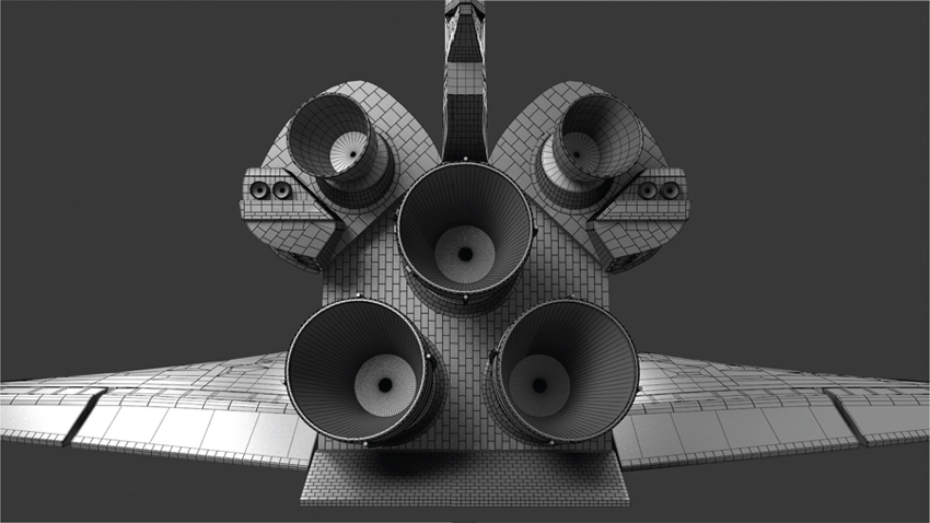
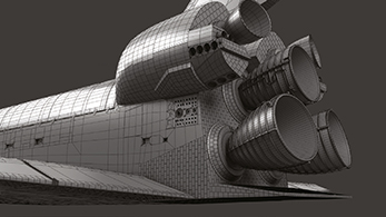
The back of the spacecraft. I knew the engines were going to be spitting out fire, so I didn’t spend much time modelling the interiors of the rockets.

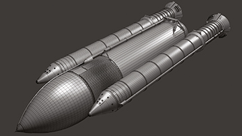
Wireframes for the fuel tank, rocket boosters and supports. The basic shapes were easy, the devil was in the detail.
Texturing and shading has always been one of my favourite parts of the process. The space shuttles actually get quite dirty and have lots of small scuffs and wear marks on them, so I wanted to make sure they were represented properly and where they would naturally form.
A combination of file textures, procedural textures, composite maps and shader effects were used to get the final look of each piece.
The hard panels were textured with two painted textures, a V-Ray dirt map, and a noise map all built into one composite texture. All the panels had a lighter colour at the points where they meet, so I used the V-Ray dirt map to achieve this effect easily and relatively cheaply. A faint noise map was added on top of everear and tear. Around the nose, streak maps were painted that were overlaid as well using a separate UV channel to precisely place them.
The soft white panelling was textured with two image textures. I cropped a few different- looking cloth panels onto the same texture sheet, and was able to unwrap the portions and place them on the texture wherever they looked best. This sped up the process quite a bit, allowed me to keep the resolution high on smaller pieces, and was topped off with a painted dirt map that encompassed all of the white panels on a separate UV channel to give them the needed variation.
For the white cloth panels, a falloff map in the diffuse slot was used with two versions of the diffuse texture; a darker one for faces pointed towards the camera, and a slightly lighter version of it that appears as the faces wrap away from the camera. This gave it a nice, soft, cloth- like effect.
The V-Ray Material was used for all of the materials as it gave the most control over reflections and refractions across the model.
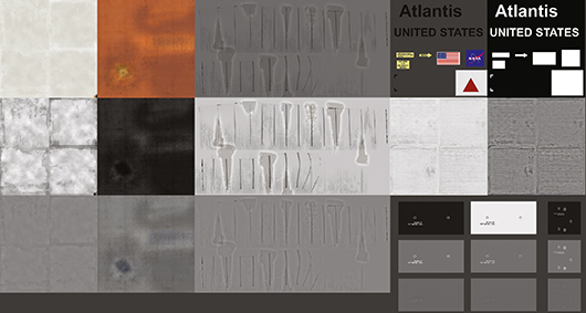
Below are a few of the maps that were used. On hard surfaces, I made sure to make colour, spec and bump textures for nearly everything.
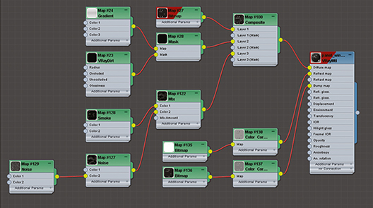
I generally work with composite textures a lot. They work well in conjunction with multiple UV sets and this way you can layer anything you want across multiple resolutions.
Some procedural and painted textures were used to make some scuffs to the front. The painted- on details (emblems, stickers, etc.) were all done with composite textures and UV sets.
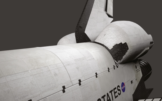
Here is a shot of the back. The shuttles actually have a lot of grime on them.
The lighting for this was probably the fastest, simplest part of the whole process. I wanted a nice daylight along with some light to show the heat from the rocket fire.
A standard directional light with V-Ray shadows for the sunlight illumination was used, coupled with a V-Ray dome light to simulate the bounce light.
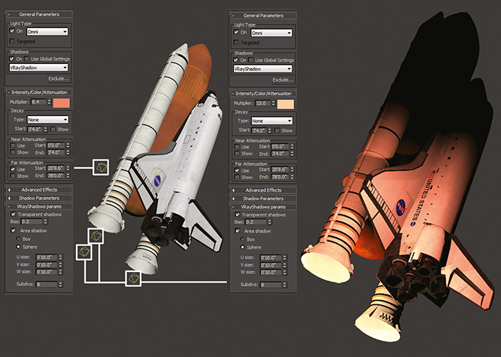
For the rocket fire illumination, a series of omni lights with a hot orange and red colour were used to light up the shuttle where it would be receiving light from the fire. These all had attenuation set so the light would fall off nicely across the model as it got further and further away from the heat source. They also were all using V-Ray shadows.
One important thing I always try to do is to work with gamma correction turned on and set to 2.2. You could spend hours dropping in lights and trying to place them to get an even look of illumination across your entire model, but setting your gamma properly makes this much easier to achieve, saving you loads of render time.
Along with setting your gamma to the proper settings, using proper exposure control and camera settings will also make your lighting process a little easier.
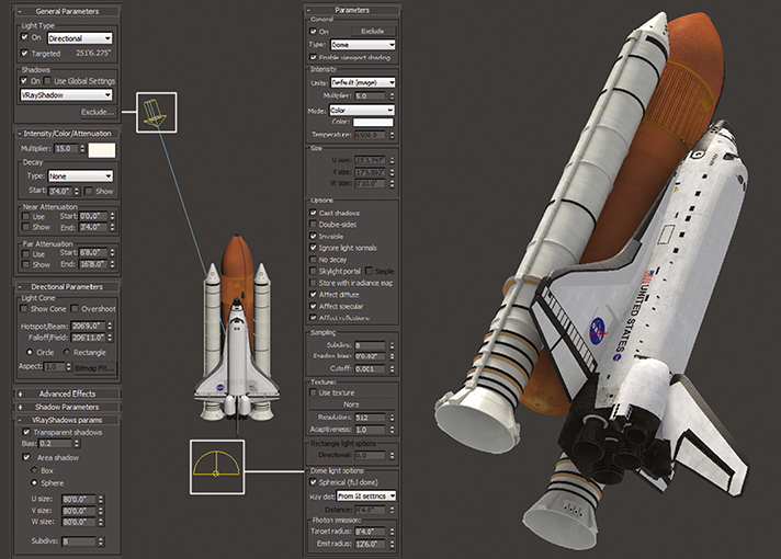
Here is the placement and the settings for the daylight and sunlight in the viewport and the resulting render.
TOP TIP – TRIPLE EDGE TECHNIQUE
For hard angled edges, instead of using a chamfer, use a triple edge. These are supporting edges that don’t deform the model and lie close to the angled edge. In 3ds Max, select an edge, and hit extrude, keep the height at 0, and adjust the width. Use smoothing groups (soft edges) to blend over them. They will also hold up better than a standard chamfer when you apply a smooth.
V-Ray was used for the rendering and took about 20 minutes to render out the complete image fully. For the daylight pass, I kept GI off for this render, as all it would do was increase the render time.
When you’re rendering with V-Ray, it’s important to understand how the sampling engine works. Fine tuning the adaptive image sampler and the DMC sampler along with a sample rate render pass can really help your render times.
As far as render passes, the main daylight pass, a pass for the glow from the rocket fire, a V-Ray dirt pass (ambient occlusion), a sample rate pass (for testing) and an object ID pass were rendered to create separate elements making it easier to combine them later on in Photoshop.
A V-Ray camera was used to render from and it’s settings were adjusted to the exposure that I wanted. Since images of the shuttle at high altitude require a long lens, I set my focal length to 280mm, and my film gate to 24mm to get a nice look. For the exposure, I kept the f-number at 8, set the white balance to pure white, and set the film speed (ISO) to 100.
When I render out of 3ds Max, I try to get everything as close as is possible to the final look I want, instead of relying on extensive post processing. I find it easier to achieve the look I want this way, instead of layer upon layer of colour correction operations.
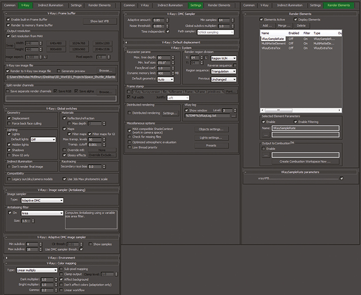
Here are my render settings. Everything is mostly default, with the exception of 2.2 gamma and tuning the samples along with the noise threshold.
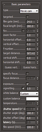
TOP TIP – CAMERA SETTINGS
Try to keep your camera and exposure settings close to real world values – this will help ground your scenes in reality (if that’s what you’re going for). This will also help with lighting your scenes, since you can light based on values set by your camera.
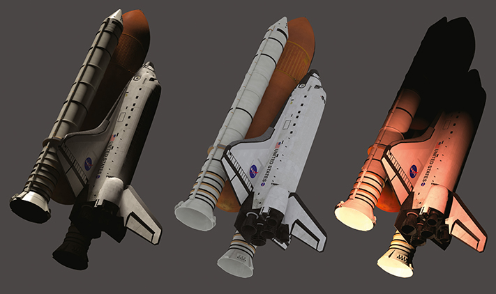
These are the separate light passes, left to right, sunlight, bounce light, rocket lights.
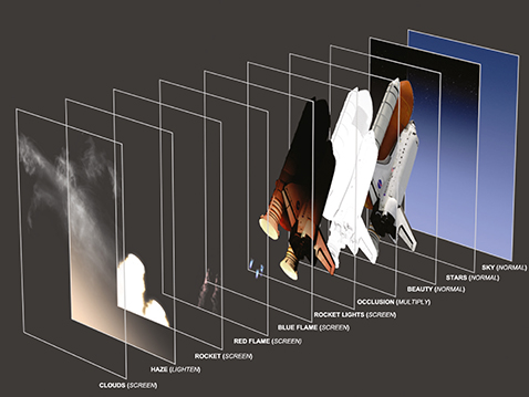
COMPOSITION IN PHOTOSHOP
All the compositing was done in Photoshop. After I’ve rendered out all of my elements, I bring them all into one document in Photoshop and order and name them properly. Keeping clean, properly named layers always helps me work a little faster since I don’t have to guess which layer is which.
Using the multi-matte element also gives you a great advantage as you can isolate certain areas of your image by selecting colour channels and using them as masks.
The main shuttle and engines were all built in 3D, whereas the background is just a simple gradient with a painted star map laid over the top of it. A couple of adjustment layers were used to do minor colour corrections on certain areas of the shuttle, and brightened up some small areas that I wanted to stand out a little more.
The fire and smoke effects were painted using standard brushes within Photoshop with some basic scattering and brush stroke effects applied.
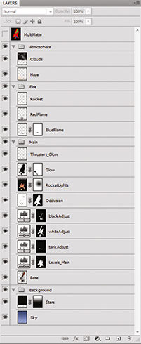
This is the layer stack. You can see the multimatte element sitting on top which I used to create some of the layer masks.