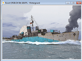
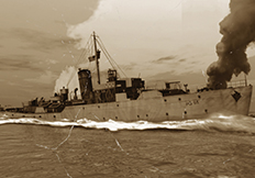
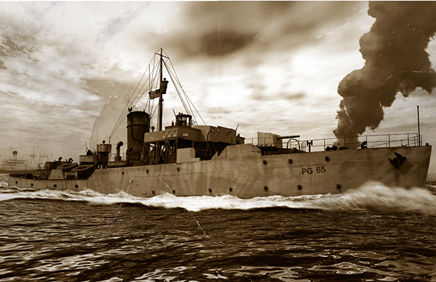
![]() This is the USS Saucy which modelled from scratch using Hexagon. It was then placed in a Vue scene so the rolling waves would be easier to generate. Post production was used to give the image a time-worn, 1940s style.
This is the USS Saucy which modelled from scratch using Hexagon. It was then placed in a Vue scene so the rolling waves would be easier to generate. Post production was used to give the image a time-worn, 1940s style.![]()
| PROJECT | ESCORT |
| SOFTWARE USED | VUE 11 COMPLETE, COREL DRAW 11, HDRI DARKROOM, FILTERFORGE |
| RENDERING TIME | 8 HOURS |
| ARTIST | REINER JORDAN |
| COUNTRY | GERMANY |
The objects were placed in Vue. After that the perspective was set and the atmosphere loaded and edited.

The Illumination was adjusted and a final fine tuning took place in the shadow editor.
Corel Photo-Paint was used to add details such as the sea foam by using motion blur.

To create as much contrast as possible, an HDRI effect was generated in Darkroom 5.
In FilterForge the filter Old Photo was used to create a 1940s style with toning and scratches.
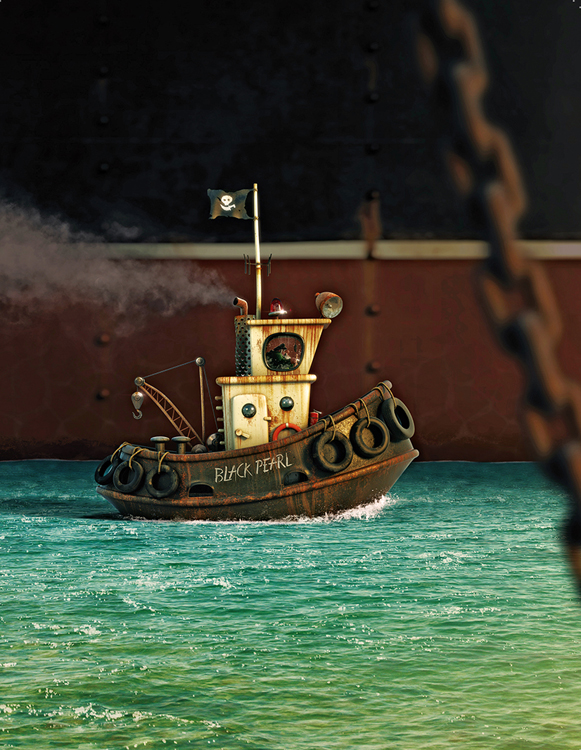
![]() This project was based on the illustration of the great artist Denis Zilber. It shows a little ship, full of character and defiance, with the name associated with those pirate movies, alongside a massive tank, which dwarfs it.
This project was based on the illustration of the great artist Denis Zilber. It shows a little ship, full of character and defiance, with the name associated with those pirate movies, alongside a massive tank, which dwarfs it.![]()
| PROJECT | BLACK PEARL |
| SOFTWARE USED | MAYA, V-RAY, PHOTOSHOP |
| RENDERING TIME | APPROX. 3 HOURS |
| ARTIST | ALEXANDRE TREVISAN |
| COUNTRY | BRAZIL |
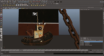
Showing the textures of the boat inside the Maya interface.
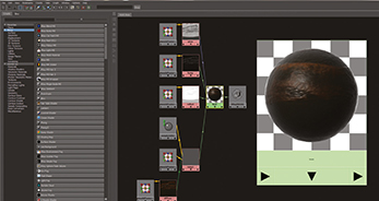
Combining the various elements for the shader for the boat.
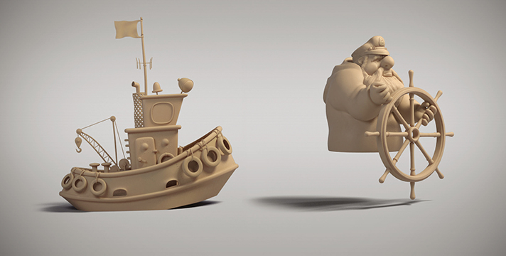
Completed modelling of the boat and the captain in the window.
![]() just wanted to take a look at creating a futuristic seaplane in Vue . This was my first attempt at creating the Osprey Mk1 using metablobs and Boolean intersections. I imagined that it had to have that boat-show shiny and sleek shape. If you have ever dropped your car keys down a drain, then you know how this guy feels.
just wanted to take a look at creating a futuristic seaplane in Vue . This was my first attempt at creating the Osprey Mk1 using metablobs and Boolean intersections. I imagined that it had to have that boat-show shiny and sleek shape. If you have ever dropped your car keys down a drain, then you know how this guy feels.![]()
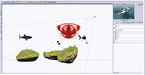
Here all the final elements were being positioned before rendering. I find it easy in Vue to organise the objects in layers.

Finally setting up the camera angle so the scene was ready to render.
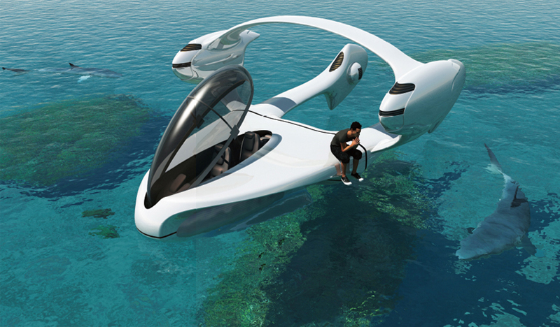
| PROJECT | THE LOST KEYS |
| SOFTWARE USED | VUE 11 COMPLETE, POSER |
| RENDERING TIME | 2–3 HOURS |
| ARTIST | TERRY M ALLITT |
| COUNTRY | UNITED KINGDOM |
LOST AT SEA
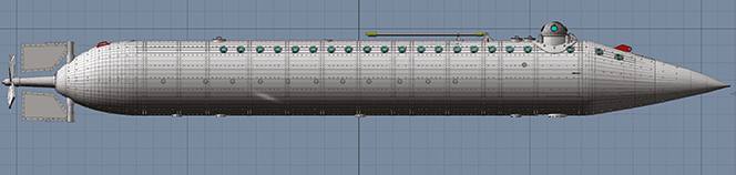
Don Webster explains how he modelled and rendered an American Civil War submarine
HOW THE STORY BEGAN
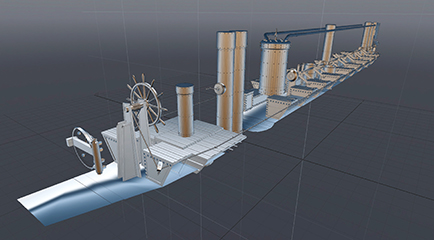
This started out as my first modelling project in Modo as my oldest son, who teaches modelling and animation at VaTech, introduced me to the program and pushed me to start creating my own assets. The effort was based on the continuing research from NOAA on the Civil War vessel, its initial construction in France and refitting in the US. Since research kept updating the interior, the initial composition plan was for an exterior view of the sinking of the vessel during a storm off Cape Hatteras as she was being towed.
The interior was updated as new information became available and except for the removal of the original propulsion paddles, had little effect on the hull itself. The detailing was always based on what would be desired for interior shots, as I was always interested in what conditions would have been like for those who worked inside her cramped quarters.
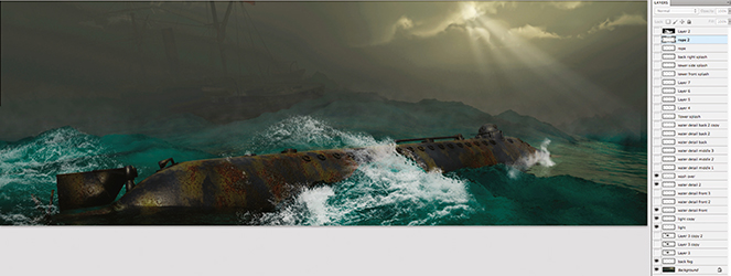
A 40″ framed giclee canvas print of the Loss of the Alligator resides at the Graveyard of the Atlantic at Hatteras, part of the North Carolina Maritime Museum System.
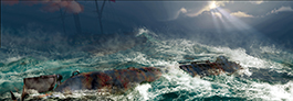
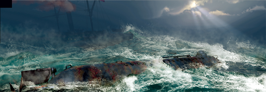
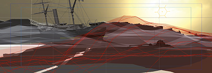
Loss of the USS Alligator – final image

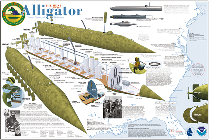
The initial NOAA poster provided the first real information necessary to model the exterior.
| PROJECT | LOSS OF THE USS ALLIGATOR, CIVIL WAR UNION SUBMARINE |
| SOFTWARE USED | MODO, VUE INFINITE, PHOTOSHOP |
| RENDERING TIME | ABOUT 30 HOURS |
| ARTIST | DON WEBSTER |
| COUNTRY | USA |
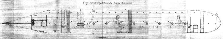
A later poster provided all the necessary information to model the interior. The time span for the information was a number of years.
STEP 1
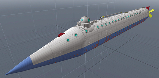
MODELLING THE TUBE
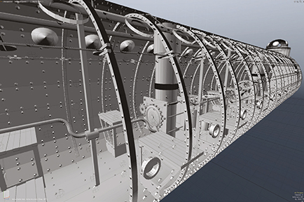
Modelling the hull was a simple process for a new modeller in that it is basically a tube with closed ends. I was intrigued with the idea of hull plates, bolts and rivets, always with the image of what the interior would be like, damp, semi-rusty, dark with beams of light coming into its small portholes.
STEP 2
VERTICAL CUTS
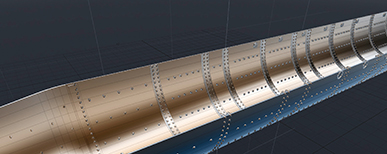
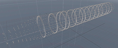
The exterior polygon shell was given a thickness which then allowed for vertical cuts to the interior mesh to form ribs. These small polygon ribbons that now circled the hull were extruded, edges bevelled and made ready for rivets that would protrude through both inner and outer hulls.
STEP 3
ADDING RIVETS
While the rivets could just have been a texture map, knowing that there would be interior views that were at extreme wide angles and point lights that should cast shadows from all these rivets, I decided to model a simple rivet that I could duplicate. A single ring of rivets was created then duplicated for the ribs and repeat duplicated at each rib location. An extra set was created and selected rivets deleted to create the hull plate rivets and the duplicate move-down process repeated.
STEP 4
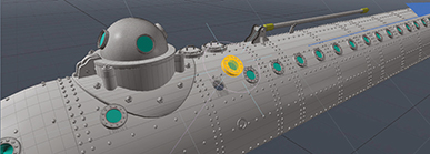
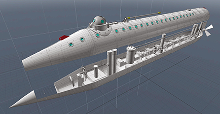
CONNING BUBBLE AND PORTHOLES
There were a lot of openings in the hull that required selecting both the interior and exterior polygons and creating a circular polygon cutting template that was repeated along the length of the hull. This required changing the working plane to that of the polygon surface that was most in-line with the portholes which needed to cut. While in this new working plane, the porthole mechanics and glass windows were modelled and moved into place and again, duplicated and moved to each opening location.
INTERIOR DETAILS, PUMPS AND SEATS
With the latest poster from NOAA, modelling the interior was rather straightforward with simple box and cylinder shapes. The floor was simply a matter of selecting the appropriate polygon edges of one interior wall side and bridging it to the other side. It simply connects the edge of one mesh to that of another. Modo’s tube tool made simple work of the crank handles, and as always, edges are relieved where necessary.
STEP 6
WORKING THE INTERIOR
With the complexity of the interior, it would be difficult to pose figures inside using Poser as well as positioning other items that would have been available and used at the time such as lateens, apples and personal items. The outer hull could have been made invisible, but I elected to have a two-part hull that could be opened.
STEP 7
DIVIDING A HULL
Dividing the hull into an upper and lower half was a simple matter of locating an existing polygon division that runs horizontally along the entire model, selecting all the polygons above it and making it into a separate mesh group. As an asset developer, this also provided a great way to show off the interior for those interested in including it in their collection of modelling assets.
STEP 8
INTRIGUED BY THE POSSIBILITIES
Before moving on to texturing, I took some time to think about what it must have been like to have a number of men in a tube around 5 ft 7 inches tall with little light; the wetness, sounds, and fear of battle while being under the water. I think we forget that many people in past centuries did not swim.
CHOICE OF SOFTWARE
While Modo is a great renderer, I tend to render in Vue since I create models for that community and customers like to see what their purchases will look like in their application of choice. I also lean towards Vue as I prefer its material system, especially glass, water and metal. While Vue is a landscape application, the world environment and atmospherics make it the perfect electronic diorama for creating my scenes.
STEP 9
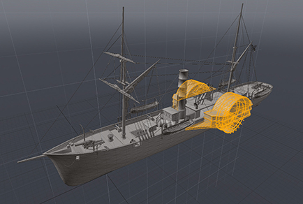
TAGGING MECHANICAL ITEMS
Regardless of whether I use UVs or procedural materials, I colour-assign each mesh that I want to have a particular texture. In Modo, one has to do this to be able to then create a UV file in the system. In Vue this allows easy selection of a mesh, or part of a mesh to assign a procedural material.

STEP 10
ADVANTAGES OF UV AND MATERIAL PRESETS
Metals in Vue are procedural and provide a seamless omni-directional pattern that works well for items like chrome, brass, anything without a directional pattern to it like plate lines. Since procedurals do not work for things like wood objects where the material pattern needs to orient itself to the individual directions of the mesh, UVs are used for the wood bench seats. Doing the development of this model I tried both UV and Procedural texturing for the inner hull to check out plate lines for the walls. With a model that is primarily all metal, with the same look, the colour tagging allows for a better overview of all of one’s mesh elements.
STEP 11
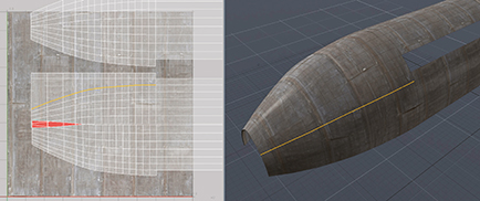
MODO UVS
Modo has a number of UV projections to use. I tend to use their simpler projections and use the atlas projection for my needs. Here individual poly edges were selected and straightened out to eliminate distortion of the image map.
STEP 12
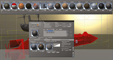
APPLYING MATERIALS IN VUE
With individual items tagged with colour, it’s easy to select an item and apply a procedural material in Vue. A material was created using two different metals with the ability to alter the proportions of each. For a Civil War sub that would have been made of basically a few different metals at best, Vue’s ability to create a unique material and then create variations of it worked extremely well.
STEP 13
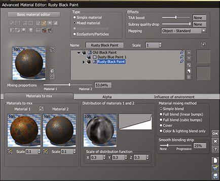
MATERIAL CREATION
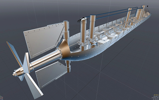
Selecting just one of the two materials from the blend above, two different materials were blended together to further alter the look and create a custom metal, which was then saved as a procedural material for future use in other projects. This material optimization includes the ability to adjust the bump and, where two materials are used, distribution based on orientation so that Material 1 appears at the lower heights of an object. A cylinder can be chrome at top and slowly blend into rust towards the bottom.
STEP 14
CREATING OCEAN STORM WAVES
I often see people trying to create seas with a single mesh, but for a storm state, a close POV and two large objects, and to have the most options for control, I elected to create a little over half a dozen terrains which could then be resized, rotated and stretched. As the images show, it would be very difficult to create such a stormy sea with a single mesh.
STEP 15
BEHIND CAMERA
A non-perspective view from behind the camera shows how dramatically the terrains needed to be raised to achieve the effects wanted. Creating this type of orientation with a single mesh would have required a lot of work and remodelling.

STEP 16
RIGHT SIDE OF CAMERA
This right side view shows how the terrains were actually lilted for effect so that they are leaning at a steep angle.

STEP 17
TOP VIEW
This top view shows just how widely spread the larger terrains were and how overlapping the smaller terrains were near the submarine to provide the wave action desired. Again, doing this with one mesh would have required going back into Modo to create a specific terrain through modelling, and then being restricted when placing the objects back on it in Vue.
STEP 18
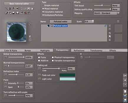
CHANGING TERRAINS TO WATER
Vue provides a number of water procedurals which, like metal and all their other materials, allows for unlimited customisation. Here I kept it simple and used a default polluted water preset. As the image was rendered in Vue it was possible to adjust these material presets with ease if necessary.
STEP 19
THE TOWING SHIP
The Alligator was being towed to an upcoming engagement when it was lost during the storm off Cape Hatteras. I needed a steam ship of the period to represent the actual one. Since it was going to be visually lost and merely a shadow in the storm, I used a purchased asset, the Patrick Henry, and removed the paddle wheels in Modo.
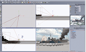
STEP 20
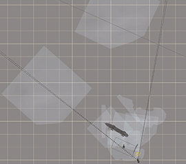
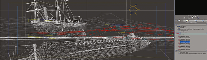
PLACING ELEMENTS IN A TROUBLED SEA
With a high poly count, I switched to wireframe and began placing both vessels in the arrangement of terrains. This stage amounts to a trial and error approach of moving all the elements around as camera angles and perspectives were changed. Coming to a final point of view, the terrains were adjusted to create swells and spillovers for a truly stormy sea.
STEP 21
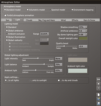
CREATING AN ATMOSPHERE
For what would be a dark, stormy scene, a simple atmosphere preset was selected and the sun was moved to the lower right. The main colour, as well as the ambient light colour, were all low key and dull in nature to add to the storm effect.
STEP 22
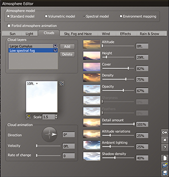
CLOUDED, FOG COVERED SKY
Low spectral fog and large cumulus clouds darken the scene and cover most of the visible sky leaving just a peek of the sun for possible light rays. A dramatic, if not particularly realistic, effect.
STEP 23
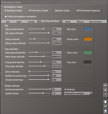
FOGGY BOTTOM
While the two vessels were not that far apart, fog was an important part of both darkening the scene and fading away the distance to isolate the viewer with the foreground event.
STEP 24
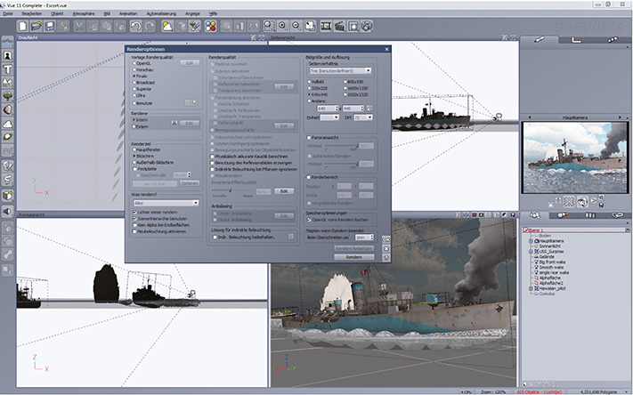
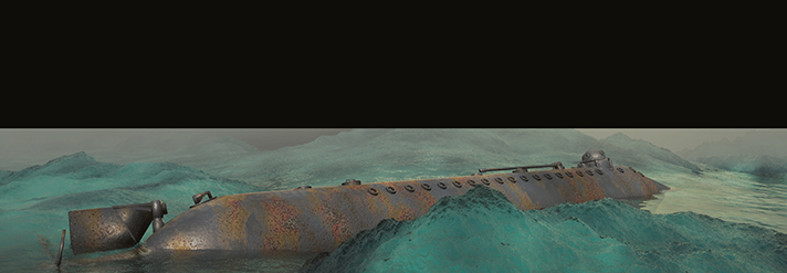
TEST SPOT RENDER
It’s worth doing a lot of test renders, trying out different POVs and lighting situations as well as different atmospheres. Here I was concerned with the placement of the terrains, their water procedural look, and coverage of the sub itself by a wave.
STEP 25
ADJUSTMENTS AND INITIAL RENDERS
Doing a number of draft renders and then final renders after a series of small adjustments in fog, lighting and water procedurals, a final image started to take shape. Once a final scene was reached, the desired size and pixel count were set. In this case it was for a final image measuring 40 × 14 inches at 300 dpi.
STEP 26
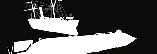
MASKING DEPTH
With the high resolution render finished both a tiff of the render as well as an alpha of the scene were saved so the sky and vessels could be isolated against the sea, making the post production work easier. In some scenes it’s also worth saving a Z-depth mask to use in Photoshop for depth-of-field adjustments.

STEP 27
ISOLATING THE SKY
By having the sky isolated it was easy to make adjustments to it as well as being able to composite other possible 2D textures and even sky effects.
STEP 28
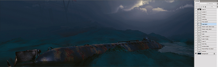
POST WORK IN PHOTOSHOP
With the render and masks in place in Photoshop, colour and contrast adjustments were made, adding in sun rays and sea spray to each layer. This was a time consuming but exciting time as it brought the image to life. With so many layers, there were a huge number of possibilities in what could be achieved. In this case I wanted to create a strong feeling of motion with the sea spray. Each spray was done with photo brushes, rotated and resized to match the effect required in a particular area.
STEP 29
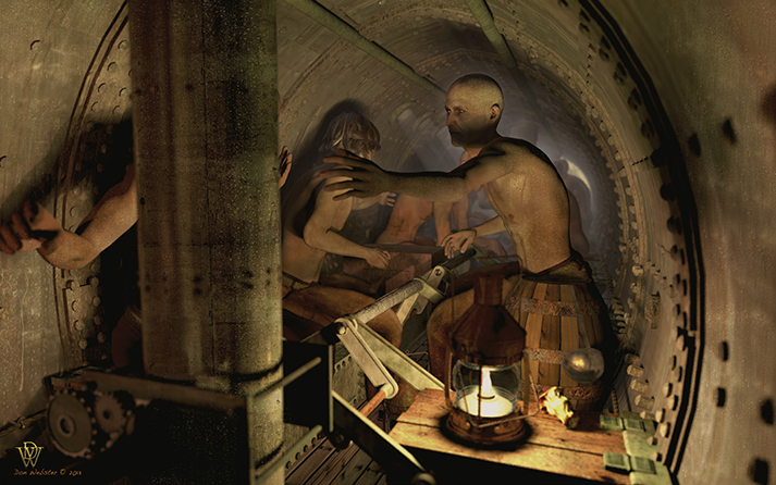
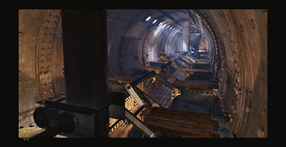
ALTERNATIVE INTERIOR SCENE
Sometime after finishing the exterior scene, I went back and started working on an interior scene; that dark, damp, lateen lit cave of a working machine. This shows much of the working and how narrow the space was.
STEP 30
ADDING A CREW
The project was then finally finished by adding a crew and producing another alternative render. As you can see there was very little room to move around and actually no room to stand upright.