
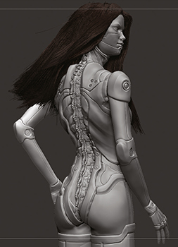
SCULPTING A GLAMOROUS ANDROID
James Suret explains how he created a sexy robot character using ZBrush and Photoshop
IDEAS IN DEVELOPMENT
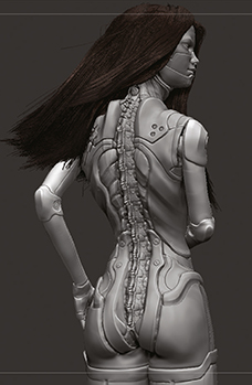
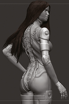
The aim of this project was to create a glamorous female android character. The character would be posed facing away from the camera, similar to shots seen in fashion and style magazines. This meant the back of the character needed to have some interesting features. The spine would be one of the main features of the character and I initially wanted to add some robotic wings. I wanted to create and style the hair using the Fibermesh feature and groom brushes in ZBrush. Previously, I had only used small amounts of Fibermesh so I was looking forward to creating a long hair style and learning from the experience. This project was also a good challenge because I had been focusing on creating 3D creatures recently and I needed to add some diversity to my portfolio.
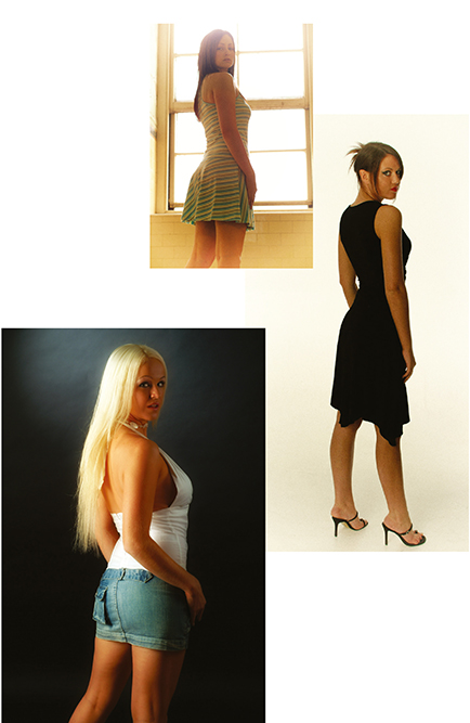
The type of fashion model pose that the android character was going to emulate, but a little sexier.
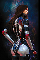
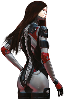
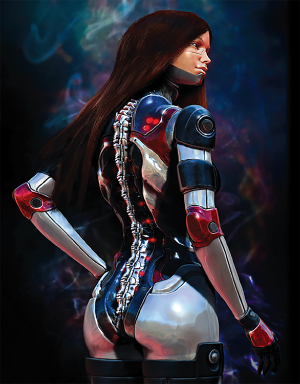
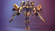
Nova-25 – final image.
| PROJECT | NOVA-25 |
| SOFTWARE USED | ZBRUSH, PHOTOSHOP |
| RENDERING TIME | APPROX 1 HOUR |
| ARTIST | JAMES SURET |
| COUNTRY | UNITED KINGDOM |
STEP 1
PREPARING THE BASE MESH
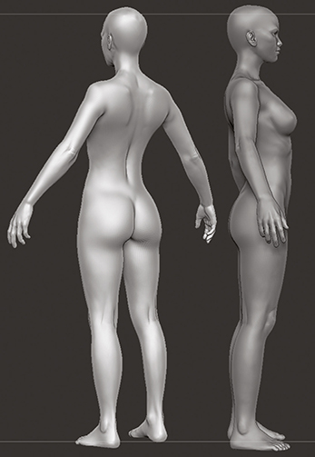
For this character I decided to start from a base mesh rather than using ZSpheres to speed the process up. It was good to have an accurate anatomical base to make the character believable. I downloaded this base mesh for free from www.zbrushcentral.com. The first thing I did was to enable symmetry and change the proportions in order to give her a slender and idealistic feminine look.
STEP 2
ROUGH BLOCK-IN OF FEATURES
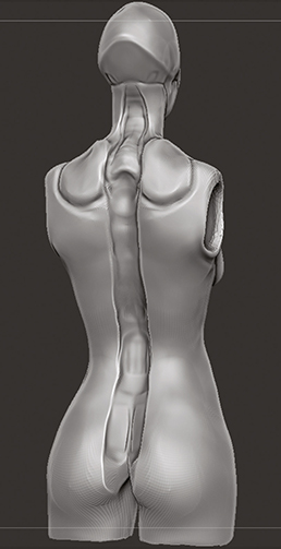
Now the base was ready I had to decide on the main features of the character. At this point I wasn’t entirely sure what the armour or skin would be made of or how it could be separated up into panels and materials. Using the Clay and Claytubes brushes I scooped out cavities for the robotic spine and neck and then started to build up the shoulder panels.
STEP 3
FURTHER BLOCKING-IN OF SHAPES
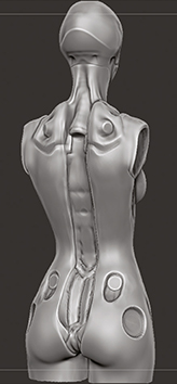
I started to section up parts of the suit using the Damien Standard (DS) brush and polished the surfaces with the Flatten and Smooth brushes. Also, I cut out some holes using the Clay brush that could potentially be used for detailing. From the start I knew the character would be facing away from the camera so I saved some time by barely detailing the front of the body.
STEP 4
ADDING SEPARATION BETWEEN FORMS
Next, parts of the body were cut up into areas using the DS and Claytubes brushes. The metal frame section was defined at the bottom and the shapes down the cavity where the spine would go. Then the metallic area was slightly polished with the Smooth brush to give a hint of the material it could be made from.
STEP 5
ADDING INITIAL DETAILS
After using Dynamesh the mesh was now at about one million points. This enabled me to add finer detail and edges to the central area of the back. The Pinch brush was used to create sharper edges and then the Flatten and Hpolish brushes to tidy them up.
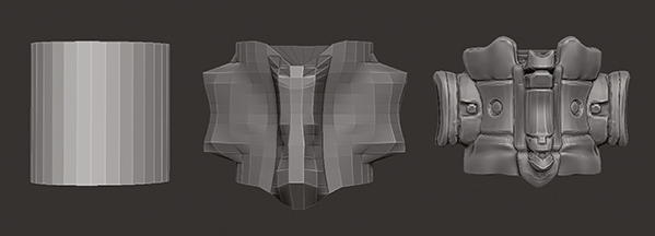
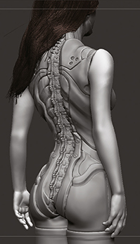
STEP 6
CREATING THE SPINE
I decided to create the robotic spine using an InsertMesh and the curves feature. Starting with a basic cylinder for the vertebra, using the move brush the main shapes were pulled out. Then mainly using the DS brush, the form was sculpted to resemble a human vertebra whilst adding some embellishments.
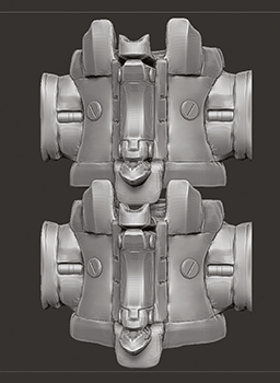
STEP 7
DETAILING THE SPINE VERTEBRAE
Now that I had the basic shape of the vertebra, I defined more details using the DS brush and polished with the Flatten and Hpolish brushes. Some InsertMesh shapes were added that could be used as lights and polygroups were added to section the materials up. Finally, using some InsertMeshes of screws some mechanical details were added to the piece.
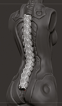
STEP 8
INSERTING THE SPINE
When the vertebra was completed it was turned into an InsertMesh and Curve mode was enabled. Then the rough shape and length of the spine over the back of the character were drawn out. Next, I turned the snap option off for Curve mode so that I could tweak the position of the spine in order to make it look like it fitted properly into the spine cavity.
TOP TIP – SCULPTING MATERIALS
It sometimes helps to modify the basic materials in order to see details better whilst sculpting. Click on materials and increase the cavity detection. You can also decrease intensity B slightly to increase the shading and define cavities.
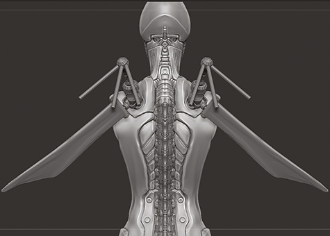
STEP 9
EXPERIMENTING WITH THE WINGS
I initially wanted to add robotic wings to this character so I started kit bashing by adding InsertMesh shapes to create a form that I could then sculpt on top of. However, as I had already decided on the angle of the camera and the size of the final render I realised that the wings would obscure too much of the character so I removed them.
TOP TIP – ALTERNATE SMOOTHING
If you’re trying to smooth an area of the mesh out but not getting the results you want, try letting go of the Shift key whilst still holding down the mouse button and it will use an alternative smoothing method.
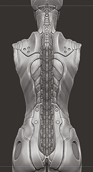
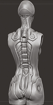
STEP 10
ADDING FURTHER DETAIL AND SEPARATION
Now that the spine was in place, the top and bottom of the body was modified to better accommodate it. Then using the DS brush separation lines on the shoulder and waist were created. Next, using the Clay brush some smooth cavities along the upper body were carved out to resemble ribs.
STEP 11
EXPERIMENTING WITH INSERTMESHES
At this stage I experimented further with InsertMesh shapes to build up some interesting additions to the neck and shoulders. However, I decided the model didn’t need the extra details in that area and it was better to keep it sleek and simple.
STEP 12
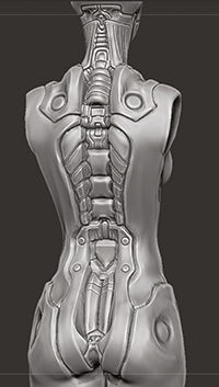
DETAILING THE NECK AND HEAD
The polygon count of the mesh was increased to about 4 million points. This meant I could then start adding fine detail to the back of the neck and head.
STEP 13
ADDING DETAILS WITH INSERTMESHES
Now that I had sculpted the fine details I started inserting more screws and wires to give the character a robotic look. A tube was added to the back of the neck but I wasn’t sure if this would be hidden by the hair. However, it’s good to put as much detail and as many features in as possible just in case you want to show them later.
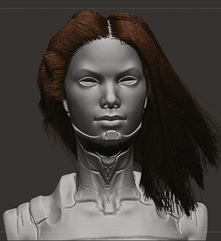
STEP 14
ADDING THE HEAD
To add the head the original base mesh was re-opened and the face cut out using the Lasso selection tool. The hidden geometry was deleted then the face was inserted into the project as a subtool and the Transpose tool was used to fit it inside the neck of the suit.

STEP 15
CREATING MASKS FOR THE HAIR
When creating long hairstyles using Fibermesh in ZBrush it is very important to create Polygroups so that you can control the shape of the hair. Symmetry was turned off then a section of the scalp was masked out and turned into a Polygroup. Then this process was repeated for the rest of the scalp.
TOP TIP – CREATING HAIRSTYLES
When creating long hairstyles I recommend creating Polygroups of the scalp before generating the Fibermesh, then set Auto Masking to “Mask By Polygroups” 100 per cent. Now you can brush and move segments of the hair one at a time to create complex hairstyles.
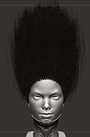
STEP 16
GENERATING THE HAIR
Next, the Fibermesh was created using one of the default templates (Fibers 142) with gravity set to -1 so that it was easy to see the length of the hair. The coverage was set to 30 per cent, the Max Fibers to 18 and the Length to 1000. This then created a separate subtool for the generated hair which included the Polygroups previously created.
STEP 17
STYLING THE HAIR
The brush option Mask By Polygroup was set to 100. This meant I could brush sections of the hair using the Polygroups I had already created without interfering with the rest of the hair. Using the GroomHairBall brush, I pulled down one section at a time and then using the GroomHairLong brush the windswept look of the hair was created.
STEP 18
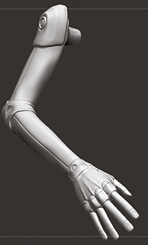
ADDING THE ARMS
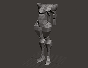
At this point the hair was taking shape and I was pleased with how the body looked. The original base mesh was opened again and the arms were sectioned off using the Lasso selection tool and then inserted into the project as a subtool. The arms were smoothed out slightly to look more like armour rather than skin and then shaping of the shoulders started.
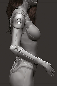
STEP 19
ADDING DETAIL TO THE ARMS
The arms needed detailing to match the style of the body. To do this the Claytubes and Flatten brushes were used to pull out some basic shapes around the shoulders and elbows for padding and armour. At this point I wasn’t sure whether to leave the hands looking completely human or robotic.
TOP TIP – SOFT MASKING
When posing organic characters you usually need to create smooth bends, for example, the elbow or knee. Rather than masking the area and clicking on it several times to soften the mask you can hold down the Ctrl key and lower the RGB opacity.
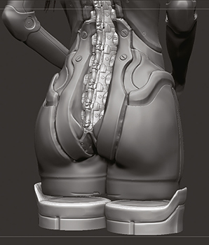
STEP 20
ADDING THE STOCKINGS
I hadn’t worked on the legs yet so I decided to add some sexiness to the character by creating futuristic armoured stockings. A basic cylinder shape was inserted, the mesh was divided and using the Claytubes and Flatten brushes the tops of the stockings were created and the seam was cut out with the DS brush.
STEP 21
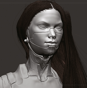
DETAILING THE FACE
The character now looked like a good mix of human and android so I decided to only add small changes to the face. A separation line was created with the DS brush and the Pinch brush used to tighten it up. Then the face was smoothed out to make it look slightly fake rather than actual flesh.
STEP 22
CREATING THE HANDS
To create the hands the fingers were cut off and the hand details were sculpted. Then a finger was sculpted from a basic cylinder. The finger was duplicated four times and then they were all moved into place on the hand before being resized slightly.
STEP 23
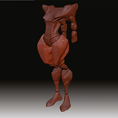
INITIAL POSE
Next, using Soft masking and the Transpose tool the arms were moved into place. In the initial pose I was going to show the character with her arms wrapped around her body and looking away to the side.
STEP 24
CHANGING THE POSE
I reconsidered the pose after doing a test render, I felt it was rather weak and made the character look too fragile. The character was repositioned so that it was more dynamic and the pose suggested movement.
STEP 25
REFINING DETAILS
Now with everything in place I looked over the entire character and added more details to the hands, shoulders and stocking tops. Additionally, the hair was brushed further to tidy it up and also pulled down over the character to create the illusion of gravity.

STEP 26
ADDING MATERIALS
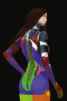
With the sculpting and pose completed parts of the body were masked out and some materials were added to those areas to section up the armour. To the white outer areas of the body a matte material was added and to the rest of the sections black and red metallic materials were added. A skin material was also added to the face.
STEP 27
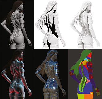
CREATING THE RENDERS
A basic render was created without shadows to use as the base layer in Photoshop. Then the light placement was moved to create shading across the back and this was rendered. The individual parts of the armour were selected, filled with different flat coloured material and rendered to use as a mask. Also, several renders were created using different materials so that I had options when compositing.
STEP 28
LAYERS AND COMPOSITING IN PHOTOSHOP
Next, the renders were opened in Photoshop. I started with the basic render then added the shadow and ambient occlusion layers, inserting the silhouette mask and material masks layers on top. Some of the extra material renders were experimented with, changing the layer modes until I was happy with the lighting and colours.
TOP TIP – SCULPTING STRAIGHT LINES
It’s often necessary to cut out straight lines in the mesh, for example, seams on clothing or panels on metal. To achieve this you can hold down the mouse and then hold down the Shift key and drag the mouse, the mouse cursor will then snap to a straight line.
STEP 29
CREATING THE BACKGROUND
The abstract background was then painted using a few custom brushes and blurring the image to create a colourful smoky backdrop. Using a large soft brush the shadow and light were painted to help focus the eye on the centre of the image. Finally, a layer of noise was added to emulate the way light scatters into the distance.
STEP 30
ADDING TEXTURE AND EFFECTS
To add realism a scratched metal texture was added and using the mask the excess texture was deleted. This process was then repeated with skin texture for the face and painting on the eyes and eyebrows. Finally, the red glows were painted on a new layer using a soft round brush set to Multiply. Also, the specular shine was added coming from the edges of the metal.
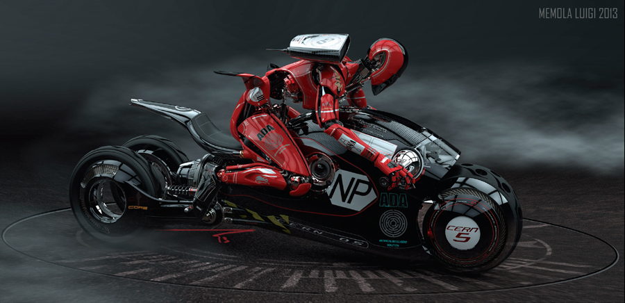
![]() The project concerned a robot avatar, who is a motorcycle rider on a larger vehicle. The vehicles of the AEG27 (Advance Engine Gear) range are from a not too distant future. The pilots will control the remote robot avatar and the teams will fight for the championship title of CERN O5. Being a designer I thought a lot about the aesthetics and functionality of every component. The front wheel has holes that allow air to enter the turbine, the rear wheels are free of the hub. The design of the robot is minimalist with the frame and the engine being the high technology elements, but the plates are just aesthetic to mimic the muscles of a person. AEG27 other vehicles are visible in my personal portfolio on Behance.
The project concerned a robot avatar, who is a motorcycle rider on a larger vehicle. The vehicles of the AEG27 (Advance Engine Gear) range are from a not too distant future. The pilots will control the remote robot avatar and the teams will fight for the championship title of CERN O5. Being a designer I thought a lot about the aesthetics and functionality of every component. The front wheel has holes that allow air to enter the turbine, the rear wheels are free of the hub. The design of the robot is minimalist with the frame and the engine being the high technology elements, but the plates are just aesthetic to mimic the muscles of a person. AEG27 other vehicles are visible in my personal portfolio on Behance.![]()
| PROJECT | ROBOT AVATAR CERN 05 |
| SOFTWARE USED | RHINOCEROS 4, KEYSHOT 4, ADOBE PHOTOSHOP CS3 |
| RENDERING TIME | 7 HOURS OUT OF TOTAL OF 110 HOURS |
| ARTIST | LUIGI MEMOLA |
| COUNTRY | ITALY |
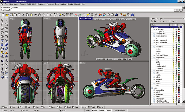
All the various layers of the completed model from within the Rhinoceros interface.
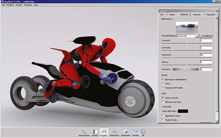
The model imported into KeyShot for rendering. An HDRI lighting system is being applied.
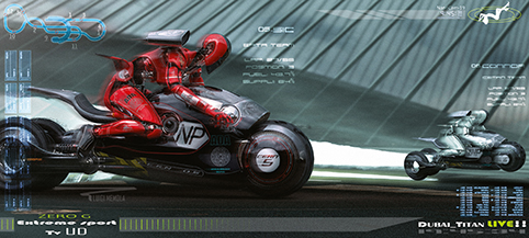
The actual race for the robot avatar in progress where a human controls the machine.
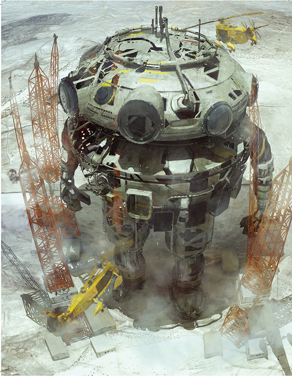
![]() The image was made as part of a series of pieces depicting derelict or broken machines/ ships in sci-fi environments. The 3D model was from an older project that I decided to re-use for this. It was modelled and rendered in Lightwave 3D then painted over in Photoshop to complete the image with more of an artistic look rather than a clean render.
The image was made as part of a series of pieces depicting derelict or broken machines/ ships in sci-fi environments. The 3D model was from an older project that I decided to re-use for this. It was modelled and rendered in Lightwave 3D then painted over in Photoshop to complete the image with more of an artistic look rather than a clean render.![]()
| PROJECT | REBUILD |
| SOFTWARE USED | LIGHTWAVE 3D PHOTOSHOP |
| RENDERING TIME | N/A |
| ARTIST | NEIL MACCORMACK |
| COUNTRY | SWITZERLAND |
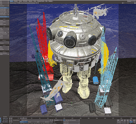
Creating the supporting elements of cranes and helicopters that are working on the giant robot vehicle.
![]() This was a personal project where I created a series of military-grade robots. This one is an assault robot, hence it has two large weapons on the ends of its arms. The lighting of the eyes was to give it that contemporary shining/futuristic lighting look that you get in movies.
This was a personal project where I created a series of military-grade robots. This one is an assault robot, hence it has two large weapons on the ends of its arms. The lighting of the eyes was to give it that contemporary shining/futuristic lighting look that you get in movies.![]()
| PROJECT | CAPTAIN-TE |
| SOFTWARE USED | ZBRUSH, MODO, KEYSHOT |
| RENDERING TIME | APPROXIMATELY 120 MINS |
| ARTIST | RAFAEL AMARANTE |
| COUNTRY | BRASIL |
The robot was modelled in Modo as it is one of the better 3D packages for hard surface modelling.
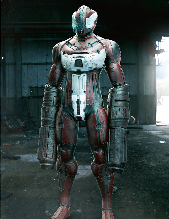
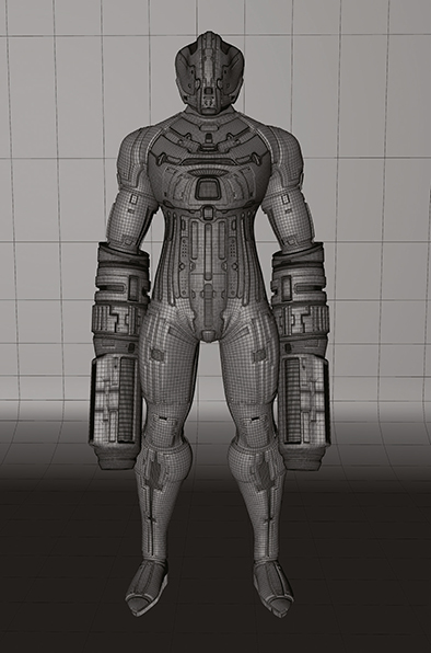
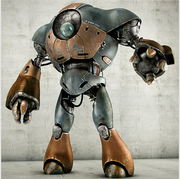
![]() I was taking part in a hard-surface modelling workshop with Pedro Toledo and needed a model to use. I had always loved this robot design, originally sketched by my friend, Thiago Almeida.
I was taking part in a hard-surface modelling workshop with Pedro Toledo and needed a model to use. I had always loved this robot design, originally sketched by my friend, Thiago Almeida.![]()
| PROJECT | ROBOT |
| SOFTWARE USED | 3DS MAX 2012, ZBRUSH, MUDBOX, TOPOGUN, UVLAYOUT AND V-RAY |
| RENDERING TIME | 2 HOURS |
| ARTIST | VICTOR HUGO DIAS DE SOUSA |
| COUNTRY | BRASIL |
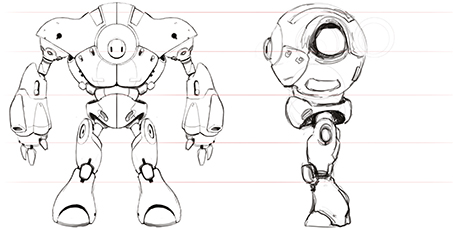
This is the original drawing by Thiago Almedia of the StopBot which formed the basis of the project.
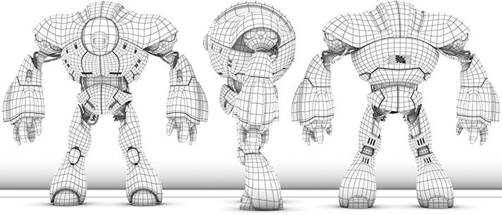
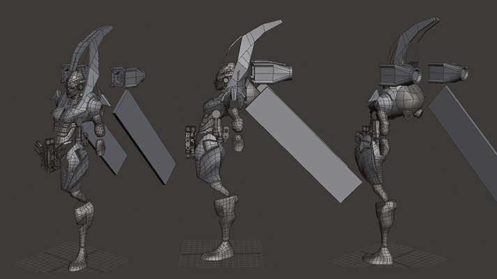
Wireframe of the completed model as seen from the front, side and back.
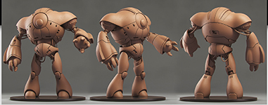
The robot on a turntable to showcase the model. This is a clay render without any textures.
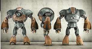
Same turntable view of each side of the bot, but now with the textures in place.
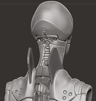
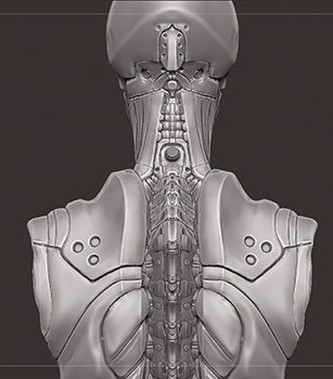
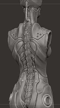
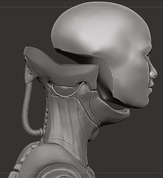
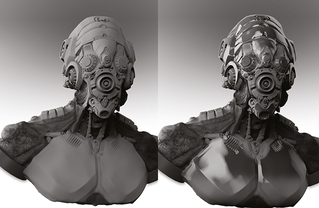
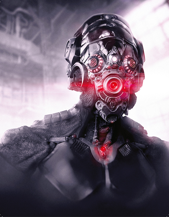
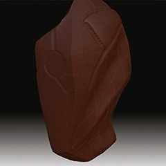
![]() The aim for this project was to create a robotic alien character and render it in a realistic way. I initially sculpted this as a complete character with a feminine look but later decided to focus on making a more detailed bust rather than whole character. To do this I replaced the chest/neck and also made it more masculine. I wanted to make use of the ZBrush insert mesh feature as I hadn’t used it much before this. I added lots of screws and panels from the insert mesh library that came with ZBrush which adds to the realism of the character.
The aim for this project was to create a robotic alien character and render it in a realistic way. I initially sculpted this as a complete character with a feminine look but later decided to focus on making a more detailed bust rather than whole character. To do this I replaced the chest/neck and also made it more masculine. I wanted to make use of the ZBrush insert mesh feature as I hadn’t used it much before this. I added lots of screws and panels from the insert mesh library that came with ZBrush which adds to the realism of the character.![]()
| PROJECT | ALIEN CYBORG |
| SOFTWARE USED | ZBRUSH, PHOTOSHOP |
| RENDERING TIME | APPROXIMATELY 35 HOURS INCLUDING SCULPTING |
| ARTIST | JAMES SURET |
| COUNTRY | UNITED KINGDOM |
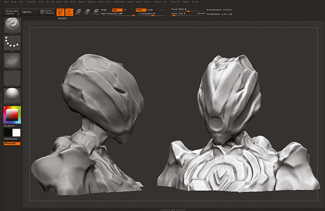
Sculpting the basic shapes of the character using the Move and Clay brushes. Also creating some separation between panels/sections of the armour.
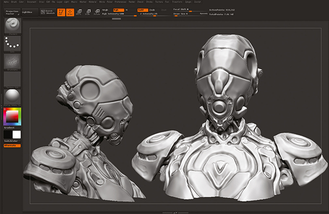
Having increased the density of the mesh I then added more detail whilst leaving some parts bare in order to add insert mesh objects later.
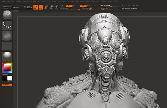
Further refinement of the features of the bust – I polished some of the surfaces as well as added insert mesh objects such as screws and vents.
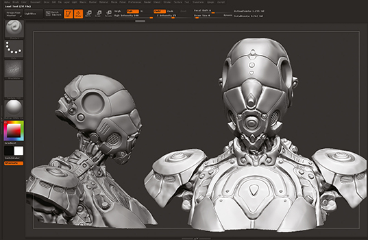
I re-created the chest/ neck to look more alien and masculine. I also added more insert mesh objects and polished the metal surfaces using the Flatten and Polish brushes.
Several layers were rendered out including ambient occlusion, shadow, reflection and specular lighting. In Photoshop I then painted skin and metal textures on top.
MIXING NATURE AND ROBOTICS
Christopher Parnian explains how he fused two styles together to create a robot with organic stylings
MECHANICAL DESIGN DEAS
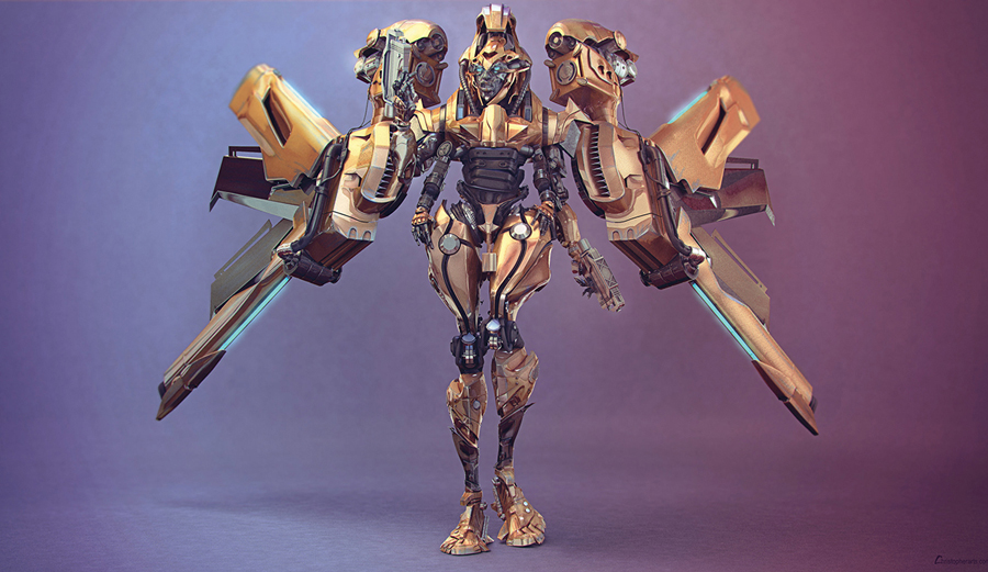
I created this robot character for a challenge where the guideline was creating a robot or a vehicle by taking inspiration from a creature or nature. I chose a Queen Bee as the inspiration for my character. When creating something we usually look at the physical appearance or the distinct characteristics to get some idea of what to use in the CG design, but in this case I considered more its personality and instinctive behaviours. These included concepts such as being hard working, defending of the hive and protecting itself against enemies by stinging. I often search the Internet for photos of things like machines, mechanical industry, animals, and insects. I also check out artworks of other artists to see what kind of inferences and references they are using. For the robotic Queen Bee, the whole purpose was to bring the somewhat tedious nature of mechanical industry objects to life. This meant creating a robot with a combination of mechanical elements and beautiful fashion models.
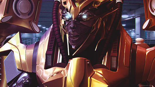
A close-up shot of the head of the final rendered image.
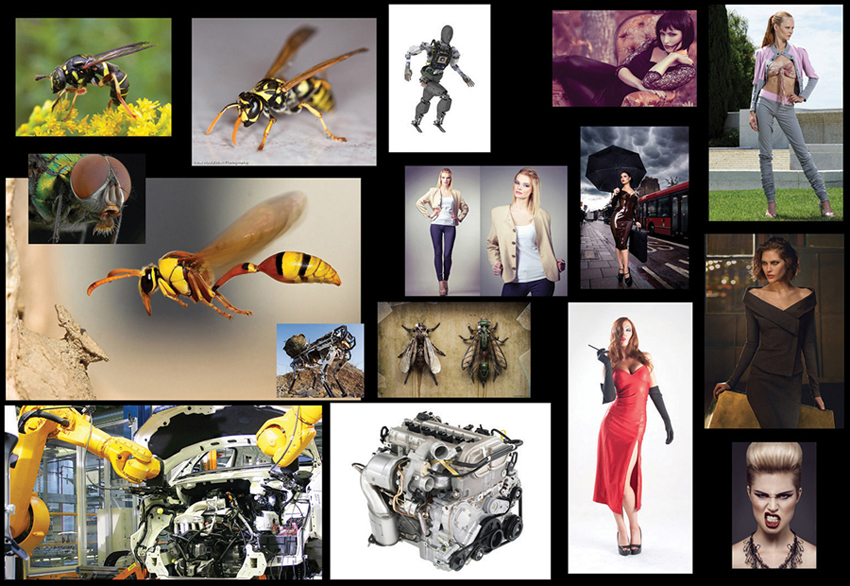
These are a bunch of images that I have collected for inspiration, from fashion models to machinery and bees.
Queen Bee – final image
| PROJECT | QUEEN BEE |
| SOFTWARE USED | 3DS MAX, ZBRUSH, XSI SOFTIMAGE, MENTAL RAY, PHOTOSHOP |
| RENDERING TIME | 6 WEEKS TOTAL |
| ARTIST | CHRISTOPHER PARNIAN |
| COUNTRY | IRAN |
The process started by modelling a generic body or blockout, in 3ds Max. I didn't draw any preliminary sketches because I wanted to jump into the design right away with the sculpting stage. The base mesh of the body was built using a poly-by-poly modelling technique. This means that the mesh was built by basically extruding edges from existing polygons, after which the new points are moved to form the required shape and so on. The overall shape and surface were kept pretty clean so they could be pushed drastically in ZBrush later.
The base mesh had more than enough detail to get started so it was then imported into ZBrush and the Move brush was used to change the proportions and develop some interesting shapes. At this point I didn't care too much about stretched geometry. Once I got some interesting shapes I imported the mesh back into 3ds Max and added more edge loops in areas that had become too stretched. The basic premise behind a clean sculpt is to keep your polygons in as many quads as possible. Figure 1 shows the earliest low-poly concept model, which gives you an idea about the overall shapes that were sculpted using the Move, Standard and Inflate brushes.
The mesh was divided four to five times, just to make sure that there was enough geometry for the small, crisp details. At this point I started to concern myself with the surface. Piece by piece the shapes were carefully formed, starting with large areas and going down to the small ones. At the same time I kept looking at different kinds of reference images, just to keep myself inspired. I wanted to keep the overall profile simple and easy to read, but add a unique sci-fi aspect to the details.
Switching from Zadd to Zsub mode makes the alpha affect the surface in the opposite way. I especially like combining this approach with the new brush features in the latest version of ZBrush. It's so much fun to just experiment and explore different ideas. Sometimes I saved different versions and then worked on the one with the best design after the sculpting base mesh was completed. Resurface modelling methods were used to build the low poly model that could be imported into XSI SoftImage for more detailing.
Basic block outline from 3ds Max that was imported into ZBrush.
The early low-poly model which was being shaped and sculpted.
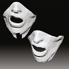
Trying different expressions to see which would work best for the overall effect.
The Standard, Inflate and Move brushes were used to add details to the mesh.
Assembling various components to go with the main body of the model.
TOP TIP – KEEP IT QUAD
The basic premise behind a clean sculpt is to keep your polygons in as many quads as possible. This avoids the model becoming stretched and too low resolution in places.
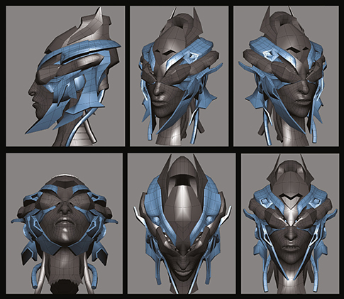
Rotating through the various views of the head to show the structure.
At this stage, the work in progress shows that almost all of the details have been completed.
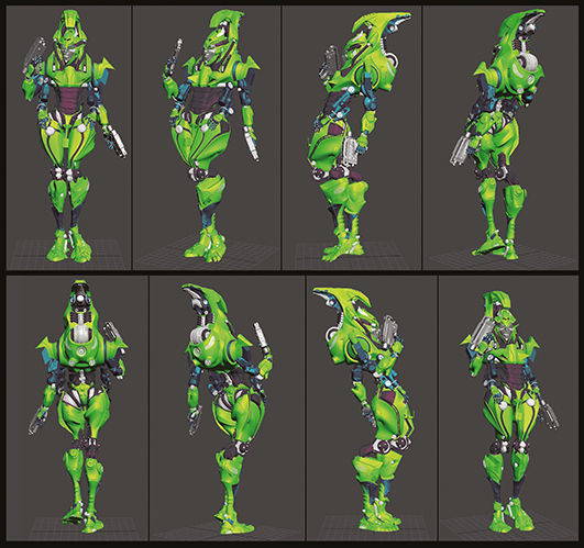
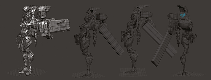
The final model on a turntable where all the details and features have been created.

The wings and aerial propulsion system for the model is shown from various angles.
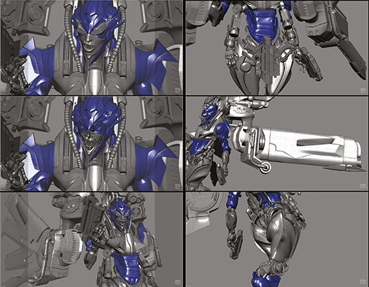
Close up shots showing hands, mouth, weapons, and the hydraulic system for the legs.
The Mental Ray Arch and Design material system was used for this project, as they are very good at portraying metal materials. The Arch and Design materials have some good preset settings with which to create all sorts of realistic materials and are an excellent starting point from which to create your own custom set-ups. An HDR image in the reflection map slot was also used, which helped greatly in achieving realistic metals instead of relying only on the environment reflections. The Arch and Design materials dramatically increased the render times, but the end results are usually much more natural so it's worth putting up with.
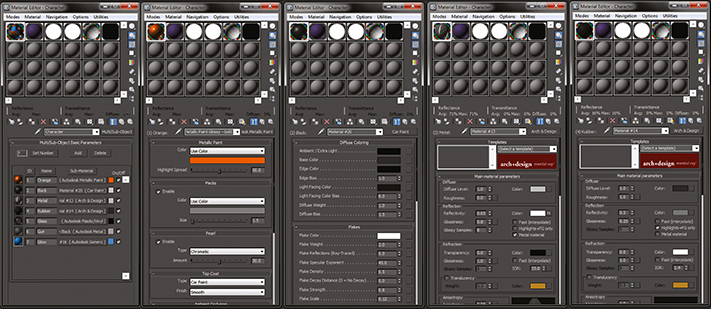
Material assignment in Mental Ray. The Arch and Design group is invaluable for creating realistic materials.
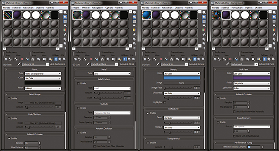
More materials including those for the glass elements and the metal of the hand guns.
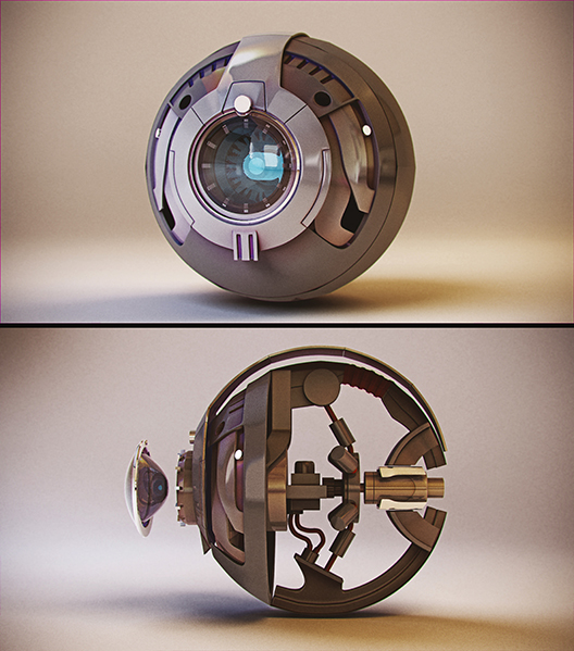
The eyeball system with glass and metal materials assigned for a realistic render.

One of the electromagnetic hand guns used by the Queen Bee figure.
The trick with lighting is to keep it simple whenever possible. With this in mind, only three groups of lights were used and each one has two lights for the whole scene. Also I used mr Sky Portal lights as this produced the smooth shadows I wanted. Figure 2 shows the entire lighting rig, consisting of six lights in three groups. The groups consisted of one key light as the main light source and two fill lights to add reflections and reduce shadow areas.
After some render tests it became apparent that there was a problem with the far left of the image being too dark. To resolve this the locations of the lights were changed and further test renders were produced until it came up with a satisfactory result. Producing a clay render of the figure allowed me to check for any modelling or lighting issues without being distracted by textures or materials.
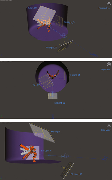
The lighting group setup from a variety of angles showing the use of key and fill lights.
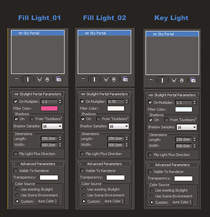
The settings for the three sets of lights shows the slight colour being used as the main light filter.
TOP TIP – HDRI LIGHTING
Using an HDRI image in the reflection map slot helped greatly in achieving realistic metals instead of relying only on the environment reflections.
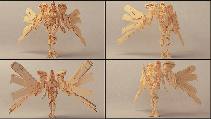
This is a clay render, just showing the lighting, so any problems with the model could be seen.
As some of the materials were quite heavy and took a long time to render, the render tests were set to a very low quality. This is always good practice and will speed up the workflow because the last thing you want to be doing is waiting around for test renders when making small adjustments. The default Draft settings were used for the tests and the image resolution was kept small to help keep it rendering quickly.
Once happy with the render and when the lighting looked reasonable, I moved on to a larger render. This render had slightly increased settings such as Bounce and Final Gather rays cast to improve the quality. The important things were to limit the depth of reflections for the ray tracer.
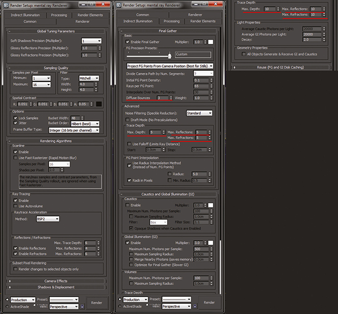
The render setup, with ray tracing limits highlighted, for using the Mental Ray rendering engine.
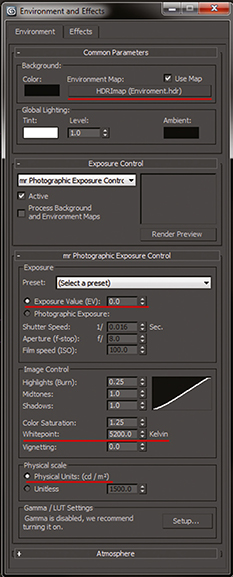
An HDRI map was used to create a more rounded lighting solution while the colour temperature was set to 5200K.
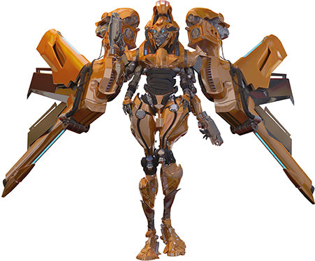
A test render against a white background to check for reflections and a clean finish.
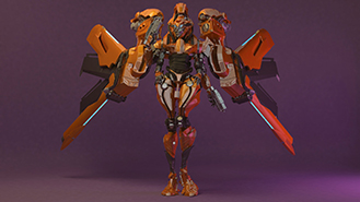
A final test render with the colour background, before increasing the quality for the final render.
TOP TIP – TEST RENDERS
When using detailed and high resolution textures, even preview renders can take a long time to churn out. Reduce this time by lowering the resolution to the smallest size at which you can still see the details and set the quality settings in the render engine as low as possible.
QUEEN BEE BY CHRISTOPHER PARBIAN
![]() 3DS MAX, ZBRUSH, XSI SOFTIMA, MENTAL RAY, PHOTOSHOP
3DS MAX, ZBRUSH, XSI SOFTIMA, MENTAL RAY, PHOTOSHOP
![]() 6 HOURS
6 HOURS