
Creating and Using Alpha Maps/Channels
In this chapter, we are going to look at the most common methods of creating various forms of vegetation used in the games industry.
As creating foliage and leaves still relies heavily on alpha maps or a texture with an alpha channel, I’ll start off with a brief explanation.
An alpha map is a black-and-white or grayscale image, which controls the transparency of a surface when it’s applied to a mesh using a shader. In the example pictured in Fig. 4.1, the alpha map is on the left, the diffuse texture is in the middle, and the final result applied to the mesh is on the right.
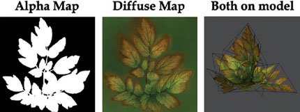
FIG 4.1
This works because the shader is interpreting values of 100% white as being fully opaque, and values of 100% black as being fully transparent. Any gray tones between 100% black and 100% white will be transparent.
Now that we know what an alpha map is, let’s look at how we go about creating them.
The first step is always the source image for the diffuse. Whether it is hand painted or taken from a photo, you’ll need to have this first before you create the alpha map. I’ll use the previous example to demonstrate.
This was initially taken from a photo and then modified using a mixture of Photoshop’s blending modes hand painting.
Initially, I “extracted” the leaves I wanted from the original photo and then used them to create the alpha channel.
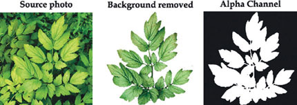
FIG 4.2
There are a few ways to do this.
I could simply create an alpha channel and start painting white around the leaves I want visible using the standard brush tool, but this takes time and also means the background will remain. I wanted to remove this.
I started by creating a 512 × 512 image file. I then copied the source image into this file and scaled it to fit into the square texture page (Ctrl + T). I then used the Lasso tool to create a selection around the area I wanted to keep.
I then inverted the selection by going to Select > Inverse on the menu bar. I then deleted the highlighted pixels. In a few key strokes, a large chunk of the unwanted image has been removed.
For the remaining pixels around the leaves, you could either use the eraser or manually paint the pixels out or you could use the magic wand tool to make pixel selections and delete them. The magic wand works best when the background is a different colour to the leaves, for example, a blue sky.
In this instance, it also works as there is a decent level of contrast in the image, but the tolerance needs to be kept low as the image is mainly green.
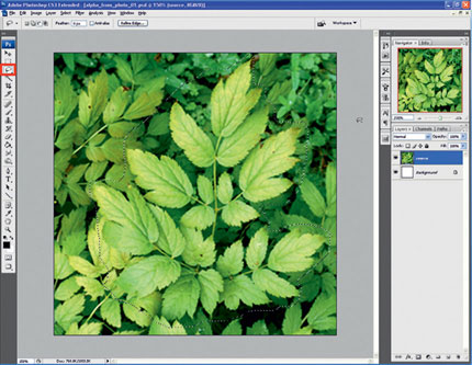
FIG 4.3
I decided to use the magic wand to quickly remove chunks of the image. I then finished up by using the eraser to manually tidy up the final few stray pixels.
I also adjusted the levels and hue and saturation on the final version before starting work on the diffuse texture.
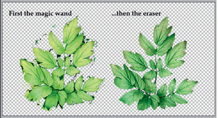
FIG 4.4
Now, we have separated out the piece of vegetation. We can quickly use this to create the alpha channel or at least a good starting point.
With the layer that the leaves are on selected, hold Ctrl + A and then select the small thumbnail image on the left of the layers name. This will select all pixels on the currently selected layer.
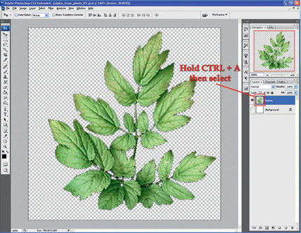
FIG 4.5
With this selection active, click on the channels tab. Go to the bottom right and click on the new layer icon highlighted in Fig. 4.6.
This will create a new alpha channel in the texture file. Next, select the standard brush tool at 100% opacity and paint the selected area. The result is fairly good, but there are a few gray and white pixels around that will need painting over with 100% black (RGB 0,0,0).
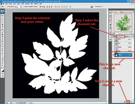
FIG 4.6
When the alpha channel has been cleaned up, we can preview the results in Photoshop over the RGB image.
Do this by turning on the RGB channels by clicking on the box to the left of the RGB channel at the top of the channels list. This will show or hide these channels. The same applies to the alpha channel.
When the alpha channel is displayed over the RGB channels, it will only show pixels under the white pixels of the alpha channel. In the next image, all the purple area represents the black values of the alpha channel.
You can change the color and opacity of the alpha channels appearance by double-clicking on the alpha channel.
It’s worth noting that you can still paint and edit the alpha channel while viewing all the channels at once.
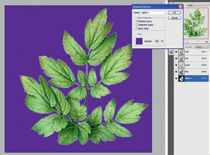
FIG 4.7
The last step would be to save out the final texture (once the diffuse map is complete) with the alpha channel, so it can be used in 3ds Max. There are two ways to get the alpha channel or map displaying in real time in the viewport.
The diffuse texture can be saved with the alpha channel in the same file with a format that stores the alpha information. Some formats are BMP, PNG, TIFF, TGA, and .DDS.
This texture, which will contain the diffuse and alpha channel, will need to be assigned to both the diffuse and opacity slot in a material. When it is assigned to the opacity slot, the bitmap parameters will need adjusting. By default, the Mono Channel Output is set to RGB Intensity. It needs to be changed to Alpha.
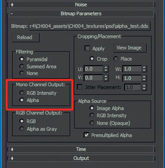
FIG 4.8
In the second method, I saved out the alpha channel as a separate texture. This can be done by pressing Ctrl + A over the selected alpha channel to highlight it, Ctrl + C to copy the selection, and then Ctrl + V in the RGB channels in the layers tab to paste it as a new layer. Then save the file as a separate texture after flattening the image.
Then just assign it to the opacity slot in the 3ds Max material and assign the diffuse texture into the diffuse slot.
Both methods should display the diffuse map working with the alpha map in the viewport once Show Standard Map in Viewport is turned on in the material and the following display mode selected main menu > Views > Show Materials in Viewport as > Standard Display with Maps is also on.
That concludes alpha maps—next we’ll take a look at diffuse maps.
Creating the Diffuse Textures for Vegetation
In this section, I’ll demonstrate how I created all the diffuse texture maps in Fig. 4.9.
The first thing to look at is the layout of the textures. The bushes in the first two images take up the entire texture sheet. This was intentional as I intend for the bushes to range from a medium to large size, so giving them more texture space will result in a higher resolution. All the textures are 512 × 512 pixels.
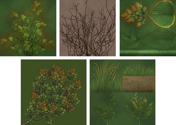
FIG 4.9
The texture sheet in the top right consists of four different types of leaves that will be used to create a variety of plants. This includes a horizontally tiling stalk section at the bottom, which will be shared between the various plants. Each leaf gets about 256 pixels square of texture space. These leaves are intended for small- to medium-sized plants.
The benefit of sharing many elements on a single texture sheet will mean that there are less individual texture files to deal with. In terms of real-time rendering in a game engine, the engine will also only have to call upon one texture and not four.
I also followed this concept of sharing through on smaller models on the bottom right image. This consists of a variety of grass and small plants, which will be used as a cheap solution to filling an environment full of vegetation.
The texture on the bottom left will be used as foliage for a tree. The leaves run diagonally across the texture sheet so that the space is used more efficiently.
If we were to have it vertical like the bushes, this would result in a top-heavy texture with a lot of wasted empty space at the bottom.
Let’s move on to the actual texture creation.
The texture layout is the only real difference between all of these textures. The technique for creating the diffuse texture is largely the same for all of them.
I’m going to take the leaves used in the alpha map section to demonstrate this technique.
In the previous section, we extracted the leaves from the photo similar to the Fig. 4.10.
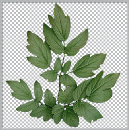
FIG 4.10
The first step is creating a background. Use the colour picker to select two different green colors, one for each swatch. Make sure there is enough contrast between the values, so we get a good result.
Then create a new layer (Shift + Ctrl + N). We’re going to use the clouds filter to create a random blotchy background. Go to the main menu > Filter > Render > Clouds.
You may need to try adjusting the two colours a few times to get a good result. You should now have an image similar to the one in Fig. 4.12.
The layer the leaves are on has the blend mode set to normal. You could easily play around with all the different modes to see the results. The one technique may not work every time. It all depends on the initial photo reference.

FIG 4.11
The issue I have with the leaves as they are now is that I don’t like the varying colours and lighting from the photograph. In this instance, the color dodge blend mode worked really well to reduce these issues.
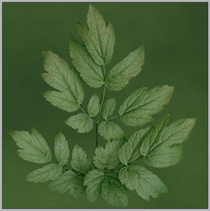
FIG 4.12
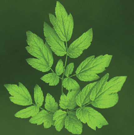
FIG 4.13
Obviously, now it is oversaturated, so use Image > Adjustments > Hue/Saturation to rectify this. Move the slider to the left to reduce the strength of the saturation. Even after this, I reduced the brightness and contrast on this layer to reduce the details further. The results are shown in Fig. 4.14.
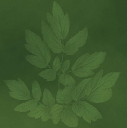
FIG 4.14
Now, copy the leaves layer (Ctrl + J). Then set the blend mode to normal. Press Shift + Ctrl + U to desaturate the image. Then press Shift + Ctrl + L to apply auto levels. This will increase the contrast of the values in the layer as in Fig. 4.15.
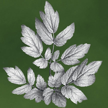
FIG 4.15
Set this layers blend mode to overlay. I also reduced the opacity to 46%. This will create contrast in the image. It is true that the previous steps removed the contrast and here we are putting it back in.
So I don’t appear crazy, have a look at both textures compared side by side with each other in Fig. 4.16.
As you can see, my preferred texture on the right is softer with less color variation and contrast. As the grayscale layer set to overlay can have its opacity adjusted, we can control the contrast easily.
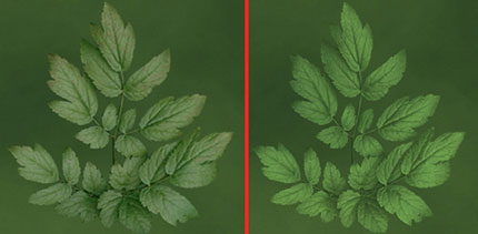
FIG 4.16
Create two new layers and place them below the original leaves layer and set to color dodge. We will use these to paint color variation back into the texture. I want to take this a lot further than the original image.
For the first layer, I painted the stalks of the foliage brown and used a darker green with a touch more blue to paint some shadows. A lighter green was used to paint highlights. I used the standard Photoshop brush with a medium opacity. In Fig. 4.17, the new layer is on the left over the background, and on the right, all the layers are displayed.
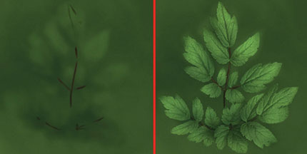
FIG 4.17
At this point, we could easily leave this texture as complete.
For the environment tutorial later in the book, I really wanted more color in the foliage. More specifically, I wanted autumn colors. Using the second layer that we created, I gradually built up a range of yellows and browns around the ends and edges of the leaves. At this point, I was satisfied with the result. Figure 4.18 shows the second paint layer on the left over the background and the final result on the right.
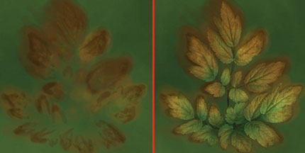
FIG 4.18
I created the other three sets of leaves on the texture sheet in exactly the same way, using reference from different photos. The horizontally tiling stalk element running along the bottom of the texture sheet was created by using the Rectangular Marquee Tool (M) to create a selection.
I then created a new layer and used the gradient tool set to reflected gradient. This applied a cylindrical style shading to define the stalk.
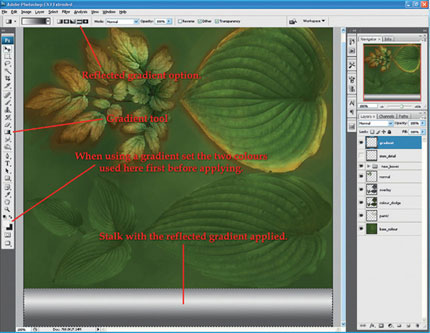
FIG 4.19
I then set this gradient layer to overlay. As it then looked too smooth, I copied a section from another image and stretched it out horizontally over the stem and set it to soft light. This was just to add a bit of noise and variety to the stem. This layer was also tiled horizontally using the offset tool.
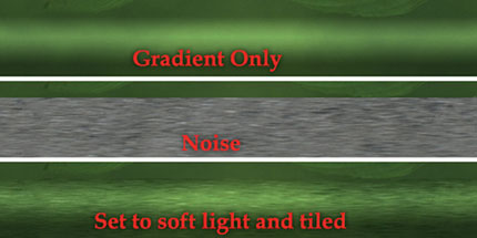
FIG 4.20
The other textures were created in the exact same way. For the dry bush, I extracted the section of tree branches from a photo. I then duplicated some elements and moved them around to fill out the texture sheet more. After this, the background was created. The texture was then adjusted afterwards to blend in with the other textures within the scene.
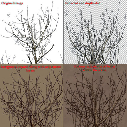
FIG 4.21
The tree branch and foliage were created by using the leaves from the earlier section and taking a section of the bush from the previous texture. Figure 4.22 shows the steps in creating this texture.
First, the branch was rotated, so it starts in the bottom left corner. I then started to duplicate and move, rotate, and scale the sets of leaves and place them all over the branch.
I tried to get as much variety as possible by tweaking the lightness, hue, and saturation of some copies as I went along.
After I was happy with the result, I dropped in a background. This time the foliages blend mode is set to normal, so I did not use the cloud filter on the background.
The final steps were to duplicate the leaves and desaturate the image. Then I set it to multiply to get some shading and contrast into the foliage. Another common thing I do with foliage is to duplicate the final version and place this layer beneath the original. Then blur the copy. The reason for this is that if you use a file type or game engine that uses mip-maps, it will prevent the alpha and diffuse maps having issues such as a “halo” effect on the textures.
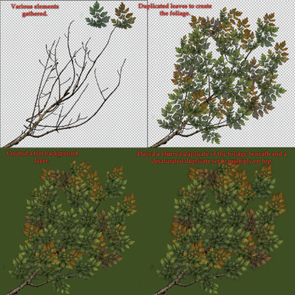
FIG 4.22
Finally, there is a slightly different technique I use for creating grass.
The two bottom sections of the grass texture were created by using photographs as a base as in the previous examples. The other types of grass were created entirely in Photoshop.
First, create a new file with the dimensions of 512 × 512 pixels. Go to the main menu > Edit > Preferences > Guides, Grid, Slices & Count. Under the Grid option, set the Gridline every to 256 and pixels. You can also change the color if you wish. I have set mine to red.
If the grid is not appearing, you can toggle it under View > Show > Grid or by pressing Ctrl + H.
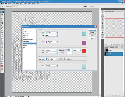
FIG 4.23
The grid should now be displayed over your texture, dividing it up into four sections of 256 pixels square. This tool is very useful when creating texture sheets as you can ensure all the elements are the correct resolution. I intend for most of the grass to fit inside a 256 pixels square.
Then using the pen tool lay out some curved paths that will be used later as the grass, I tried to emulate the way grass grows with the flow of the paths. To use the pen tool, simply left-click on the image to start a path. Left-click and hold elsewhere to create a new point. You can then adjust the curve of the line by moving the mouse. Then keep repeating this process until you are happy with the amount of paths. You can adjust the path’s anchor points after they are created using the direct selection tool. This is in the same area as the path selection tool. Hold the LMB to access it.
In Fig. 4.24, you will notice I started the paths near the base of the bottom left quadrant. This was because when stroking the path, the Simulate Pen Pressure will be checked. This option will create a tapered line for the grass from bottom to top. The blades of grass should be thickest at the bottom and taper to a fine tip, so by starting the paths below the area we want to have the thickest will give the desired result.
To do this, select the paths with the path selection tool. Then right-click and choose stroke path or go to Edit > Stroke… This tool takes the options from any tool in the drop-down list. For this, I used the brush tool. Make sure Simulate Pen Pressure is ticked and then press OK. Figure 4.25 shows these options.
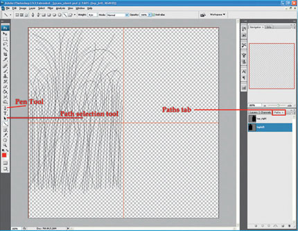
FIG 4.24
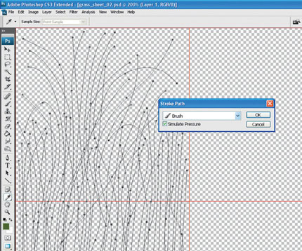
FIG 4.25
The end result should be similar to the grass on the left on Fig. 4.26. To finish off the grass, I used a soft airbrush with a low opacity to build up a gradient on the bottom of the grass. Then with a standard brush on a medium opacity, I manually painted some highlights onto the blades of grass.
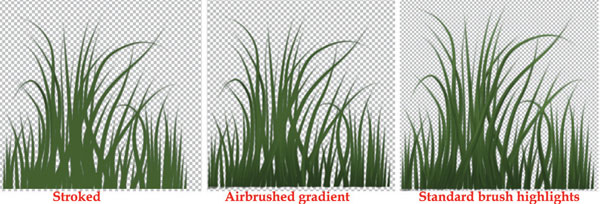
FIG 4.26
This concludes the work on our diffuse textures.
Always experiment using different methods, blend modes, and photographic reference.
Next, we’ll have a look at modeling vegetation.
Creating vegetation for games using alpha maps usually means the geometry can remain quite simple. You only need a group of planes with some simple modeling, letting the textures do all the work.
A good approach to creating vegetation models is to look at the “flow” of the plant or how a plant or tree grows. Also pay attention to the overall silhouette. This will determine the form of the mesh and how components will be placed together to create the overall shape to achieve a realistic natural look.
In Fig. 4.27, I did a quick paint over of a variety of trees to show how they differ in the way they grow. The blue lines represent the “flow” of the foliage or how it grows on the branches. The red lines are the growth patterns of the trunks and branches. I use this approach to breakdown the shapes into simpler forms before I begin modeling the tree.
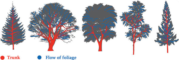
FIG 4.27
This approach of breaking a complex object down into simpler parts also works well for plants. In Fig. 4.28, I demonstrate this. On the left is the reference. In the middle are quick sketch attempts at breaking down the shape of the leaves and growing pattern of the plants. Finally, silhouetted images of the final models are on the right to show how this technique has been applied.
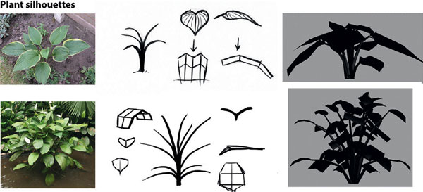
FIG 4.28
We’ll start with the grass models.
Create a square plane and apply the grass texture sheet to it and planar map it. Then using the slice plane tool, divide up the different grass elements as shown in Fig. 4.29. Then duplicate the plane four more times. The idea is to delete all except one grass element on each plane. The end result will be each mesh consisting of only one type of grass. You should end up with five types.
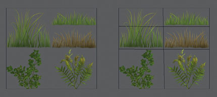
FIG 4.29
In Fig. 4.30, on the top two grass meshes, I duplicated the polygon and rotated it 90° to create crossed planes. Then the two planes were combined into one mesh. This is the most common and basic grass model used in games. It is very cheap and can be duplicated a lot within a scene to quickly create dense areas of grass.
This model was taken a step further in the bottom two examples on Fig. 4.30. Slice Plane was used to add in some additional edges to the plane. These new edges were then used to add some bends on the polygons. The example on the right is a combination of this method and the crossed plane method to create a really dense patch of grass.
You can make the grass models as complex or detailed as you like, by using a few different textures or adding extra edges to create smoother more detailed shapes. In current games, the methods shown here are usually enough.
The more detail you add, the less efficient the models will be when they are placed thousands of times in a scene.
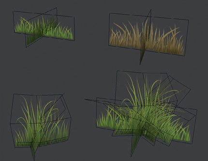
FIG 4.30
In Fig. 4.30, I have cut around the texture to reduce the amount of unused transparency on the mesh.
This is a widely used optimization as unused transparency on the surface of the mesh will still be calculated when rendering even if it is not visible.
In Fig. 4.31, the area highlighted in red is the area I have removed. This makes the mesh more efficient to render, especially when there are a lot of instances of the model in the scene.
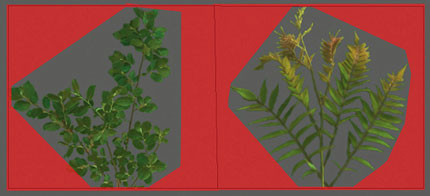
FIG 4.31
I then used these extra vertices to add depth to the model by pulling them back. The meshes were then duplicated and positioned to act like crossed planes.
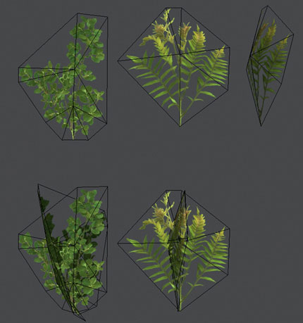
FIG 4.32
The next models are the selection of smaller plants. They are very simple models and designed to be cheap and used numerous times. These models were created in the same way as the grass. Three of them also have stems.
These were created by moving, rotating, and scaling the vertices of a three-sided cylinder. You could start with a cylinder with a few height segments or use slice plane to add in some edge loops as you need them.
The leaves on the far right plant have more modeling detail on them. The cut tool was used to add extra geometry. The vertices were then adjusted to create a central crease in the leaf.
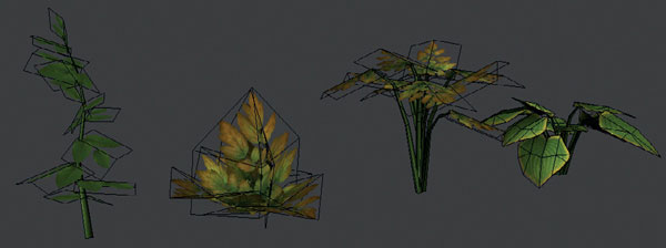
FIG 4.33
The next models created were the bushes. The starting point was a square flat plane. Another was added with some extra edges, and the central vertices moved out to create some depth.
I then built the bush out from a central point on the ground using duplicates of these two meshes. The model on the right is much cheaper and intended for use on the edges of the scene.
I could have cut around the bush as an optimization from the initial state before I duplicated them as mentioned earlier to reduce the surface area of unused transparency.
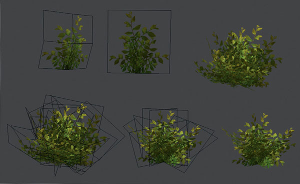
FIG 4.34
As an example to how flexible vegetation meshes are, I assigned the dry bush texture to this model. It looks a lot different even though it’s the same mesh. This is easy to do as a texture swap as long as the texture layout is similar; this will mean you won’t need to remap anything.
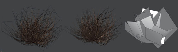
FIG 4.35
The final model we will look at is the tree.
Start with a cylinder and delete the polygons on the top and bottom. Then using the slice plane tool, add some edge loops.
Next, use these to model the bottom of the trunk. Duplicate the mesh, scale it, and position it high up on the original mesh. This will form the basic shape of a branch. These steps are shown in Fig. 4.36.
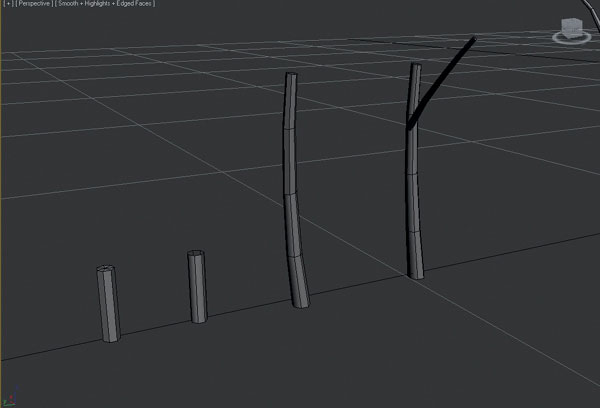
FIG 4.36
Duplicate the trunk and branch meshes a few more times and use them to create the tree. Figure 4.37 shows the final version of the first-pass tree model.
After placing all the branches, I spent a few minutes modeling more to create some variety in the model.
The next step was to combine all the meshes together using attach and then to stitch the branches into the main trunk mesh. Use the cut tool to create the edges on the trunk to match the branches. Delete the faces on the trunk where the branch will connect. Then use weld or target weld to stitch the vertices of the trunk and branches together.
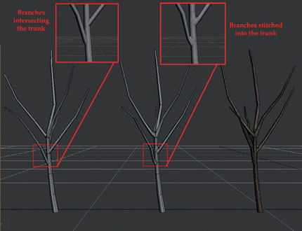
FIG 4.37
Attaching the branches to the trunk is a personal preference of mine as I prefer to have the branches and trunk as one solid mesh. It is ok to leave the branches intersecting the trunk as in the version on the left of Fig. 4.37. I just prefer the look of the lighting and shading on the stitched version in the center.
When you are satisfied with the tree model, next we need to unwrap it.
Cylindrical mapping was the main technique used, paying close attention to keeping the seams facing inwards into the tree, so they’ll be hidden by foliage later.
Figure 4.38 shows the final unwrap of the trunk and branches. I tried to have as few UV shells as possible. There is one for the trunk and one for each branch.
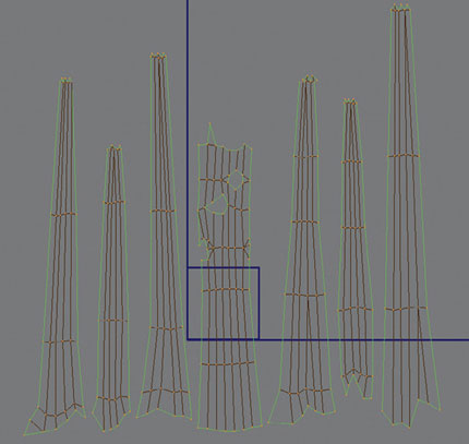
FIG 4.38
Now that the tree itself is complete, it’s time to look at the foliage. Just as we did before, I created a flat plane and one with some extra detail. I then used many duplicates of these to fill out the foliage on the tree placing them around the branches. Moving, rotating, and scaling them as I went. Figure 4.39 shows the two foliage meshes used on the left and the final tree on the right.
When the foliage was complete, it was attached to the trunk to create one mesh. The pivot point was then centered to the object and snapped to the bottom vertices at the base of the trunk. This will allow for easier placement of the tree in the environment later.
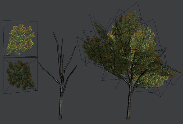
FIG 4.39
As it is still not possible to build current game environments full of thousands of trees, many cheaper solutions are used to make environments seem fuller than they actually are. One of these methods is the use of tree walls.
Tree walls are flat planes or simple meshes used on the edges of an environment. They usually consist of one texture that may tile. Figure 4.40 shows a flat plane with the texture applied.
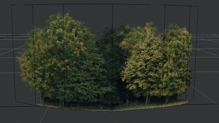
FIG 4.40
Figure 4.41 shows a similar mesh, but a section of a cylinder has been used to give the model more form.
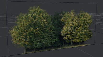
FIG 4.41
As always, this concept can be taken one step further. I would personally use the previous tree wall methods if they were to be placed a good distance away from the game play area. They are great background fillers, but they don’t hold up well to close inspection if a player is beside them.
One solution is to fill out the tree wall with other meshes and create a more expensive version that will sit well just off to the side of the game play area behind other assets. Figure 4.42 shows a good example of this.
It was created from most of the meshes created in this tutorial.
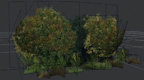
FIG 4.42