David Griffiths
Note from this book’s author: David has taken a step-by-step approach for this tutorial. If you get stuck at any point, feel free to grab the 3ds Max file from the Web site and move on. Remember that you’ll really benefit only if you do the whole build yourself, so try to solve your own problems instead of jumping ahead. You will improve quicker and will be a stronger artist at the end with the ability to troubleshoot future problems.
Some of the original (consecutive) build files have been removed in the text to speed up the build process for you (Files 23, 24, or 77, for example); please follow directly to the next instruction in the text.
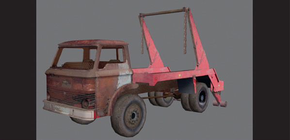
Create a plane for each view of the vehicle. A front, back, side, and top, so four in total. A good tip to get accurate proportions and avoid distortion is to create a plane the same size as the image. Ensure you are using the same measuring system throughout the project—for example, the metric system.
Once created, freeze the planes by going to the Display panel > Freeze > Freeze Selected and make sure to uncheck “Show frozen in grey” in the Display Properties, which is under the Freeze menu. Turn on the Poly Statistics in the viewport to keep a tab of the polygon budget (by typing 7 on the keyboard). Create a new layer using the layer manager, by clicking on the Manage Layers button on the main toolbar. ![]()
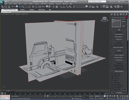
FIG 5.1
Then click on the top-left button on the layers pop-up window, Create New Layer. You can rename this layer to whatever you like, but I have just left it as the Max default name. Make sure there is a black tick to the right of the layer name to show it’s the current layer. If not, click on the white box to make it the current layer. Every newly created layer will by default be the current layer.
FIG 5.2
In the Top viewport, create a box that will automatically be assigned to this layer. In the materials, give the box a color and set the opacity to something like 70% so that you can see the blueprint planes through the box. Turn on edge faces and give the wireframe a color different from the material color. I have chosen black.
I created the box in the Top viewport and positioned it roughly around the cab.
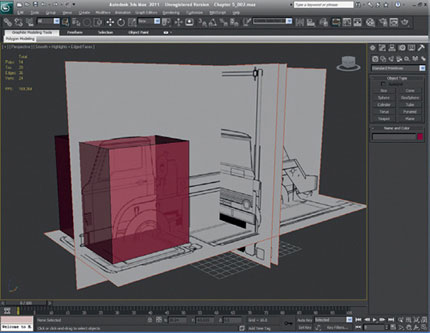
FIG 5.3
Right-click on the box to bring up the Max menu and convert the box to an editable poly. Scale the box, moving the vertices, so it fits approximately around the truck cab.
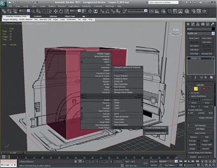
FIG 5.4
Using the Slice Plane tool, start splitting up the box along the z-axis with subdivisions at key intervals and then follow the details of the cab in the pictures. If you can’t see the splits that you are making and you want to see all the edges, then make sure that you have the edges unchecked only in the Object Properties menu. Sometimes it is good to toggle edges on and off.
You should end up with something like Fig. 5.5:
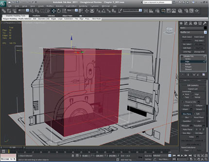
FIG 5.5
Split the cab directly down the center and delete one half of it. Now, start moving the new vertices of the remaining half that you have made to fit the shape of the cab more accurately.
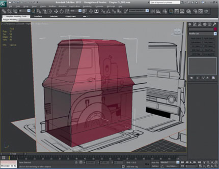
FIG 5.6
Now, we need to make it more rounded by using the chamfer tool. As you can see, I have chamfered the outer edges once to make it more rounded, but it still needs much more work to make it rounded, and we need to tidy up the new edges that 3ds Max has given us.
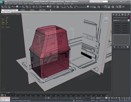
FIG 5.7
I have added more chamfers to the edges of the cab, and I have tidied up and moved the vertices to better interpret the roundedness of the shape. The edges can’t be rounded too much because that would give us too many polygons, so look for something that is fairly smooth, but still low enough on detail.
Here you can see that I have used the same principle to round the center section of the cab in the same way, keeping the detail low while maintaining the curves.
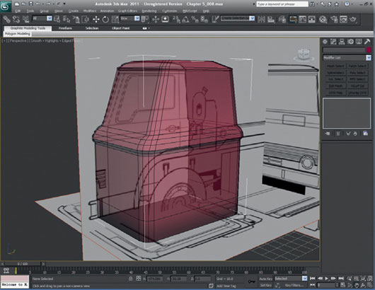
FIG 5.8
Now, split the roof to create the same amount of detail in the form of the curve.
When adjusting the splits in the roof, you will need to move the vertices around to fit the shape of the cab. You can do this a number of ways: by moving the vertices by hand or scaling them. If you scale them, you might want to consider mirroring your cab model to make the scaling easier, as 3ds Max will by default scale from the center.
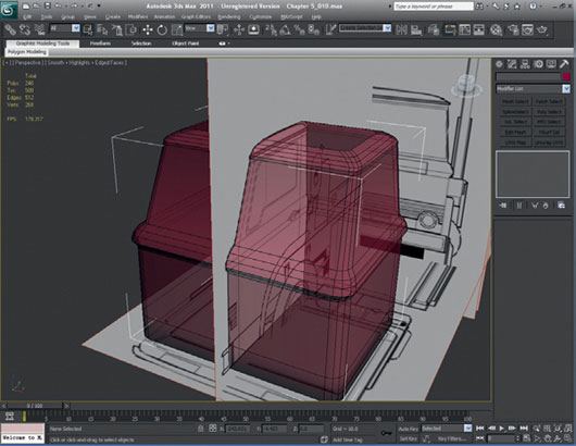
FIG 5.9
The cab needs a few subdivisions along the world x-axis so that we can add more curvature to the roof and the rest of the body in general. I have deleted the other half of the cab again, as this is the way I like to work, although you could use the mirror instance so the other half is modeled at the same time.
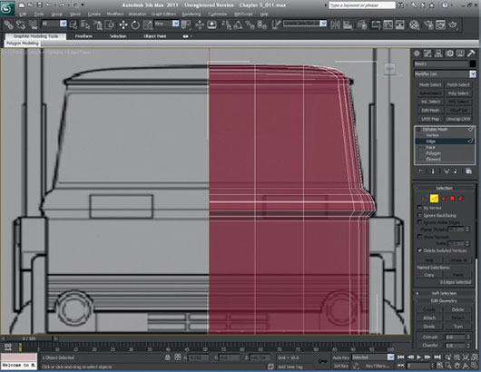
FIG 5.10
With the subdivisions added, move the points to fit the curve of the roof more precisely. I recommend that you keep going through your entire cab model and keep refining it because this is very important in 3D modeling. Adding new vertices, edges, and polygons can get out of hand if you don’t watch what is happening.
Next, let’s move the vertices in the new divisions we have made on the world y-axis to curve the front and the back ever so slightly.
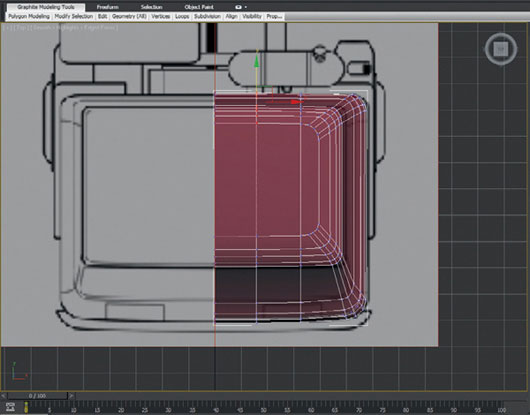
FIG 5.11
We need to add some more divisions along the world y-axis so that we can create more detail in the side of the cab.
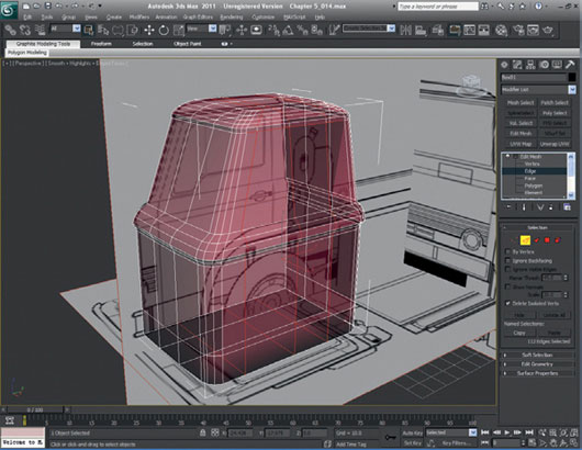
FIG 5.12
The cab has a lip just underside the roof, which needs to be modeled, and we can extrude that from the preparations we made earlier.
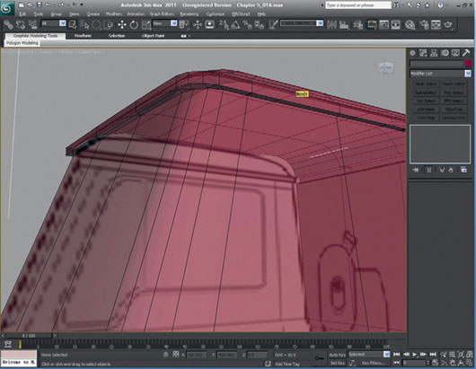
FIG 5.13
Let’s look at creating some of the other features of the cab such as the wheel arches. We need to create a shape that we can use as a Boolean to give us the shape. Create a cylinder. I have created one with 28 sides.
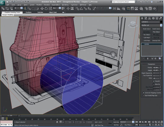
FIG 5.14
Delete 3/4 of the cylinder so that you leave the quarter of the shape that will make up the wheel arch.
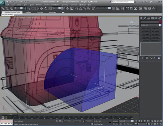
FIG 5.15
Extrude the outermost edges of the new wheel arch so that they extend past the bottom of the cab and out of the back of the cab. It is important that the edges go beyond the boundaries of the cab for the next Boolean.
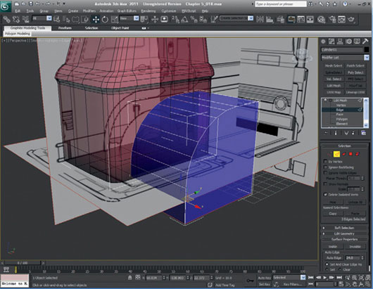
FIG 5.16
To begin to make the shape of the start of the wheel arch, we need to create a Boolean with the cut/refine function. First, select the cab, go to Create > Compound Object > Boolean, and then select Cut > Refine from the Parameters menu. Then, click on “pick Operand B” and select the 3/4 cylinder. It will disappear leaving the cuts we need behind.
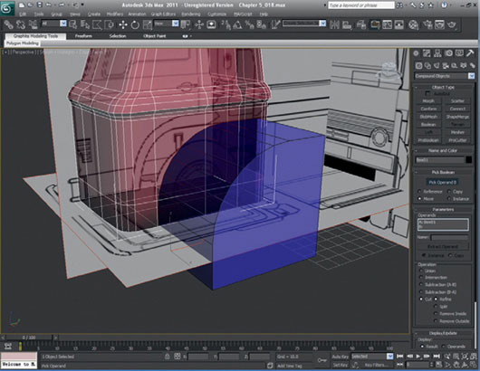
FIG 5.17
Now, we can delete the polygons left in the Boolean function to create a hole, which will become the wheel arch.
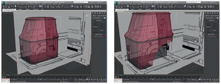
FIG 5.18
Select all of the edges from the curve of the Boolean that we just created and extrude them to create a lip, which will form the protruding lip of the wheel arch.
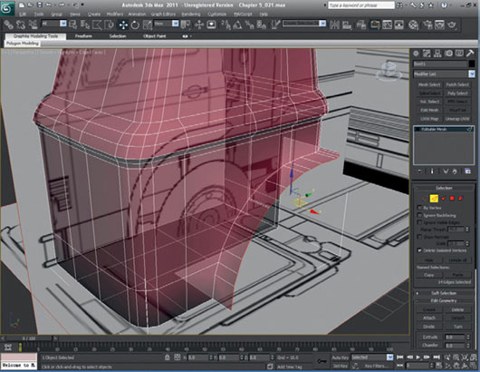
FIG 5.19
Some of the extra lines and vertices that we created when performing the Boolean will have to be cleaned up. It is important to keep the model as neat and tidy as possible. We need to look for the extra vertices and edges and decide which ones can be deleted or welded. Obviously, if you delete vertices, you will create holes, so use something like Target Weld and Move instead.
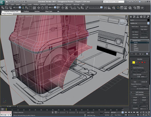
FIG 5.20
We also need to create a few new edges to the wheel arch so that we can preserve the curve and keep it regular.
The wheel arch needs to be extended further out from the cab body. Select the edges at the back of the cab for the wheel arch and extrude them.
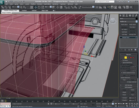
FIG 5.21
The edges of the wheel arch need to be curved around. This is done by scaling the outer vertices. The form of the arch needs to be altered slightly, so a little refinement is required.
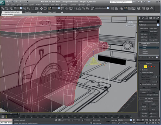
FIG 5.22
We now need to start looking at the detailing on the doors and windows. I create these by using the Divide Edge function, but you could select polygons and use Slice if you prefer. We could Boolean these details, but most of the information for the door and front window could be put in manually; feel free to use the Boolean function for them if you’re more comfortable with that tool or whichever method you’re most comfortable with. Remember to remove any unwanted detail after each Boolean transformation to keep your model neat and efficient. You should now have the seam of the door detailed as shown in Fig. 5.23.
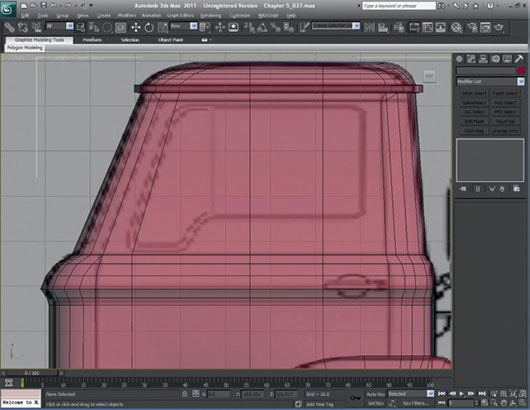
FIG 5.23
Select the edges of the door and add a chamfer modifier to them.
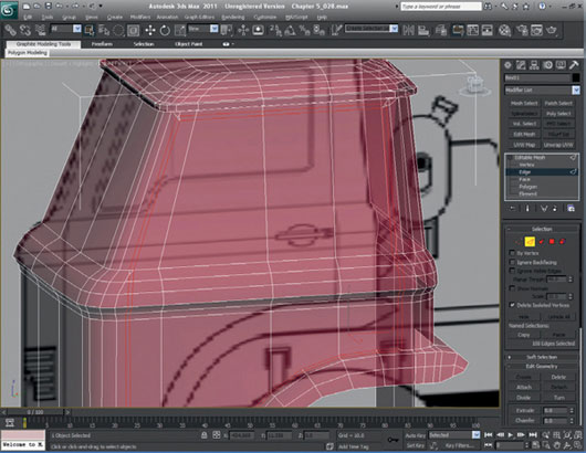
FIG 5.24
Clean up the undesired vertices that the chamfer function has given you. Some of the edges also need to be tidied up slightly to keep all the lines and edges flowing across the model. Try to keep a neat topology when creating any new faces or edges, and try to make sure that any new details are constructed from edges that neatly loop around the object
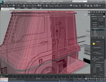
FIG 5.25
Select the polygons that were created by the chamfer command and extrude them inwards by approximately 0.8. These polygons will be used to create the start of the door seam.
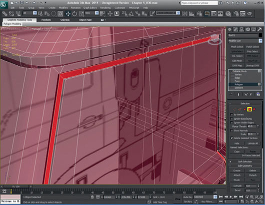
FIG 5.26
Now weld all the inner vertices of the seam together to create an inner groove. Your door seam is now complete.
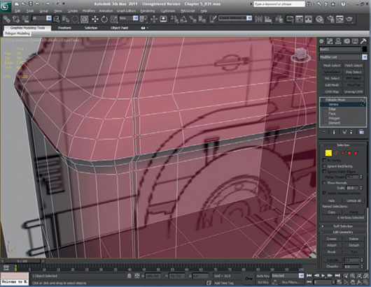
FIG 5.27
Detail the seam of the front window, using Divide Edge (or Slice or whatever you prefer) as before. To do this accurately, you will need to jump into the Front viewport and outline the edges of the glass.
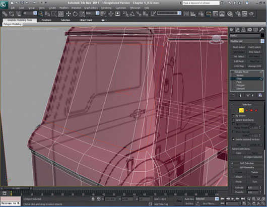
FIG 5.28
Chamfer the window edges and clean up the result.
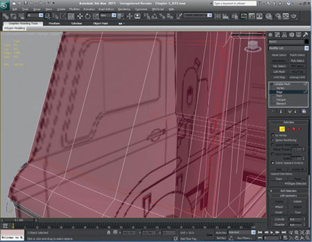
FIG 5.29
As with the door, we need to extrude the polygons that the chamfer has given us. This time, instead of extruding polygons inwards, we extrude them out and then weld the outer vertices. This step will give us the raised edge required.
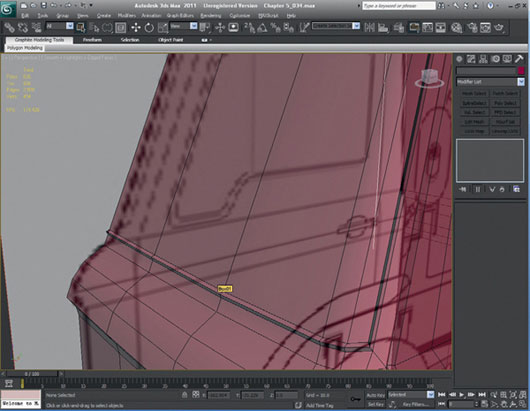
FIG 5.30
Next, we need to create the door window with the help of a Boolean shape. First, create a box in the Side viewport with a couple of subdivisions. Manipulate it until it fits the window shape as shown.
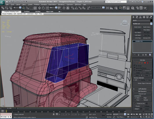
FIG 5.31
Now, we need to create the Boolean using cut or refine and clean up the result edges, vertices, or polygons.
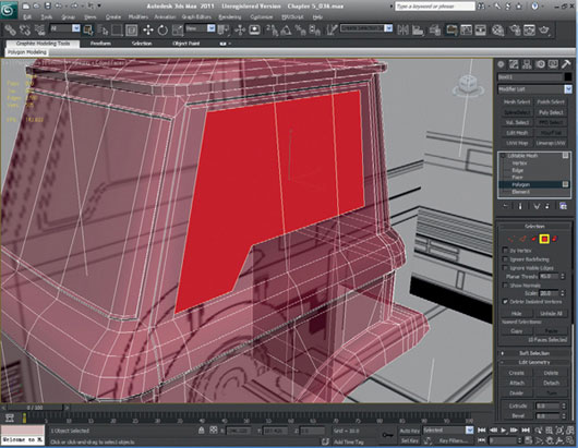
FIG 5.32
We need to create a recess or lip similar to that in the real photograph or blueprints of the cab door. To do this, extrude the selected window polygons and then scale them to create the required indentation.
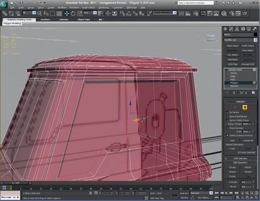
FIG 5.33
We will now create another edge in the door window all round the sill that we just created. To do this, divide all of the polygons right through the middle. To make sure that 3ds Max splits them in the center, turn on 3D snap with “midpoint” checked. Once created, the new midpoint vertices need to be scaled slightly outwards. You can use the scale tool or move the points manually. I’ve gone through and selected all the edges so that you can see clearly what I have created.
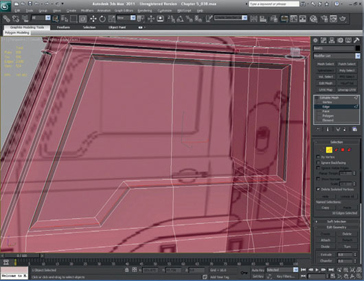
FIG 5.34
Now we need to repeat the same process for the rear windows. These will be created exactly like the door window, so just follow the steps again. You should end up with something like Fig. 5.35. Don’t worry too much if yours doesn’t match my example exactly—it doesn’t have to be perfect.
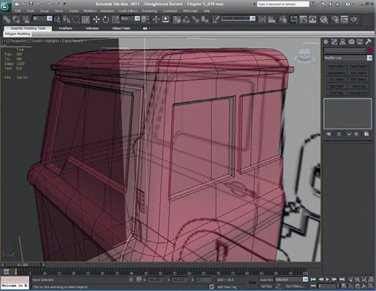
FIG 5.35
Looking at our progress so far, the side windows we created look a little too square, making the truck look slightly fake or a bit too low poly. It would be a good idea to round them off slightly by chamfering the corner edges. We should probably only do this once to keep the polygon count down on the truck. Feel free to make the curves more complex than I have if you want a better-looking vehicle, but remember that this is a low-poly vehicle.
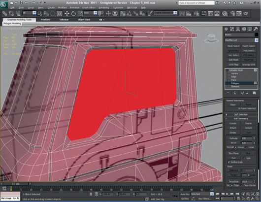
FIG 5.36
As before, we need to clean up any extra vertices created and make sure that all the edges are clean and run round the object smoothly. I have chosen to make some of the edges visible, although this isn’t strictly necessary. Unchecking “Edges only” in the Object Properties helps you see all the edges that define an object and therefore to see clearly what edges, if any, are causing problems.
Repeat the same chamfer process on the rest of the windows to make the windows look a bit more smooth and realistic.
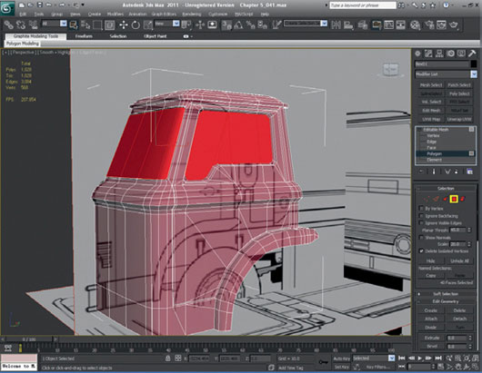
FIG 5.37
We need to do the same recess-type structure around the front wind screen. This usually wouldn’t be modeled, but because the final model won’t have windows, we must show it to keep continuity. This recess lip is created the same way as for the other windows. I have selected the polygons here so that you can see what I’ve done.
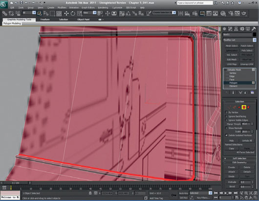
FIG 5.38
Now, we can start to look at the front lights. We need to Boolean a cylinder into the cab. The cylinder should be approximately of 12 sides (I wouldn’t use fewer than twelve sides, but if you would like more fidelity and a smoother look to the light, use more sides; but always go up in twos).
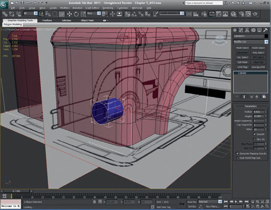
FIG 5.39
The cylinder has now been Boolean’d from the cab. The Boolean was again set with the cut/refine option. As always, you have to clean the mesh. This is a common task to perform after every Boolean transform you perform.

FIG 5.40
The new polygons that have been made for the light can now be extruded inwards so that we can start making the concave form of the headlight.
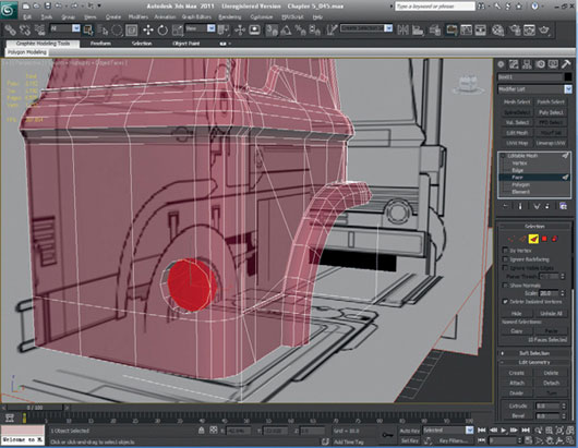
FIG 5.41
Once the polygons have been extruded, they must be made planar. An easy way to do this is to convert your model into an editable poly (if it isn’t one already) and use the Make Planar function located in the Modify panel when a polygon is selected. In this instance, I used Make Planar on the y-axis.
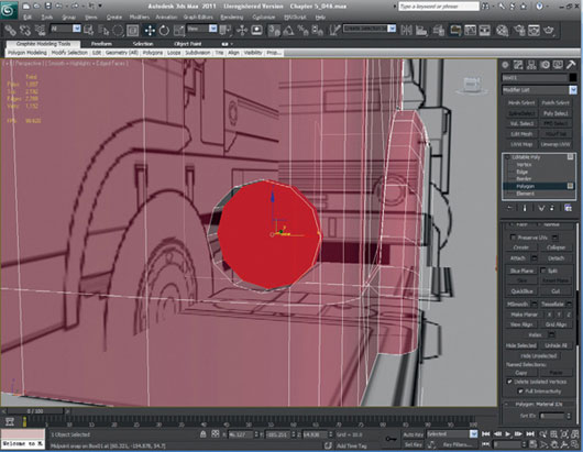
FIG 5.42
We need to scale these inner faces and extrude them again. Once the new sets of polygons have been extruded, we need to scale those, too.
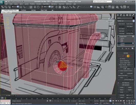
FIG 5.43
Extrude another set of faces, but instead of scaling them, select all of the vertices and collapse them into one using Collapse.
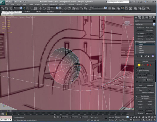
FIG 5.44
Let’s take a break for a moment and see how our truck is progressing.
It’s important to stop every now and again when you are modeling, to get a drink or move around, or just to take a look at your progress. It’s so easy to select one or two vertices too many when collapsing and take out a few that you didn’t mean to. If you notice the mistake quick enough, it won’t do much harm, but if you fail to spot it because you’re so busy detailing specific areas, it can cause you a bit of pain and some lost time. Remember to drink plenty of water when you are trying to learn something new and take a 10-minute break every hour or so—it really does make all the difference.
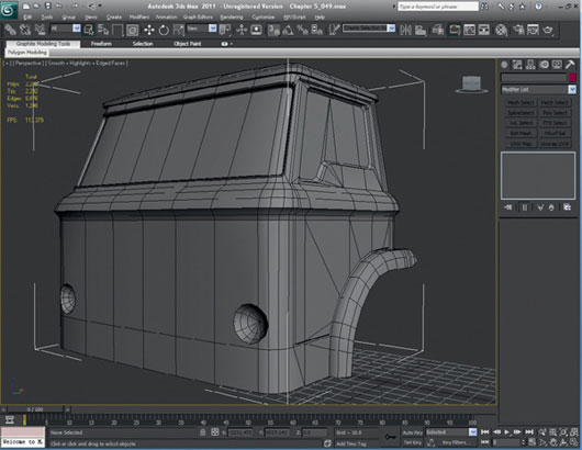
FIG 5.45
Let’s take a look at the back of the cab where the engine would be. On the photographs, we can see that the cab appears to have been cut out to give the engine and gear box more space. The cab on this particular truck also has a cover over the engine, so it can’t really be seen. Some of the engine details from this part of the truck need to be guessed or researched further, as we don’t have accurate blueprint information for this area. Make the cuts to accommodate the engine as shown.
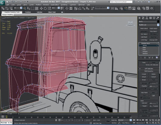
FIG 5.46
Even though the engine cover is a separate object on the real truck, we will make it a part of the cab, as we don’t want to spend the polygons to make areas like this separately. You may have noticed at this point that the blueprints don’t completely match the original photographs; this is because the blueprints incorporate some of the other details of the other skip truck (from the photos) including the fuel tank and generator on the back. Next, we need to extrude these edges to build this form using scale on the vertical axis to get the edges or vertices level along the bottom edge.
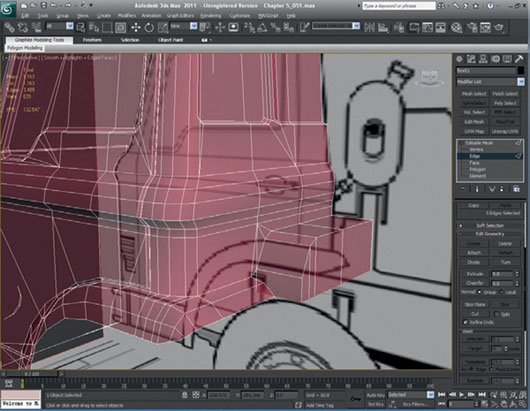
FIG 5.47
Let’s move onto the truck’s front bumper. Once we have done this, we’ll move on to the back of the truck. Obviously, the truck still needs lots of work, including an interior, but if we complete the back of the truck before the interior, we will get a better impression of how many polygons we have left to use for the interior. What may happen is that we go over budget anyway, even if we try to be conservative. If we do, we just have to trim polygons at the end of the build—this is quite common. If this does happen, always keep a copy of your higher polygon model for future use.
Let’s get on with the bumper. To start, extrude the polygons that we made at the very start of the truck build to form the rough bumper shape.
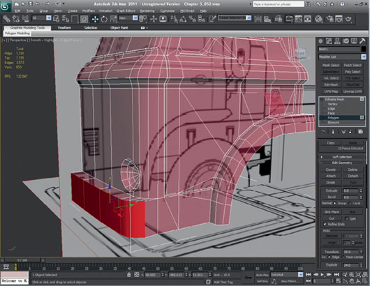
FIG 5.48
Move the vertices of the extruded polygons to match the bumper on the blueprints a little more closely. We can do this most effectively in the Top viewport.
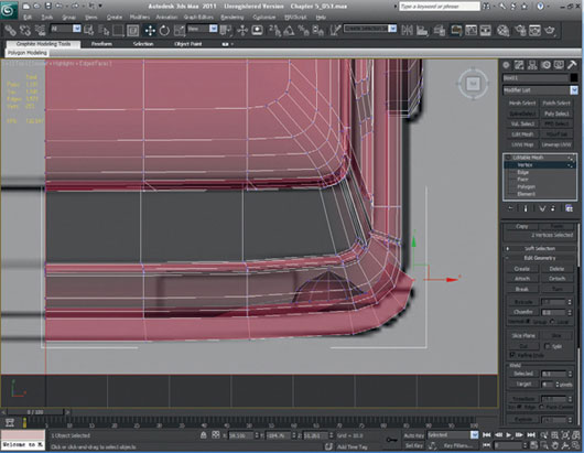
FIG 5.49
We need to improve how the bumper attaches to the cab. Show edges and turn the edges on the ends of the bumper. Make sure that you also make them visible to help you to do this.
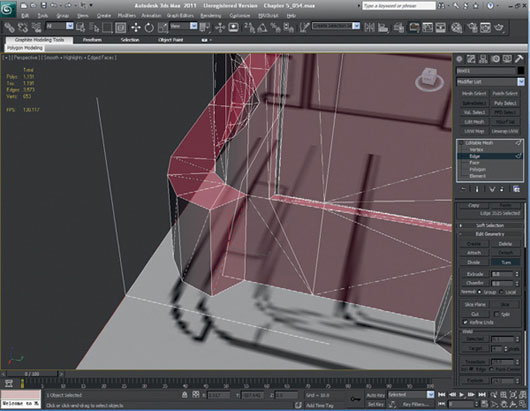
FIG 5.50
Next, we will delete the end polygons and create some new ends that are much closer to the blueprints.
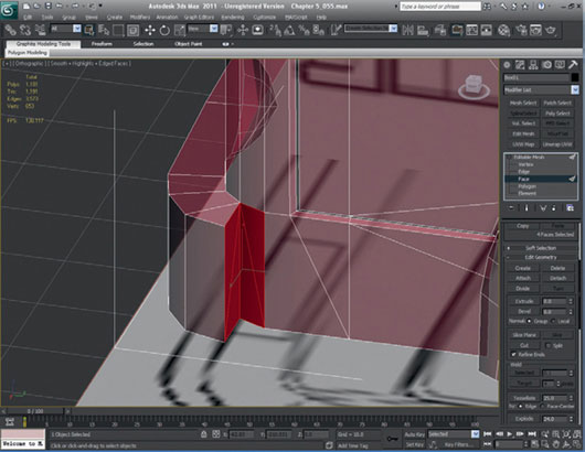
FIG 5.51
We need to build the bumper ridge that runs along the top and bottom of the bumper. Select the polygons along the front of the bumper.
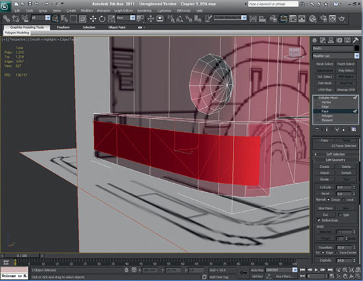
FIG 5.52
Now, extrude and scale them so that you end up with a depression. We will leave the truck’s cab there for the moment and move onto working on the back. Remember to take a break, grab a drink of water, and have a look at what you’ve done so far.

FIG 5.53
Create a new layer for the back of the truck and freeze the cab layer or turn it off for now. Next, create a box and scale it to resemble the main bed of the back of the truck and taper the back.
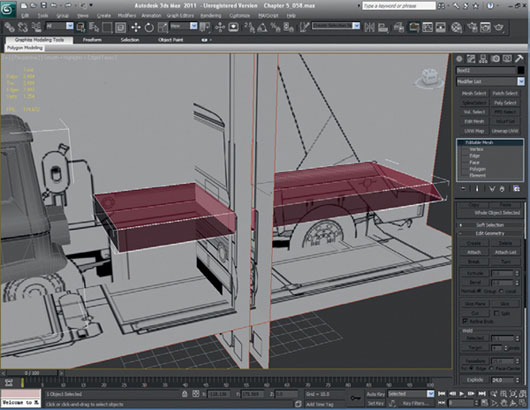
FIG 5.54
Start to split the back up into the component parts like we did for the front cab, adding all the cross sections that we will need.
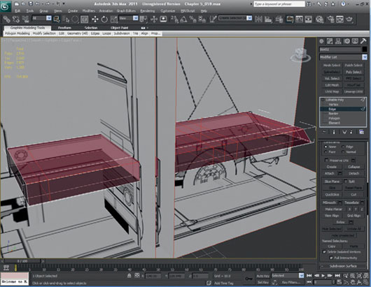
FIG 5.55
Now, we will extrude and shape the trailer arms that come up from out of the trailer base. Again, we are using only Extrude, Scale, Move, and a little Rotate, just as we have before.
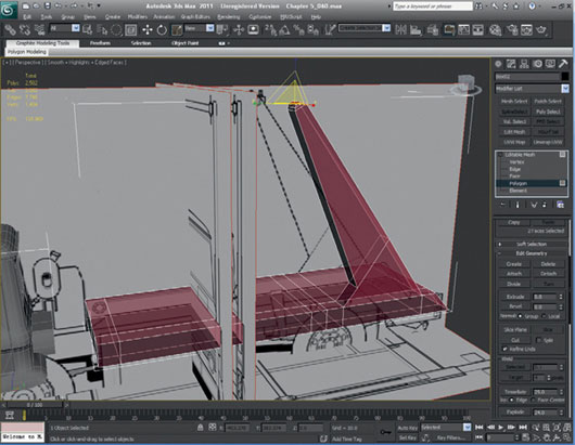
FIG 5.56
As you can see, the top of the arm is too thick, so detach this, make it thinner, and then reattach it.
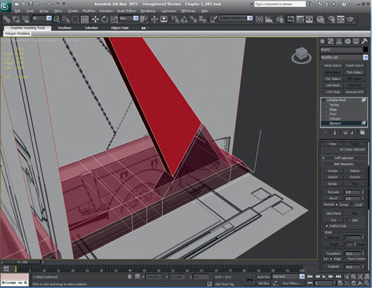
FIG 5.57
We need to fuse the model together properly, so divide edges and weld the vertices. Create new polygons to fill in the holes we just created.
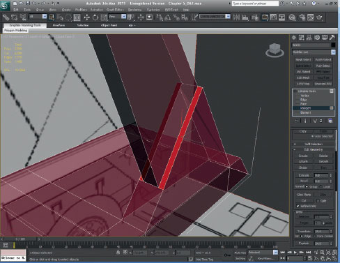
FIG 5.58
The back of the trailer needs the rest of the structure building. To do this, make some more divisions at the bottom so that you can extrude the necessary face.
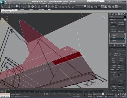
FIG 5.59
Now, the faces can be extruded and shaped to make the back structure and that will ultimately house the rear lights.
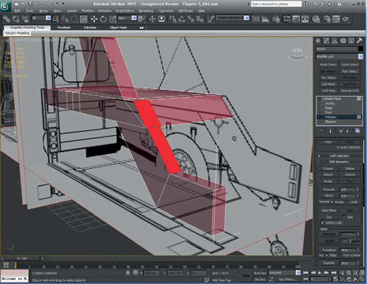
FIG 5.60
The end of the rear lights arm needs to be capped as shown in the blueprints. We can do this by extruding the sloped faces out and then extruding the side faces as well. This will need cleaning up and welding when completed to make it neat and tidy.
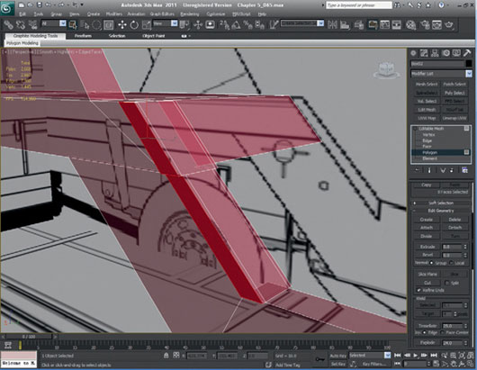
FIG 5.61
The capped end has now been cleaned up.
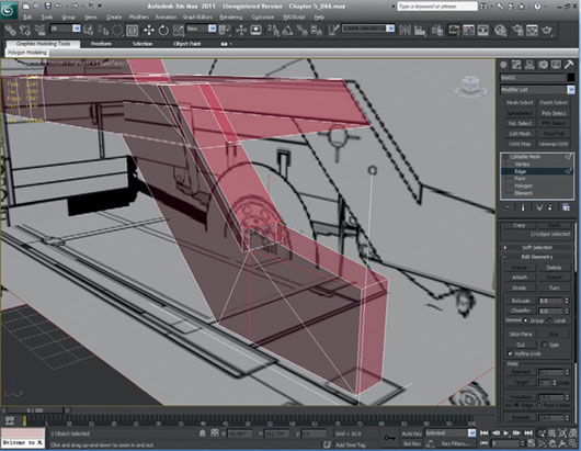
FIG 5.62
Now, we will start adding more detail to the trailer back. First, make an inner edge to lower the height in the middle by extruding the interior faces downwards.
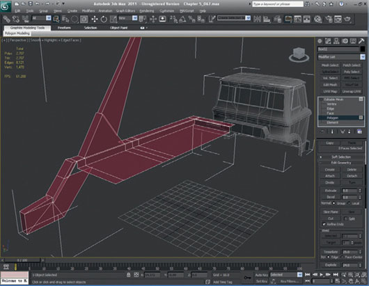
FIG 5.63
As with the inner lip that we just created, we need to add more detail to the arm, as it has to have a thickness for the hydraulic system. Detach the arm and alter the width so that you can build an outer lip. Leave the arm detached because this will be refined later on.
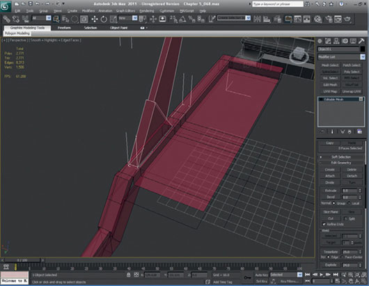
FIG 5.64
Refine the edge for the inner lip down the back of the rear light arm, as this will eventually make the gap for the arm to move in. Tidy up the vertices and edges and alter the lip widths so that they match the thickness of each other. Make sure that the model still lines up with the blueprints. You may find that you need to move some of the vertices to realign your model again.
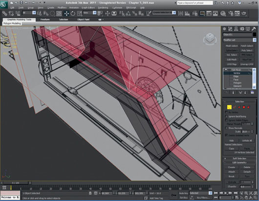
FIG 5.65
Once you are happy with the divisions that you have created for the trailer lip, select the inner faces that need to be copied and moved downwards to create the recess. When you have selected the faces, move the faces down with the Move tool while pressing the Shift key. This step creates duplicate faces.
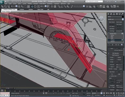
FIG 5.66
You can now delete the original faces. Once deleted, create the faces that make up the sides of the inner recess.
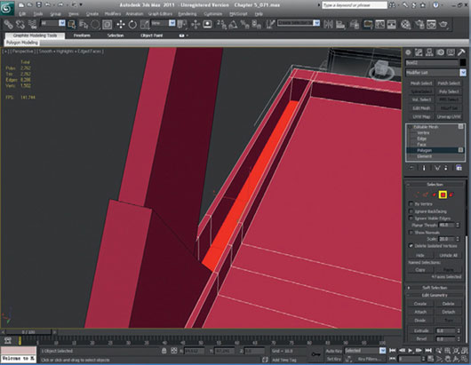
FIG 5.67
Your trailer should now be starting to take shape.
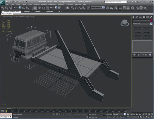
FIG 5.68
The trailer back now needs to be closed up so that it looks like the back of the real skip truck. Make sure that the truck bed is roughly the same height as in the blueprint. Extrude the back edge down to create a vertical step, extrude it again to create an angled step, and then make a final extrude to create the last step down.
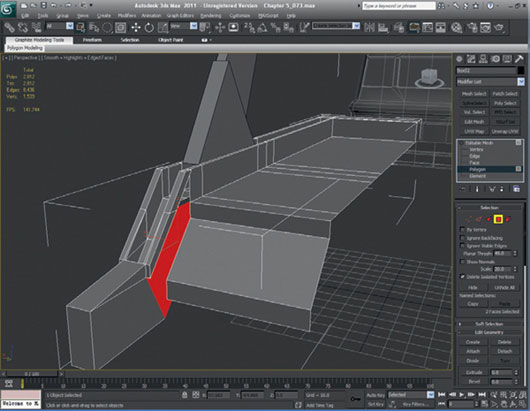
FIG 5.69
Now, the new back can be integrated properly with the rest of the back. You need to fill holes to make the rear of the truck solid. Because this is difficult to see in orthographic blueprints, I suggest that you use your artistic eye in conjunction with the photographs and interpret the back the best you can. Take a look at this file to see how I tackled the problem. Note that I have tidied up stray and unwelded vertices. I have also deleted the faces underside and reduced the polygons by welding vertices that I no longer needed.
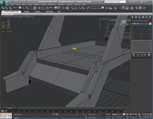
FIG 5.70
To make the back more realistic, I have added a slight recessed section where the rear light arm flows into the back. This was easily created by extruding the inner face inwards and then deleting the polygons at the top and creating new polygons, which were welded together.
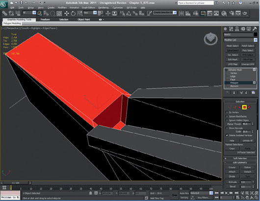
FIG 5.71
Now, we can start to look at the underside of the truck. It must be created from imagination because we don’t have much information for this area from the reference photos. This bottom will be fairly simple. It is created by extruding edges vertically and horizontally so that we can enclose the gap at the bottom. Look at Fig. 5.72 to see how I finished off the bottom area. Make sure that whatever you create is tidy and that all vertices are welded. Don’t worry about the underside too much. There is no plan for the truck to be flipped over, so it doesn’t have to be perfect; just keep it clean and simple. Here’s my interpretation of what the underside of the trailer might look like.
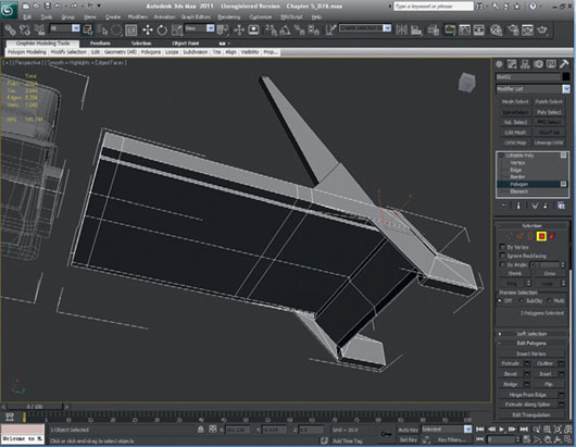
FIG 5.72
Now, we can start modeling the trailer details. Start with the mudguard. First, move the two edge loops in the model to where the mudguard should be placed. On the underside between the two splits, create another division.
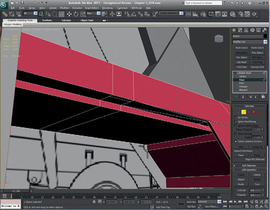
FIG 5.73
Extrude the face downwards to create the outer edge of the mudguard. Once extruded, shape the faces to resemble the mudguard shape. Split the mudguard in half on the inner face.
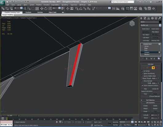
FIG 5.74
Pick the polygon that has been split on the outer back edge and extrude it until it reaches the first lip. Delete the inner poly and weld the mudguard inner faces to the inner lip. Tidy up remaining polygons that are no longer needed.
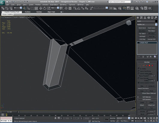
FIG 5.75
Select the inner open edges and extrude them roughly halfway to the middle of the trailer. Close the holes and weld all vertices.
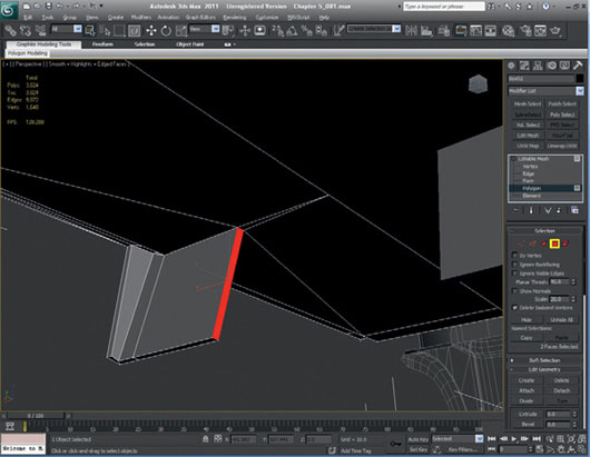
FIG 5.76
Select the back face where the rear lights will eventually be. Extrude and scale the face to create an edge all the way around and then extrude the face once inwards to create the rear light recess.
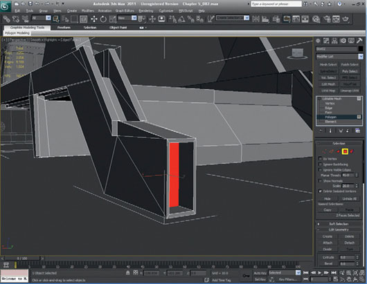
FIG 5.77
Create a cylinder with 12 sides and no divisions and place it where the stabilizer arm is going to be attached to the main trailer. Make it the same thickness as the trailer frame.
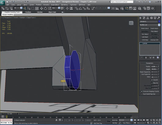
FIG 5.78
Copy the cylinder and move it to the inside of the trailer frame. Once you have both cylinders placed, join them to the trailer. For this step, I am going to use the Boolean union operation and then clean up the results.
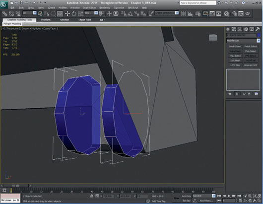
FIG 5.79
The finished brackets have now been merged onto the trailer to make one object. I extended the inner bracket with the inner top faces so that it looks a little stronger.
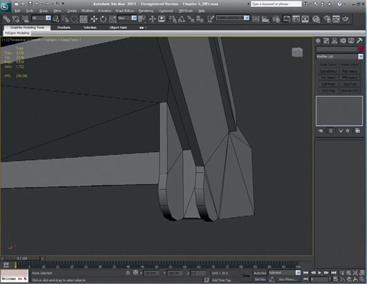
FIG 5.80
We will now make the stabilizers. Create a new layer and create three circles using the Spline menu on that layer.
Convert one of the splines into an editable spline and attach all of them together.
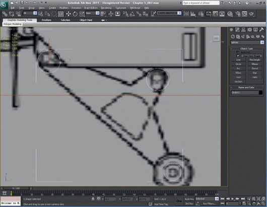
FIG 5.81
Click on the vertex function in the Spline Menu and use the Refine button to add vertices to the circles at points where they will need to intersect with each other.
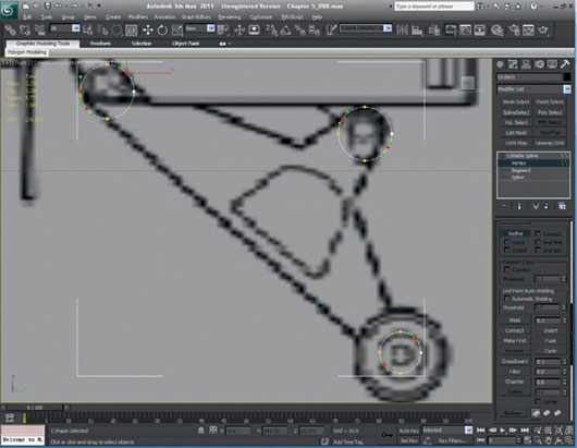
FIG 5.82
Delete the curves that are inside the points of intersection.
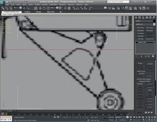
FIG 5.83
Use Create Line to attach the shapes together. Make sure the 2.5 snap is turned on and vertices are checked.
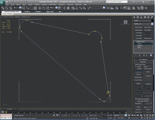
FIG 5.84
Use the Refine button again to add points to create the right-angle shapes. If the vertices are curved, make them a corner point by right-clicking on the vertex and selecting Corner. Weld all the points together.
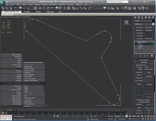
FIG 5.85
Extrude the shape using Modify > Modify list > Extrude. Make sure that Cap Ends is checked. Move the extruded shape into the right position. It will be easier to see what you’re doing if you switch to the Perspective view for this.

FIG 5.86
Reduce the poly count on the stabilizer by cutting polygons from the curves of the semicircles in the model. Use any method you like to do this—Editable Poly or Editable Mesh work equally well.
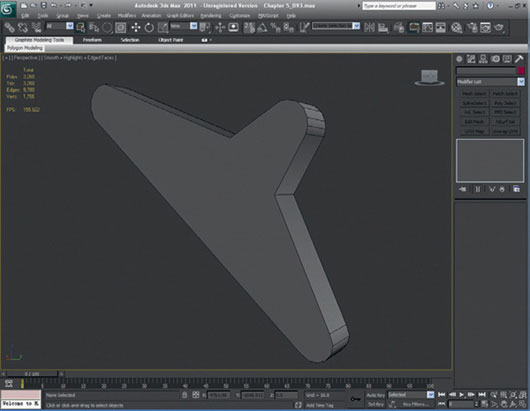
FIG 5.87
Create a box and Boolean it from the stabilizer. You need to Boolean the box from the arm that sticks out, so you can add the hydraulic arm. The hydraulic arm is simply two cylinders. You can probably get away with using six segments in the hydraulic arms for a low-poly object, but again, if you want the model to look a little better for your portfolio, feel free to use a little more. Remember that you probably won’t see this detail on the finished model, so don’t get too carried away with it.
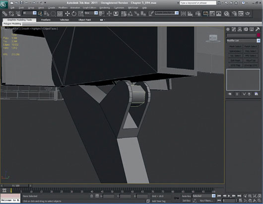
FIG 5.88
Make sure that the inner faces on the hydraulic arm are deleted, as you will never see these in the render.
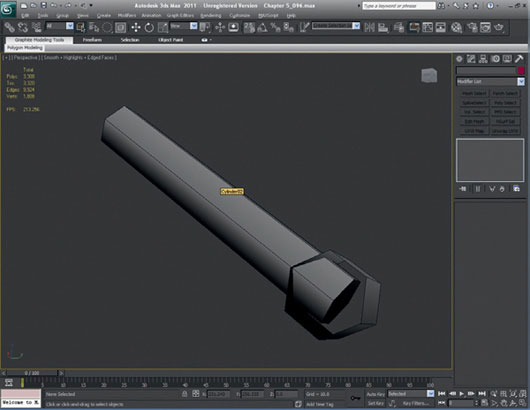
FIG 5.89
Attach this arm to the stabilizer. Create the little stabilizer wheels for the truck using cylinders of no more than 12 sides. Attach the wheels to the stabilizer arms.
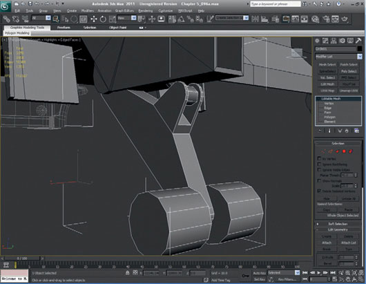
FIG 5.90
You may have noticed that the stabilizer arm really needs a hole or channel built into the trailer to allow it to move, but because this will never be seen, I have omitted this detail. Feel free to model it if you feel that you need to or if you plan on being able to see underside the truck. This detail can be added in the texture to make it at least look like it has a channel built into it.
Now, we can move back to the main trailer arm. Unfreeze the trailer layer, select the bottom edges of the arm, and extrude them. Divide the edges in the center and shape the vertices to where they would hinge on the trailer.
Divide the edges once more to give the bottom edge an L shape. Clean up the edge and the polygons that are not required. Fill in the bottom of the arm.
At this stage, move some of the vertices in the channel we made, where the arm can move. The bottom of the channel underside the trailer must be slightly adapted to allow the arm to hinge in the hole, but if the arm never moves, it’s not terribly important.
At this point, I think it is a good idea to go through the trailer model again and make sure that the file is nice and clean and that all the vertices that should be welded are welded. It is a good idea to remove polygons that you consider to be no longer relevant to the model and just generally tidy it up after a mini-critique.
On the trailer arm, the ends of the struts that we created need to be rounded off slightly. This can be done manually by dividing the edge and moving the vertices to make it appear smoother. Also, the arm still needs to be modified slightly to resemble the trailer arm at the bottom, where it is hinged. The bottom needs to be lifted, and we have to create a lip that is present at the bottom. We can do this by dividing the top edge of the arm and then detaching the arm hinge at the bottom.
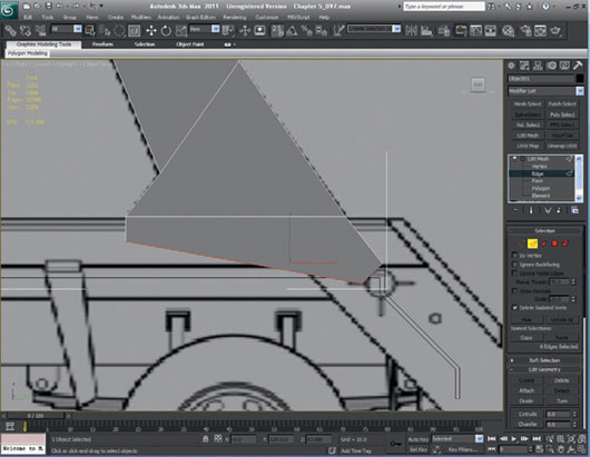
FIG 5.91

FIG 5.92
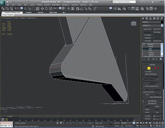
FIG 5.93
Reattach the bottom hinge part of the arm, then Boolean the part of the arm that is attached to the hydraulic arm. This is exactly the same process we used on the stabilizer.
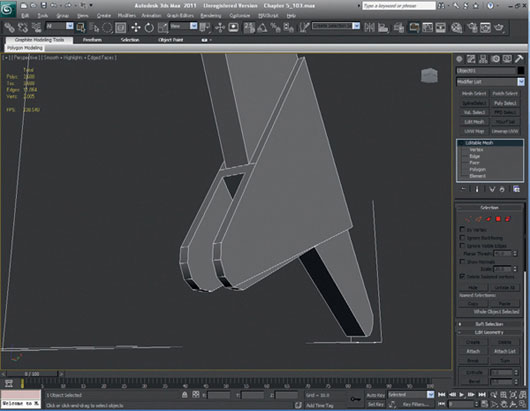
FIG 5.94
Let’s build the main hydraulic arm. This again is simply a 12-sided cylinder. Before we create the cylinder, we must pull the top edges down to make the inner lip thinner.
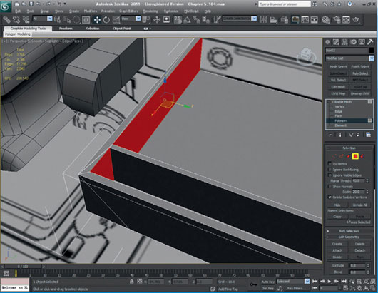
FIG 5.95
Create the cylinder with 12 sides. Once created, extrude and scale the faces nearest the trailer arm and extrude them again to make the end piece of the hydraulic arm.
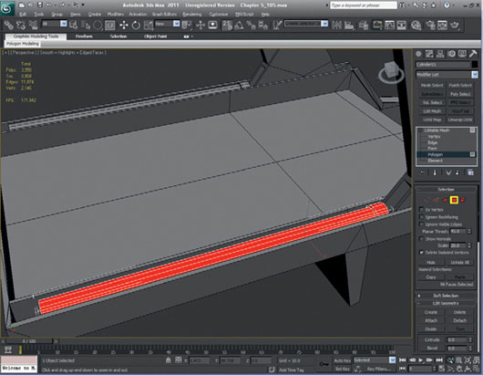
FIG 5.96
At the top ends of the trailer, extrude the faces and make the shape conform to the blueprints. The extruded polygons also need to be refined slightly and welded.
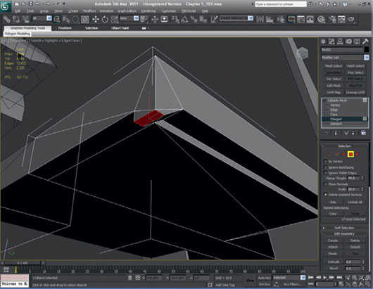
FIG 5.97
The bottom of the trailer needs an extra detail ledge that will rest on the truck chassis. This is done by creating an edge that runs from the front to the back; then the face can be extruded.

FIG 5.98
Create a new layer so that you can start a basic model for the truck chassis. This should be fairly simple, as we really don’t have the polygons to spare for it. First, start with a box that will make up one side of the chassis and mirror it to create the other side.
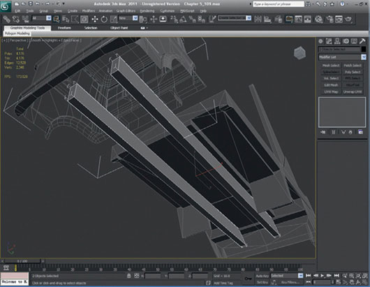
FIG 5.99
Now, we will create a wheel from a cylinder. The cylinder should be set with 16 sides with height segments of 5. This setup makes the wheel fairly smooth when rendered but keeps the poly count reasonable and manageable. Move the wheel into position.

FIG 5.100
Delete the back face of the wheel, select the other side of the wheel, and scale the face to give the tire part of the wheel a more inflated look. You can (if you wish) set the smoothing groups so that you can see the tire section more easily to distinguish it from the wheel hub.
Select and scale the center polygons again to start creating the wheel hub. When you have made the rim, scale and extrude the already-selected polygons again continuously until you have created the hub. Use the photographs and the blueprints as the guide.
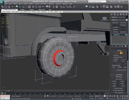
FIG 5.101
Select the hub part of the wheel and detach it. Then select the outer edges of the hub and extrude them backwards toward the inside of the tire.
Select the extruded polygons created from the outer hub and then flip the normals to create the inner rim.
Reattach the hub to the tire and then fill in the whole left in back of the wheel. You can do this by either manually creating new polygons or selecting the hub outer edge and extruding it to make a set of polygons, which you could weld to the tire’s open inner edge. The front wheel now is complete. At this point, you can mirror the wheel to complete the set.
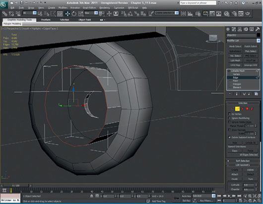
FIG 5.102
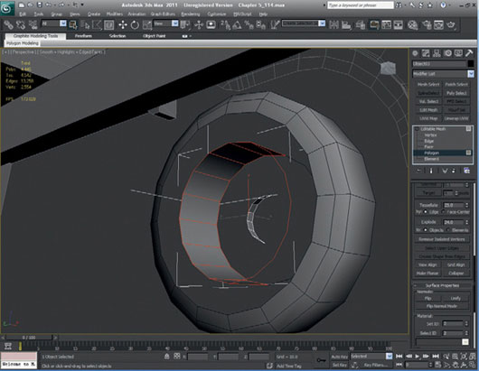
FIG 5.103
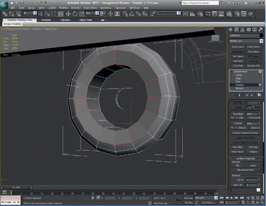
FIG 5.104
Next, we will move on to the rear wheels. We can modify the front wheels to make the rear wheels. The only real difference on the rear wheels are the hubs, so we won’t have to make too many alterations. One thing to note is that the rear wheels are in sets of two. Select the front wheel, clone it, and move it into position by using Select > Shift-drag.
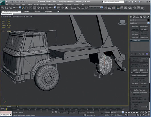
FIG 5.105
Select the innermost ring of faces on the hub and pull the polygons back.
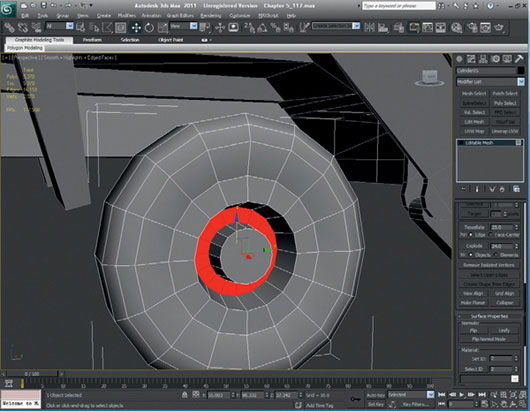
FIG 5.106
Select the inner edge of the hub and scale it outwards to make it wider than it currently is. Do the same with the next edge, continuing inside the hub.
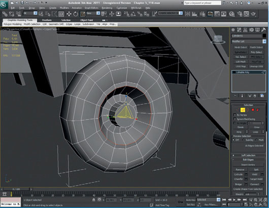
FIG 5.107
Copy the new rear wheel and move it inwards to make the rear wheel a double wheel. At this point, you could keep the wheel separate, but for this model, it will be connected in order to save polygons.
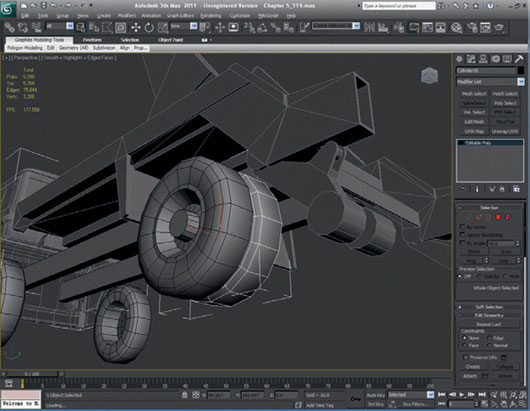
FIG 5.108
To keep the polygon count down, delete all the extra polygons from the hub facing outwards and the inner ring.
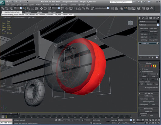
FIG 5.109
Now, delete the opposite face on the outer wheel, but keep the inner hub faces.
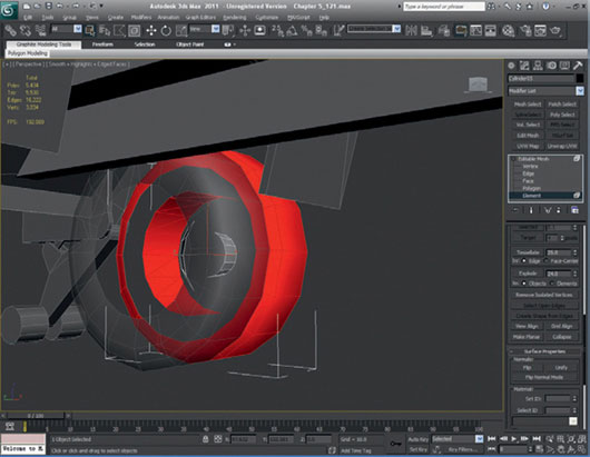
FIG 5.110
Now, we can attach both wheels together to make one double wheel. Weld the inner hub faces to the back of the outer wheel edge. Once this is done, mirror the wheel to complete the set. It would be wise to look over all the wheels that you have created and make sure that they are cleanly built and that all the vertices are welded. Ensure that all of the polygons and normals all look okay. You can also sort out the smoothing groups, if you wish; an autosmooth would be fine for the wheels.
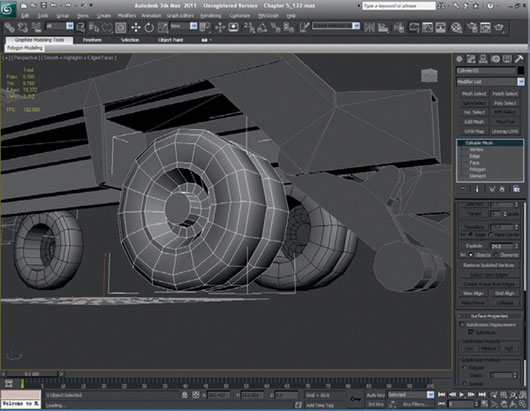
FIG 5.111
Now, we can start to model the suspension. To start this process, create a cylinder with six sides and a height segment setting of 5 to create the rear axle.
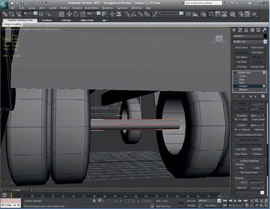
FIG 5.112
Scale the middle of the cylinder slightly to make the starting shape of the rear differential. Scale last two edges in to make the shape slightly rounded.
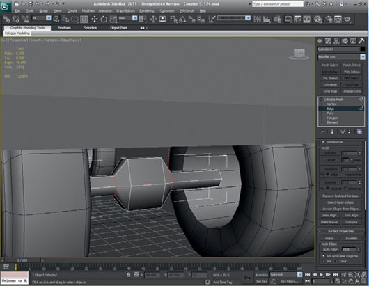
FIG 5.113
Split the center of the differential and scale it slightly to round off the shape again.
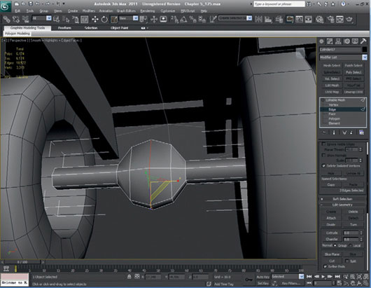
FIG 5.114
Select the inner faces of the differential and extrude them to pull them out. Scale the faces so that they are planar (that is, flat). Scale them again to taper the faces to more of a point.
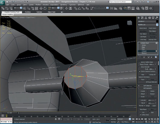
FIG 5.115
Clean up unnecessary polygons from the axle by removing them.
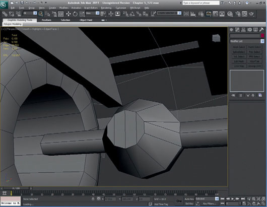
FIG 5.116
Create another cylinder; this time with eight sides, but set the height segment to 0. Move this cylinder to the outer edge of the axle. This is now the brake drum, so it now needs to be mirrored and attached to the axle.
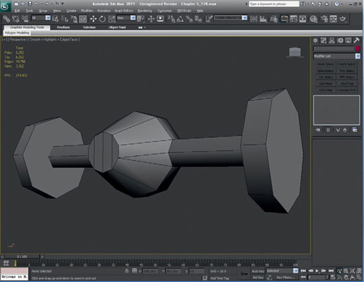
FIG 5.117
Copy the rear axle to the front. Delete the differential (the round chunky bit in the middle of the axle), as the truck is rear-wheel drive. Scale the width of the axle so that the brake drums fit within the front wheels hubs. To do this, move the hubs and the axle at the subobject vertex level.
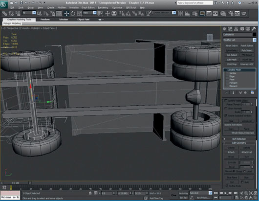
FIG 5.118
Create a box below the rear axle, between the differential and the brake drum. Create it by setting width sections to 5; this will form the leaf springs.
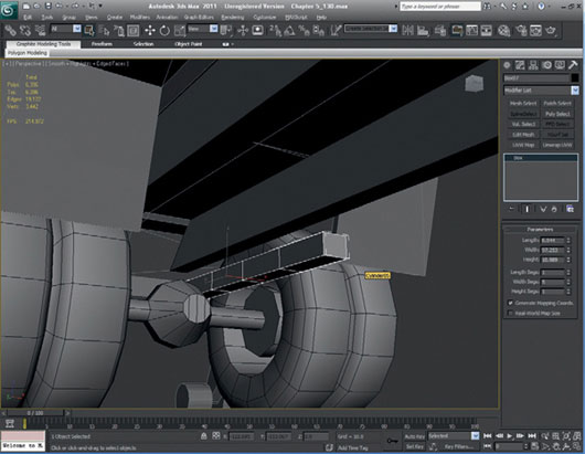
FIG 5.119
Convert the box to an editable mesh and move the outer bottom vertices to make it curved at the bottom.
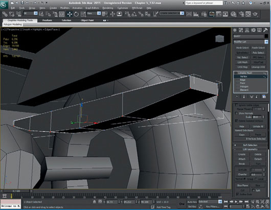
FIG 5.120
Now, with the Bend Modify, bend the leaf spring slightly.
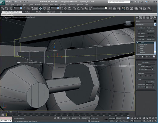
FIG 5.121
Select the center section of the leaf spring, scale the width, and then select and extrude the face on the bottom. Select and chamfer the extruded face’s edges.
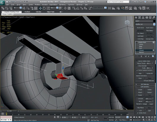
FIG 5.122
Because we altered the underside of the trailer at the rear, we need to make some alterations to the main chassis. We need to add a new division to the edge so that we can move the edge of the chassis up to the rear of the trailer to fill the gap. You can now make the leaf spring larger or smaller to match the blueprints if you didn’t create it at the correct size in the first place.
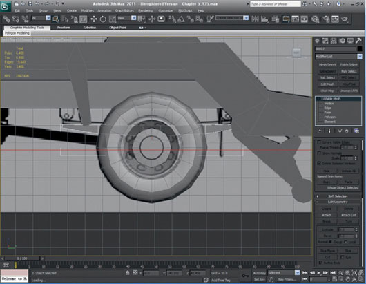
FIG 5.123
The leaf springs need to be fixed onto the chassis with brackets. These will be created using boxes with chamfered ends. You may need to scale the thickness of the leaf spring to fit in the brackets you have created. Attach the bracket to the leaf springs, copy the leaf spring, and then move it to the front. Attach both leaf springs to the chassis, copy them, and then mirror the whole chassis.
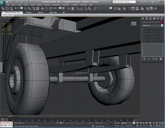
FIG 5.124
Now, we shall look at finishing off the cab. Fill in the bottom of the cab and delete some unnecessary polygons from it. Delete the windows, as the truck in the photos doesn’t have any.
Welding the center loops in the headlights and reducing the polygons around the back end of the mudguards is a good place to start. The roof can also be cut down a little.
Keep removing the polygons that don’t add anything to the overall shape or form of the cab. Often, divisions that we make as we perform specific tasks to make the modeling process easier will need to be removed at some point. If you build one side of an object and then mirror it to complete the build, quite often the center line is a good candidate for this. Have a look through your model to see whether you can spot any others.
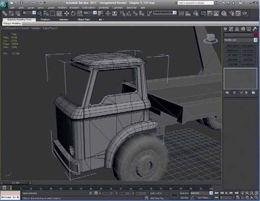
FIG 5.125
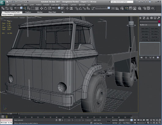
FIG 5.126
Now, we need to fill in the bottom of the cab. Select the edges of the mudguards and extrude them until they meet the thickness of the mudguard.
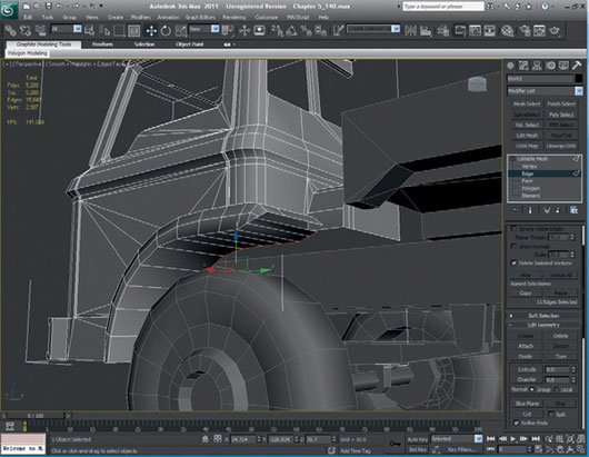
FIG 5.127
Cap the mudguard and then delete the unnecessary edges that were left from the creation of the mudguard.

FIG 5.128
Do the same with the mudguard at the bottom. Also, pull the edges down on the engine cover at the back of the cab. Next, pull the edges down to the top of the chassis.
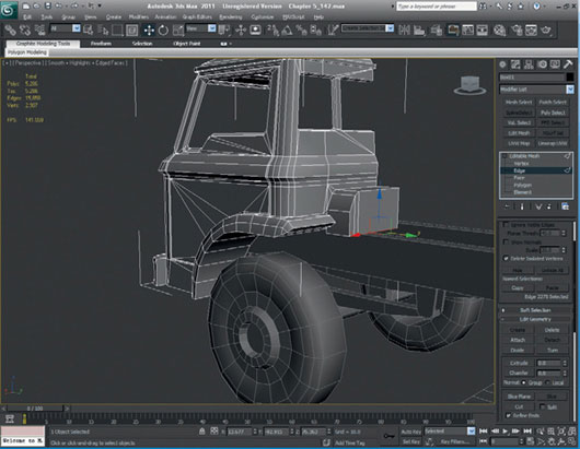
FIG 5.129
Start to fill in the whole underside of the cab. Extrude the outer cab edges and weld the vertices to make a solid closed shape.
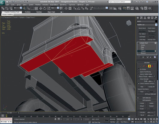
FIG 5.130
You need to incorporate the chassis in the underside construction of your cab model. Take a look at Fig. 5.131 to see how I have closed the bottom of the cab fully. You will notice that I have reduced the polygons slightly and cleaned up some of the faces to make it a neater model.
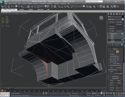
FIG 5.131
So, all we have to complete to finish the cab is a basic interior. We could start the interior off by using the shell modifier; however, I find that for this model, it gives us a very complex interior to clean up, so the alternative is to create it manually. Start by selecting the open edges of the front window and extruding them in, and then extruding again and scaling them larger.
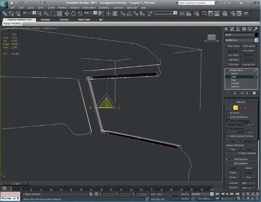
FIG 5.132
We will do the previous step with all of the open edges on all the windows to create an inner shell.
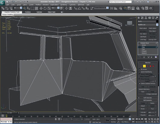
FIG 5.133
Now, we can start to weld and create new polygons from these starting points to fill in the interior. Remember that it should be pretty basic, though.
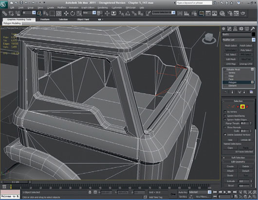
FIG 5.134
We need to build two chairs and a steering wheel and the steering column. These will also be very basic. In fact, they are pretty much made from single polygons. To make them look more detailed, they will be textured, but with alpha maps applied, so that you can see the frame of the chairs and the steering wheel.
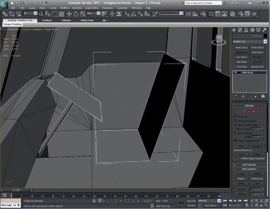
FIG 5.135
With the model nearly complete, we just need to finish off a few remaining details. Create a box-type shape underside the cab to act as an engine and gearbox. We can map this shape with an engine-type texture to make it look more detailed. Once we have modeled the engine/gearbox, we can link up the prop shaft to the rear differential.
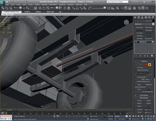
FIG 5.136
We can now add the final touches. Create a six-sided cylinder to make the bar that connects both the hydraulic arms at the top. Create a low-poly bracket box and a cross-section set of polygons hanging down from the bar so that you can map a chain texture to make it look more detailed without using lots of extra polygons. Feel free to add the extra fuel tank and the control box at this point, but try to keep the poly count as low as you can.
The basic model is now complete.
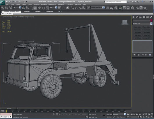
FIG 5.137
Create a new material and load TextureGrid.jpg into the Diffuse slot. You can find this texture in the downloadable scene files Chapter 5CH005.Textures
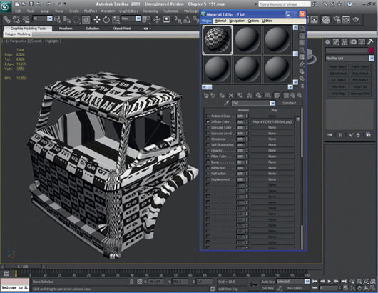
FIG 5.138
Under Modify in the modifier list, choose UVW Mapping and select the box-mapping method.
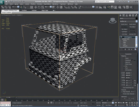
FIG 5.139
Under Modify, choose Unwrap UVW. Open the modifier stack and click Face. Select most of the front faces on the cab and select Planar in the map preferences. If the mapping is from the wrong angle, you can choose Align; for example, if you view the cab directly from the front view, you can select Align from View. If you use the Align using the axis method, use your axis guide in the bottom left-hand corner of the window to help you choose the correct one. This method will be repeated pretty much for the whole of the unwrapping of the truck. So, the rest of the instructions for the unwrapping will be a little less detailed.
Once you have planar-mapped the front faces, open up the Unwrap window by clicking on the Edit button under the Parameters heading and move the new mapped faces away from all the faces in the model. You’re doing this so that you can organize all of the polygons in the model on the texture page in the future.
One important thing is to try to keep the mapping of the faces consistent in size (which includes their aspect ratio). This effort is where the texture grid comes in very useful. Use the grid to make sure that the mapping is equal all over the whole model. There are some circumstances in which you can alter the aspect ratio and size, but as a basic rule, try to keep it consistent.
To actually make the making process a little quicker, convert the cab to an editable mesh or editable polygon and delete half of the model. Now, reapply the Unwrap UVW to the cab and continue with the mapping process. Using the same method that we did for the front of the cab, select the side polygons and move the new faces away from all of the other faces in the Unwrap window. You may have noticed that there are some areas that look stretched. This issue will be rectified when we lay out the maps in a more organized fashion.
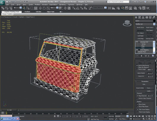
FIG 5.140
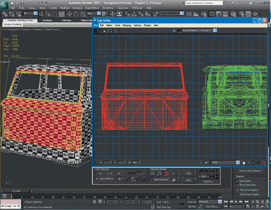
FIG 5.141
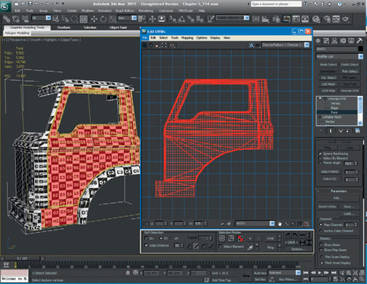
FIG 5.142
Using the same method as before, continue to unwrap the back of the cab and the roof. When working on the lip of the roof, you might want to include the relevant sides that correspond to the front side and back view or you can unwrap the roof as one whole piece to hide as many of the texture seams as possible. Choose whichever method you prefer; for this model, I am going to keep the roof as one whole object.
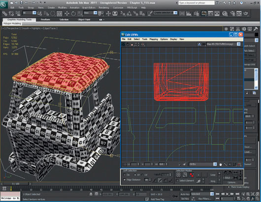
FIG 5.143
You should now be left with the underside of the cab to be unwrapped (excluding the wheel arch, bumper, rear engine cover, and interior at this point). Because we used a box-mapping technique from the outset, you can select the faces of the different parts of the underside and move them out individually in the Unwrap viewport. You may find that some pieces are separate from each other that should be connected, but if you go to the menu at the top and then into Display and turn on Show Vertex Connections, you can see where the faces should be linked. All that remains is for you to flip the faces using the mirror function.
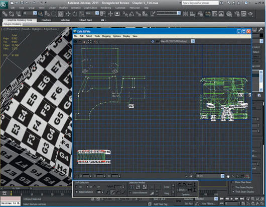
FIG 5.144
Remember that you can mirror both horizontally and vertically or even use the Flip Vertical or Horizontal functions. As you can see from this figure, I have moved the underside of the wheel arch. It was in two parts, but using the previous method, I have put it back together again. I will use this method for the rest of the underside of the cab.
All the underside components have been organized and connected to the relevant parts. You should have only the wheel arch, front bumper, rear engine cover, and interior now remaining to do. Notice that the underside cannot physically be unwrapped as one whole piece, so some of the faces must remain separate. Although this limitation can be annoying, it can also be used to your advantage when placing all the unwrapped faces on the texture page—but this is really done only at the very end of the whole unwrapping process.
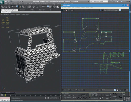
FIG 5.145
Now, we can finish the front bumper and rear engine cover, like we did with the underside of the truck.
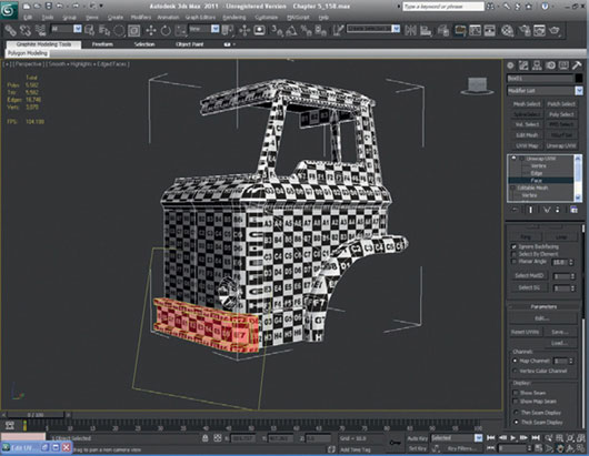
FIG 5.146
And we can now finish the exterior mapping of the cab with the wheel arch. Map this using the cylindrical mapping method. You will no doubt have to alter the texture gizmo. Use the cylindrical mapping modifier from the Unwrapping menu. Remember that you can put the polygons back together if the cylindrical mapping doesn’t work like you want it to.
I have manually straightened some of the vertices on the wheel arch as you can see. Also, notice that I have altered some of the colors for the background and the mesh itself. You can do this by using Options > Preferences. I have turned off Display Seams and Show Grid. I have also performed a mass weld on all the cab polygons in the UVW Unwrap Editor to get rid of unnecessary texture seams. If you do this step, make sure that you don’t weld the wrong vertices. You may have to adjust the weld threshold in the bottom right-hand corner of the Unwrap window higher or lower to achieve the overall weld.
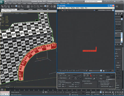
FIG 5.147
We can now adjust vertices around the front corner of the cab to minimize as much of the stretching as possible. It is virtually impossible to eliminate all stretching, but it can be improved or hidden with natural seams or natural shapes in the model.
The interior UV unwrapping should be the only thing left on the cab model. It is a good idea to double-check your model at this point to make sure that you haven’t missed any faces that need mapping; this is a common mistake that is very easily made. If you have rogue faces, I suggest that you fix them now before you go on with the texturing, as they may be harder to find later.
As we have already done with the underside of the cab and the other various parts of the model, our aim here is to organize the interior into as close to a one-piece unit as the model and faces will allow. If you look at Fig. 5.149, you will see that all of the faces for the interior are now laid out by the same methods we’ve used earlier.
It is now time to mirror your cab model. Be sure that when you have mirrored the side, you move the copied model’s texture coordinates away from the original cab. This step makes things easier to stitch together when you put the two sides together. If you look at Fig. 6.153, you’ll see that I have mirrored the cab so that it is now complete again, and the texture coordinates have been reorganized. I am still keeping the cab texture coordinates away from the center of the UV Unwrap window so that they are easy to select once more of the model has been textured. Next, I have changed the background color in the Edit UVW window (from Options > Background Color) just to show you this step a little more clearly.
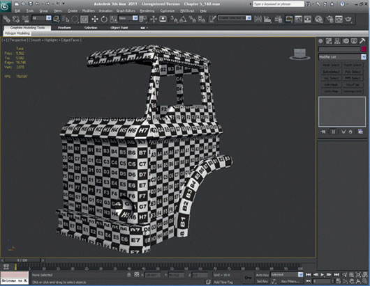
FIG 5.148
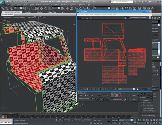
FIG 5.149
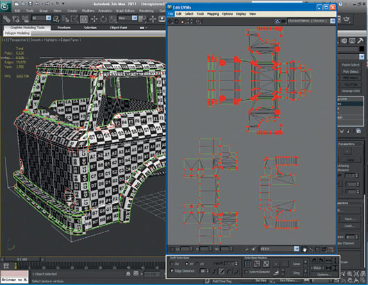
FIG 5.150
Let’s move on to the trailer section of the model. The process is the same as it was for the cab. Start with a cube-mapping method and then sort out all the faces of the trailer by hand.
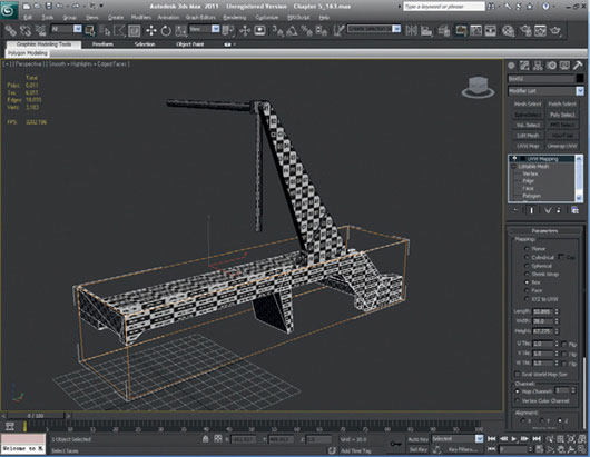
FIG 5.151
Next, I apply the Unwrap UVW modifier to the trailer and start to organize the different faces of the trailer. I have used the exact same methods as for the cab. The trailer in this image has its faces unwrapped.
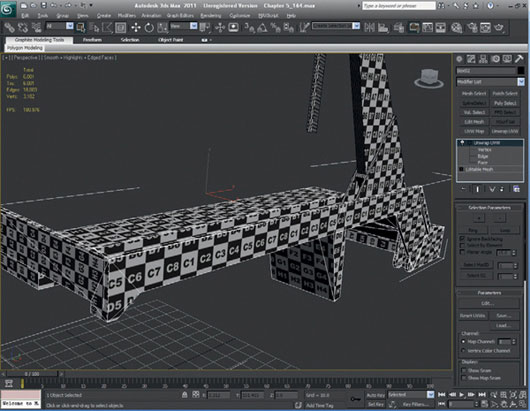
FIG 5.152
Once the trailer polygons have been unwrapped, mirror the model and stitch up the mirrored trailer UV coordinates to the original as in the cab model. Take a look at this image to see the end result.
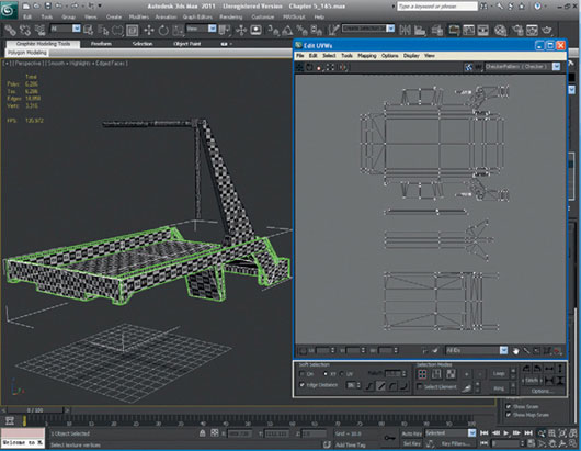
FIG 5.153
Now, we can move on to texturing the trailer arm and the hydraulic arm. Again, the method is the same. The only slight variation is the use of a cylindrical mapping technique for the hydraulic arm. (You may find that some of the cylinders already have cylinder mapping applied to them; these are usually created when you create the cylinder with “Generate mapping coordinates” checked. If this is the case, it just makes your life a little easier!) To map the hydraulic arm, move the end cylinder faces away from the main central cylinder, which makes it easier to select the middle so that you can apply cylindrical mapping to it. Also, move the two boxes and the end cap polygons away from the main cylinder. Once you have mapped the main cylinder, use the same technique on the end cylinders.
A good tip when using the cylindrical mapping technique is to try to hide the seam. For this example, the seam on the hydraulic arm is on the bottom of the model. The final step is to layout the polygons for the hydraulic arm.
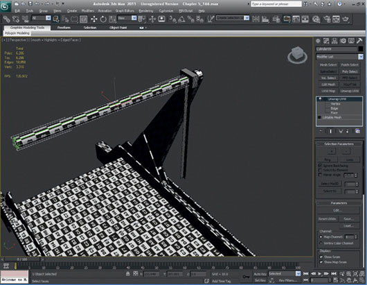
FIG 5.154
Now, we can mirror the objects like we have done with the previous models. Once you have mirrored the models and sorted the unwrapped faces, attach the models together to make one whole model—be sure to include the trailer.
Next, hide the trailer and unhide the stabilizers. We will map these in the same way as the trailer arms. Once you’ve finished, they should look something like Fig. 5.156.
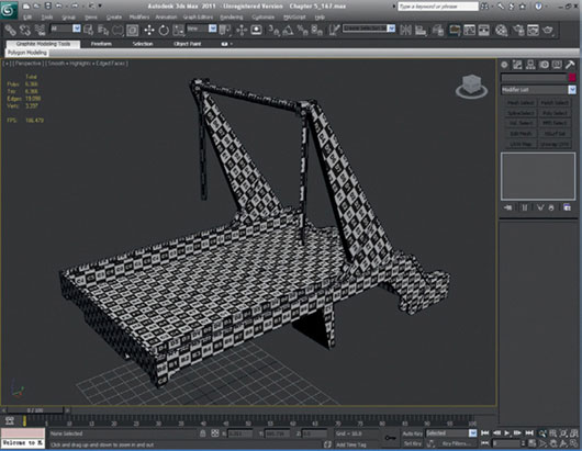
FIG 5.155
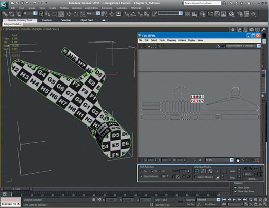
FIG 5.156
Mirror the stabilizer and attach it to the rest of the trailer. Your unwrapped trailer should look something like Fig. 5.157.
Let’s start unwrapping the wheels. Unhide and unfreeze the chassis layer (or layer 04 if you have not named your layers). We have only one front and one back to do, as they will obviously be mirrored. Apply cylindrical mapping to the wheel in the UVW Unwrap window (if one wasn’t assigned on creation).
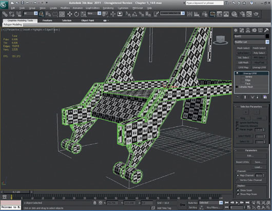
FIG 5.157
Move the outer polygons away from the central hub and map the hub and side wall of the wheel with a planar map. The inner hub cylinder should be cylindrically mapped, just like the outer faces of the wheel. The outer polygons will be mapped with a tread texture; this will be the same on all of the wheels, so the faces should occupy the same UV space on the texture page. In fact, only the hub front and back faces are unique on the front and rear wheels. After you have finished, you should have something that looks like Fig. 5.158.
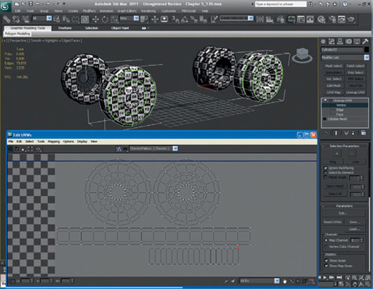
FIG 5.158
Now, we can follow the wheels with the rest of the chassis UV mapping. Again, you should see that there are some parts of the model that can occupy the same UV space, such as the main chassis girders, brake drums, leaf springs, and leaf spring brackets. When you have unwrapped all of the chassis, attach together all of the pieces, just as we did for the trailer.
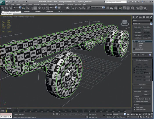
FIG 5.159
Unhide and unfreeze the cab layer again, as we just need to unwrap the engine block, prop shaft, seats, and steering wheel and column. Now, it’s time to attach the entire truck model.
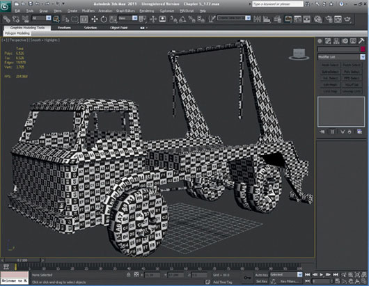
FIG 5.160
Now comes a tricky part. Once you have the entire model unwrapped, it needs to fit into a square. What I mean by a square is a texture page that is basically of a resolution to the power of 2. In this case, we are going to make the entire unwrapped model fit in a texture page with a resolution of 1024 × 1024 pixels. You might want to create the texture slightly larger—2048 × 2048, for example—so that you have a higher resolution map for renders or your portfolio. When you are finally organizing your texture page, keep in mind the priority of the model. For example, I suggest that you make the interior, the underside parts, and the objects that are obscured or seldom seen a little bit smaller on the texture page. This method allows you to assign more of the texture page to the most visible parts of the truck.
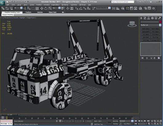
FIG 5.161
It is time to experiment and see what you consider to be the best compromise. Once you have all of the faces into the square, you can either take a screenshot and paste that into Photoshop or in the UVW Unwrap Editor under Tools or use the Render UVW template. Make sure that the resolution is set to 2048 × 2048 for the original map.
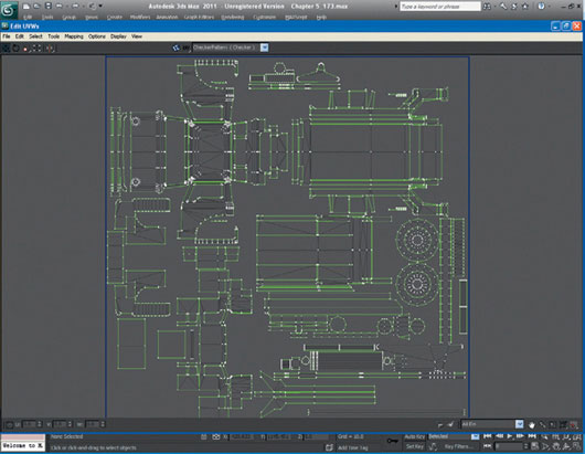
FIG 5.162
Creating the Texture Map for the Truck
Open the texture template in Adobe Photoshop. I suggest that you use the layer functions in Photoshop and even the layer folders to keep the collection of your textures together. What we need first is base rust texture template. To get that, I am going to use what images I can find in the reference photos and seamlessly stitch them together using the Clone Stamp and Healing Brush tools.

FIG 5.163
Grab as many of the truck parts as you can from the reference images and line them up with our model UVs. Don’t worry if they look a bit odd and the perspective is a bit off; you will probably need to do a lot of editing to line everything up and make them seamless. Tidy up parts of the textures as you go, just to make things clear on the page. Actions like trimming the images as you are placing them into the file will make your blending job that much easier when it needs to be done.
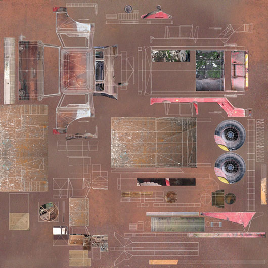
FIG 5.164
Use Photoshop to blend, copy, clone, color-correct, and generally fix all the photograph parts of the truck for the parts of the images that we have copied into our texture file. Feel free to use the other photographs or references for the tire tread and front wheels. If you find that there is a reference missing or if you don’t think that there is enough information in some of the texture parts, use an Internet image search to complete your texture map.
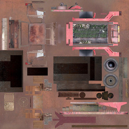
FIG 5.165
You should now have something that looks like Fig. 5.166 when you have finished the texture corrections:
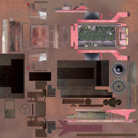
FIG 5.166
The only remaining tasks are creating the alphas for the seat, steering wheel, and chain by making an opacity map in Photoshop. Keep the original alpha in channels within Photoshop or create a new layer set and keep a layer as an alpha, but save a copy of your alpha map as a JPEG to be used in 3ds Max. If you intend to do any close-up render shots of the truck, you might want to create a higher resolution chain texture on your main texture page. This process is easy—and you should have plenty of space on your texture page.
FIG 5.167
In 3d Max, apply the texture map to the truck.
Congratulations! You should now have a fully modeled and textured truck.
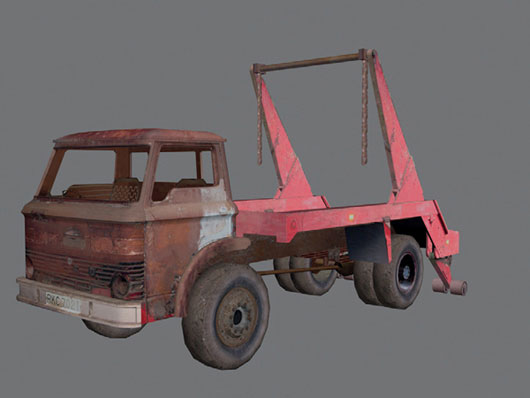
FIG 5.168