
Normal maps have become a commonly used technique that has helped define the look of the current generation of video games. The purpose of a normal map is to make a low poly model look like a high poly model.
Usually, this means two different models need to be created to “transfer” the information from the high-resolution mesh to the low-resolution mesh.
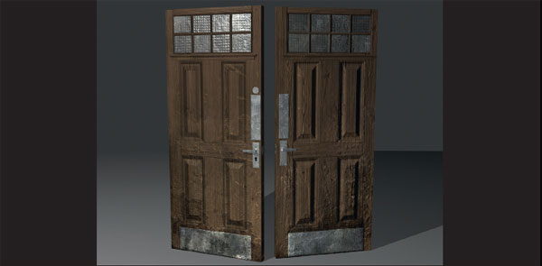
Below are examples of a tangent space normal map baked from a high poly model and applied to a low poly version.
Each surface on a model has a normal direction. The surface normal is like a perpendicular line protruding outwards from the surface of the polygon. Normal maps work by storing a model’s surface normal direction information in the RGB channels of a texture. Figure 7.2 shows some surface normals of a sphere.
The red and green channels of a normal map use a range of gray scale values ranging from black to white to represent the normal direction along the X- and Y-axes. The Z-axis represents depth; in a tangent space normal map the blue channel can only be a positive value, so the gray scale values range from 50% gray to white. The following image shows the three RGB channels first separately and then combined.

FIG 7.1

FIG 7.2
When a normal map is applied to a model with the correct shader, the information stored in the RGB channel is used to describe the normal direction of each pixel on an object’s surface. These details react to lighting in real time as if they are actually modeled into the surface. The amount and crispness of details from the high-resolution model that will be captured by the normal map is limited by the texture’s resolution.
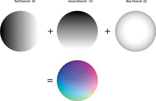
FIG 7.3
There are three main types of normal maps. Figure 7.4 shows a normal mapped head model. The example on the left is a tangent space normal map, and the one on the right is an object space normal map.

FIG 7.4
World Space and Object Space Normal Maps
These normal maps are visually different from tangent space normal maps as they use a wider spectrum of colours to define the different values for the normal direction of each pixel in relation to world space co-ordinates used in a 3D program. From a performance standpoint, world space normal maps are the most efficient. Object space normal maps are second. These techniques do come with certain limitations though.
One limitation of world space and object space normal mapping is that they must have their own distinct UV coordinates. Therefore, you can’t reuse parts of the texture for more than one part of the model.
Models assigned world space normal maps cannot be rotated from their original position that they were created from, and the vertices of the model cannot be deformed as this will result in the surface normals’ directional values being incorrect for their position and the surface being lit wrong.
Object space normal maps can be moved but cannot be deformed. Consider these restrictions when deciding which method to use. World space normal maps are best for unique static objects that will not move, such as a building. Object space normal maps are good for objects that move but do not deform—for example a door, window, or barrel.
Tangent space normal maps are easily recognized by their mostly blue appearance. Tangent space normals almost always look bluish because normals in tangent space are always considered “up” (coordinates 0, 0, 1), even if in world space this is not true. The normals mapped on this triangle are thus encoded, and that’s the key point, relatively to (0, 0, 1). Because most normals are pointing “up,” and since the vector (0, 0, 1) is colorized as blue-purple-ish, the result is a blue-purple-ish normal map. The benefits of tangent space maps are the removal of the restrictions imposed by world space and object space normal maps. Tangent space normal maps can rotate and deform; therefore, they are ideal for characters or objects that need to have vertex deformation, such as water or tree limbs.
In dealing with 3ds Max, the red channel is lit from the right, the green from below, and the blue represents depth.
The Process of Creating a Normal Map
Now that we have a better understanding of what a normal map is, let’s go through the steps of baking a normal map from a high poly model in 3ds Max. You can use any model you wish to as long as you have a high poly model and a low poly version with UV coordinates before starting.
For this example, I have chosen to create a door. The high poly was modeled using the standard tools. A lot of the geometry is floating or intersecting geometry. When it comes to creating high-resolution models for generating normal maps, there is less need to worry about the amount of polygons or how clean the mesh is.
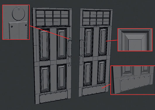
FIG 7.5
When creating high poly models for generating normal maps, try to avoid creating faces parallel to the surface normals. These details do not come out well because of how a 3D program gathers this information. It’s better to chamfer edges or at least scale in any faces to ensure there are no faces at 90° angles to each other.
Figure 7.6 shows two diagrams to explain this. The one on the left shows a low poly surface in blue and a high poly shape with a raised cube on the surface. When a 3D program is baking, texture “rays” are cast perpendicular to the low poly surface in the direction of the surface normal. When these rays hit the high poly mesh, it gathers the information.
In the left image, as the sides of the extrusion are perpendicular to the low poly surface, this results in the surface normal direction appearing totally flat as the rays don’t pick up a face parallel to them.
The example on the right has two corner edges chamfered or beveled. This creates new faces with a surface normal direction different to the low poly surface. As the rays hit these new faces, the data is converted to values in the RGB channels of the normal map.

FIG 7.6
A simple way to check models before you bake the maps is to use one of the orthographic viewports such as the front or left ones to view the high poly model. If you can see all the intended details clearly, the normal map should turn out similar.
Figure 7.7 shows this quick test. The horizontal chamfered box appears clearly in the normal map and screen grab of the front viewport, whereas the vertical box with sides perpendicular to the surface of the low poly mesh appears nonexistent in all images.

FIG 7.7
Since all we need is the surface normal information of this model, we can just create planes of the same size to bake the information on to before applying the final normal map to a fully modeled door. If you already have an existing low poly model, you can use that.

FIG 7.8
I have also created two different sides for the door to show the locking mechanism for both doors. Simple planes of a relative size have also been created for these in preparation to bake the normal map.
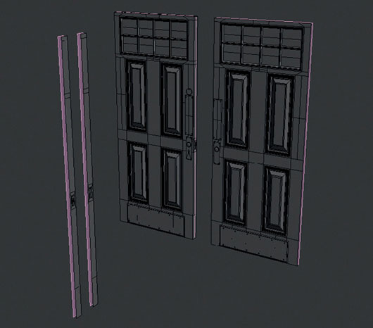
FIG 7.9
All meshes have been spaced out, so when the rays are cast from the low poly surfaces, they won’t pick up any of the other meshes in the scene. Attach all the low poly planes together, so they can be unwrapped to one texture sheet. These planes need to have UV coordinates, so apply an Unwrap UVW modifier and planar map the low poly meshes. The UV layout is displayed in Fig. 7.10.

FIG 7.10
The final scene setup was displayed in Fig. 7.9. This file can be found in the chapter files here if you wish to jump straight into baking a normal map. Chapter7CH007_assets door_scene_for_baking
We are now ready to bake the normal map. I’ll be baking a tangent space normal map as I wish to reuse the texture on the front and back of the door. This is not possible with object or world space normal maps as they require unique UV space for every polygon.
Select the low poly mesh and press 0 to bring up the Render To Texture dialog or go to the main menu > Rendering > Render To Texture.
Select the low poly model as this will need to be selected from the beginning. It will appear in the list in the “objects to bake” section.
First up are the general settings; we will change the render settings. Open the drop down list and select the top option. Default scanline renderer. You can also chose the output path of where to save the files from the general settings also.

FIG 7.11
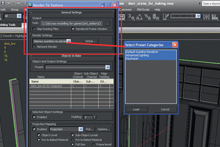
FIG 7.12
Under Projection Mapping in Objects to Bake, select Pick; a new window Add Targets will pop up. Choose the high poly mesh by its name, in this case door_high. You may have noticed a new modifier called Projection has appeared in the low poly models modifier stack. We’ll be using this soon.

FIG 7.13
Now click on Options beside the Pick button to bring up a new window titled Projection Options.
The default settings should be ok, but just make sure the following is selected.
Method > Raytrace > Use Cage
Resolve Hit is at Furthest and that Ray miss is checked.
Normal Map Space is set to Tangent. The orientation is Right, Green.
If you wish to bake a world space normal map or an object space one, you could choose the World or Local XYZ options instead of Tangent.
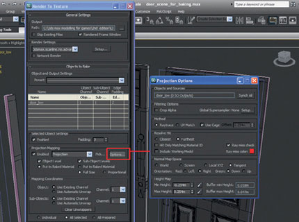
FIG 7.14
Under Mapping Coordinates, select Use Existing Channel as the object has been unwrapped.

FIG 7.15
Add a normal map to the Output section by clicking Add and choosing NormalsMap from the list.
The Selected Elements Common Settings will appear. This is where we name the output texture and input its location to save it by selecting the icon to the right of file name and browsing to the desired location. You can also pick the texture’s size by selecting from the options. I’ll go for a 1024 × 1024 this time. It’s useful to bake the maps at a smaller size than needed at first to iron out any problems that come up before committing a long time baking a really large map.

FIG 7.16
Going to the projection modifier and selecting the cage mode adjust the Cage to ensure it is covering the high poly mesh closely and that no areas are overlapping. The cage is represented as a blue wireframe.
This can be done manually just like editing a mesh. It may be easier to Reset the cage and adjust the Push values if the automatic cage has exploded too much. These settings are found in the modify panel. Figure 7.17 highlights these.

FIG 7.17
These are the only settings we’ll need to deal with to get a tangent space normal map baked out. Once you are happy that the cage is sitting away from the high poly model, it’s time to render the texture.
Go to the bottom and press Render; this will then bake the map for you and save it in the specified location as the chosen file type. A warning window will appear as we have not specified a target map slot in a shader. This is ok to ignore; press Continue.
The texture will render as a gray scale map. Open the Output file or reload it into the scene to see it as a tangent space normal map.
Now that we have a normal map, it needs to be applied to the model. I created a simple door double model with fronts and backs. The total triangle count was 542. This also included four handles and a modeled rim to sit below the glass panels.

FIG 7.18
As a normal map does not affect the silhouette of a model, I left these few elements as geometry to add depth to the model. The rest of the details such as the recessed panels and keyholes were left up to the normal map. Figure 7.19 shows the tangent space normal map baked from the high poly and the unwrapped low poly model.

FIG 7.19
To apply the normal map to a model press M to bring up the material editor.
Select a shader to use. Under the maps list, tick the box to the left of the bump slot to activate it.
Increase the value from 30 to 100. Now click on the button None to the right and select normal bump from the list.
Click on the new None button that appears beside Normal: and select bitmap from the list.
Browse to the location of the output tangent map and select it. The map will now be loaded.
Press Go to Parent twice to go back to the main material editor screen.
Now left click and drag from the shader image to the mesh you want to assign the texture to. If the normal map does not appear in the view port go to the main menu > views > Show Materials in Viewport as > Hardware Display with Maps to display the normal map in the view port.
Figure 7.20 shows the high poly model on the left, the low poly model in the centre, and then the low poly model with the normal map applied to the right.

FIG 7.20
The door as it is now is looking reasonable, but it is missing the finer details such as wood grain to really push it further. It is possible to create these details in a sculpting package such as Z-Brush or Mudbox, but it’s quicker to create these details in Photoshop from a modified gray scale version of the diffuse map.
Figure 7.21 shows the diffuse, specular, and normal maps that combine to give the final look to the doors surface. To create the specular map, the diffuse texture PSD was copied and renamed to be the specular PSD. All layers were desaturated and then had their levels adjusted to create contrast in the doors materials. Metal and glass elements were lightened to be shiny, and the wooden surfaces were darkened so they’d almost be a matte surface.

FIG 7.21
Figure 7.22 shows the original normal map created in 3ds Max on the left and the final normal map on the right that had the finer details added in Photoshop. These new details were created by duplicating the diffuse texture PSD and desaturating all the layers similar to the creation of the specular PSD.
I then went through the layers adjusting the levels until I was satisfied. Figure 7.23 shows the two different sets of details I was working on. The wood grain is on the right and was kept separate, so I could control how strong it would be in the final normal map.
The rest of the details such as dirt build up and damage can be seen on the left. When creating gray scale images to be converted into a normal map, remember that lighter values will be raised from the surface and darker values will recede into the surface.
When I was happy with the two images, I ran them through the nvidia normal map plugin available to download for Photoshop. These new layers were then placed over the original normal map from 3ds Max and set to overlay. The opacity was adjusted until all the details sat well together.
When the image was ready, I flattened the texture and normalized the normal map using the nvidia plugin. This is important as the values in a normal map can only range from 0 to 1, black to white. By normalizing the normal map, it adjusts any values outside of this range.

FIG 7.22
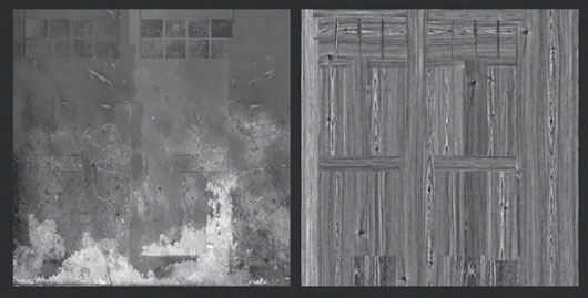
FIG 7.23
Figure 7.24 is a render of the low poly door with all the final textures applied to the model.
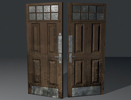
FIG 7.24
• Normal maps create more work for the artist. Always consider whether you actually need one.
• A tangent space normal map is the type most commonly used in games.
• Spending time in preparing a UV layout saves you time in the long run.
• Do not flip UVs; doing so will make your normal map display incorrectly.
• Building individual details and combining them in image manipulation software is a quick way of developing complex detail, without long build and render times.
• Normal-mapped elements can be moved and scaled but not rotated in image manipulation software.
• Avoid sharp angles, which can create strange artifacts in the normal map. This also applies to hard edges from smoothing groups. Unless you want a hard-edged look to your final model with the normal map applied, ensure the low poly model has all the smoothing groups set to 1 before you bake a normal map as hard edges may result in missed details and artifacts in the final texture.
• The quality of the normal map is dependent on its resolution and compression.
• Normal maps cannot be edited like normal textures. If you do need to edit one, make sure you use a plug-in to “normalize” the normal map when you are finished, so the values sit back within the 0–1 range.
• Normal maps can display differently depending on the software and hardware used. If you notice your normal map not lighting correctly, invert the green channel as this is usually the cause.
• It’s best not to create any lighting information in the diffuse texture when using normal maps as they will take care of how the surface is lit.