
4. Working with EDPs
Until now we’ve talked about Elemental Design Patterns (EDPs) using a number of metaphors, including building blocks, and comparisons to the periodic table of chemistry. Those metaphors and comparisons were selected because they are used in domains where composition of fundamental pieces into larger, more useful constructs is critical. This applies for us as well and leads to an assumption that EDPs can be joined into meaningful larger pieces. In Chapter 3, you were introduced to Pattern Instance Notation (PIN), and part of that discussion showed how PINboxes can be joined in a diagram, illustrating how multiple instances of design patterns such as EDPs can interact.
In this chapter, we put all of this information together and demonstrate that EDPs are not just small individual concepts. EDPs form the basis for much larger abstractions and design patterns and can be used effectively in a multitude of situations, including designing, implementing, and rewriting a system.
4.1. Composition of Patterns
Let’s revisit our discussion and deconstruction of Decorator in Chapter 2, Section 2.2.1. We identified that Object Recursion was being used and that Objectifier was a part of Object Recursion. The deconstruction process required deep knowledge of the existing design patterns literature, yet the end result was vague and did not give us a comprehensive understanding of Decorator. We’ll use EDPs to give a more complete picture.
Let’s start with one of the basic object-oriented programming EDPs we just described, Abstract Interface. We stated that it promises that a future subclass will provide an implementation for the specified method. Let’s go ahead and mock up the pieces of this pattern with UML. We know we have Abstract Interface, and we know we need Inheritance because we talk about a subclass. We can show these as in Figure 4.1.
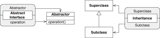
Figure 4.1. Abstract Interface and Inheritance EDPs as UML.
Now let’s connect these two EDPs in a very specific way. We know that Abstract Interface talks about an “unspecified subclass” of the Abstractor class, suggesting that the class fulfilling the Abstractor role is a superclass. Let’s show that by having the Superclass role in Inheritance point also to the Abstractor class. This merges the two UML diagrams into one, as in Figure 4.2. We applied what we first saw in Chapter 3, Section 3.2.2, connecting the two EDP instances, and created a larger design. We added one more piece of information to this diagram: the Subclass role of Inheritance provides the concrete definition of the operator role from Abstract Interface. This is new and appears in neither EDP.
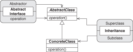
Figure 4.2. Internal definition of Fulfill Method as UML.
This new definition fulfills the contract that is the conceptual essence of Abstract Interface, that a subclass would provide an implementation for the abstract method, and gives rise to the name for this new design pattern: Fulfill Method. This is a concept you haven’t seen yet in this book, although I’m sure you’ve seen it if you’ve ever programmed in an object-oriented language. We alluded to the composition of patterns at the end of Section 3.2.2, and showed this in Figure 3.12, but it wasn’t fleshed out. Let’s do that now.
Let’s redraw Figure 4.2 but without the UML, as we talked about in our PIN discussion. In Figure 4.3, the implementation details are removed, and the figure shows only the relationship between the two EDPs. It cleanly abstracts out the relationships that are contained within each EDP. A simple diagram remains, showing more clearly what the connection is between these two concepts. We can then wrap this new simplified diagram with the Fulfill Method PINbox, as in Figure 4.4.
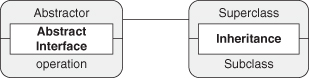
Figure 4.3. Fulfill Method as simple connected PINboxes.
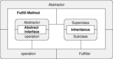
Figure 4.4. Fulfill Method as expanded PINbox.
The real payoff for this style of notation is illustrated in Figure 4.5, when we collapse the expanded PINbox and move to a higher level of abstraction. This is equivalent to each of the preceding figures but is a simple, single PINbox that can be used to annotate a UML diagram or, as we’ll see later, as a part of yet larger design pattern definitions. This almost fractal nature of PINboxes and design patterns will come up over and over again in working with patterns. Design patterns are made of smaller patterns, with the smallest, indivisible patterns described by the EDPs. In turn, all design patterns, starting with the EDPs, are usable as building blocks for larger patterns. At every level of granularity, PINboxes can be used to concisely depict the concepts under consideration.
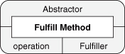
Figure 4.5. Fulfill Method as standard PINbox.
If you were following closely, you may have noticed that along the way we dropped one piece of information. When originally describing Figure 4.2, I stated that “we add one more piece of information to this diagram: the Subclass role of Inheritance provides the concrete definition of the operator role from Abstract Interface. This is new and appears in neither EDP.” The concrete definition of the operation, however—the entire defining feature of Fulfill Method—was not carried forward from Figure 4.2 to Figure 4.3.
This highlights two important points that you must keep in mind when studying patterns and using PIN. First, PIN is not a notation for the formal description of patterns. It is not designed to define every tiny feature of a pattern. It is designed to let you work with pattern instances quickly and easily and, where possible, assist in the depiction of pattern definitions. If you are looking for a mathematically precise formalization of design patterns, I can only point you once again to the appendix as a starting point. PIN is an approximation of that formalism, intended for human consumption.
Second, and much more important, you must never forget that when it comes to any design pattern, it is the write-up or pattern specification—the prose description of a design pattern—that is the essence and heart of the pattern. Mathematical notations can describe what a pattern looks like, they can list and name the pieces and how they are hooked together, but they can never tell you the most critical thing about patterns. They cannot tell you the why. They cannot tell you the when or where. At best, they can tell you the what. What is good, but what is not wisdom. Wisdom, the knowledge that patterns are intended to impart, is everything else surrounding the what. If at any time you are confused about a pattern, about how it is being applied, about its applicability or its critical concepts, consult the canonical document for that pattern. Refer to the specification. In your studies and application of patterns, notations such as PIN or even formal calculi will never be a complete substitute for the write-up, only a mnemonic assistance.
The preceding example may not seem like much, but it’s a critical step in understanding EDPs and how they form larger patterns. We took two EDPs, each of which define one relationship between two entities, and stitched them together to form a slightly larger pattern. What you just saw is the essential action of good design—taking small, understandable pieces that are appropriate to the problem at hand and putting them together in meaningful ways. What’s more, there is no end to this process. Every time we add a new relationship to a program, we alter the design in some way. The trick is recognizing which alterations are helpful and which ones lead to trouble.
In such a small case as constructing Fulfill Method, this may seem painfully obvious. “Well of course,” you might say, “how else would you put those two EDPs together?” Well, we could try to connect them as in Figure 4.6. These are the same two EDPs, but we reversed which class is the subclass. Now we can’t add that method definition like we wanted to!1 To make this easier to see, let’s redraw this connection with just the PINboxes, as in Figure 4.7. This is simply not the same graph as Figure 4.3.
1. This isn’t strictly true: some languages do allow for such removal of methods via later abstraction, but we won’t get into them here because that’s an advanced theoretical trick well beyond the scope of this book. Besides, such a removal would be a very different concept, wouldn’t it? We wouldn’t be fulfilling a prior promised method implementation, we’d be erasing access to prior method implementations.
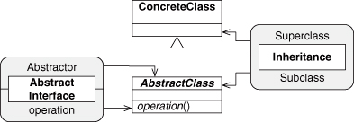
Figure 4.6. Flipping our EDPs in Fulfill Method—oops.
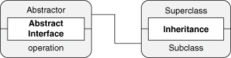
Figure 4.7. Flipped EDPs as PINboxes.
Only one specific combination of concepts will get us to where we wish to be. This is the magic behind design patterns: through trial and error, we can find the best-practice solutions to problems we keep running into. We can write down these solutions as a combination of smaller concepts that can be reused and sculpted into new forms while retaining the wisdom of the original conceptual connections. EDPs allow us to build our best-practice solutions out of primary blocks instead of through trial and error.
Another point to be made is that Figure 4.2 shows the absolute minimum UML that satisfies the EDPs in the PINboxes, not the exact solution. This is not the implementation; this is one implementation. Recall that we’re giving ourselves a way of talking about design issues such as patterns without limiting ourselves to a highly specific and rigidly defined implementation. We can return to the individual EDPs that comprise Fulfill Method and look at how they can differ in their implementations yet still be the EDPs we wish them to be.
4.1.1. Isotopes
Any given design pattern, whether one as small as an EDP or as large as a full-blown pattern such as Decorator, can be implemented in a vast number of ways and still embody the concept being described. This flexibility is a hallmark strength of design patterns. We call these differing implementations isotopes of the pattern. The name is intended to be congruent with the term elemental. In chemistry, an isotope is a variation of an atom of a particular element. Atoms have three components: electrons, protons, and neutrons. The protons and neutrons form the nucleus of the atom, and the electrons orbit the nucleus. The number of protons in the nucleus determine what element the atom is, and the electrons determine how that atom connects and interacts with other atoms. An isotope of an element has the same proton count as other atoms of that element, and it has the same electron shell structure. Because of these two traits, it behaves chemically the same as other isotopes of that element. It connects to other atoms in the same way, forms the same bonds, and for most intents and purposes can be considered the same as any other isotopic atom of that element.
Internally, however, an atom of an isotope has a different number of neutrons in the nucleus. From the outside, it looks and acts the same chemically, but the internal differences can cause small, insignificant side effects, like, oh, nuclear fission. This tends to be rather disruptive.
In software, we call this unexpected nuclear fission a crash.
An isotope of a design pattern in software is defined similarly. It is an implementation of a design pattern in which the core concepts of the pattern—what define that design pattern to be different from all other design patterns—and the external interface remain the same.
In other words, the roles that must be fulfilled do not differ from the expected design pattern description.2 This is analogous to the electron shells in the atom metaphor and is made explicit in the PINbox notation. All that an external entity, such as another pattern instance or code element, will see are the roles surrounding the “nucleus” of the definition.
2. If the roles do differ, it indicates a fundamental change to the design pattern. This change is called a variant of the pattern and is a clue that something very substantial has changed, such as the problem being solved or the context in which it is occurring.
The proton count in an atom is what distinguishes it from all other elements and places it in a specific position in the periodic table. We have a similar situation with design patterns, where the problem, solution, and context are unique. What the design pattern does, what it solves, and so on, is its discriminator. It is what makes it unique from all other design patterns. Change the problem, and we have a different design pattern. Change the context and, again, the design pattern must adapt and change into something else. If it’s a small change, and the resulting new pattern looks a lot like the original, then we have a variant; if it’s a large change, then we may have something wholly new.
With EDPs, the analogy to atoms and the periodic table is even stronger, because the axes of design context defined in Section 2.2.4 create a well-defined space within which we can uniquely place each EDP. This is directly comparable to chemistry’s periodic table, which creates a well-defined space in which the elements can be placed and the properties of those elements can be predicted.
The position of an EDP within the method-reliance EDP design space—as defined by the object-, type-, and method-similarity axes in Section 2.2.4—is absolute. Alter the value of any one of these three axes and the position within that space changes. The original EDP has mutated to another one, and you can predict what the properties of the new EDP will be. Change anything else about the EDP, however, such as how it is expressed in a particular instance, and the EDP stays the same while the implementation shifts—different implementation but the same properties.
With an isotope, either chemical or in design patterns, what differs is the internal structure. In the atom, it is the neutron count that changes. In the instance of a design pattern, it is the how that instance was implemented. These can have farranging effects, even if they are not immediately identifiable from the outside. At any moment, an unstable atom can split depending on its neutron count, and at any moment, a poorly implemented instance of a design pattern may cause a crash, even though from the outside it looks fine.
The idea of separating the implementation from the external interface is not new to object-oriented programming, it is quite natural and embedded. The new concept introduced in isotopes is separating the implementation and interface of a concept in the same manner. Remember that each design pattern has a series of roles—noted in the participants section—that must be fulfilled by portions of an implementation. These roles are the external interface through which the design pattern interacts with other concepts and patterns.
The collaborations section describes how these roles interact internally at the conceptual level, but these interactions can be described and discussed independently of the implementation. This is where the formalisms from the appendix come into play and provide a tremendous amount of flexibility, but the concept can be shown here with a code example. We hinted at this back in Section 2.2.2 with a simple example of transitivity between methods, but now we can go into it in more detail.
Start with the left side of the following code examples, where an object f has a method foo calling method bar of object b. We say that f.foo relies on b.bar. The object, type, and method similarities between those two endpoints is well defined and specifies the EDP between them. If the implementation is changed, for instance, by injecting a new object in a method-calling chain, the construct is altered, but the relationship between the endpoints remains unchanged, as in the right-hand side of the code example. The original reliance is intact, and the three similarities remain intact. New reliances have surely been created, but the original ones necessary for the design pattern remain. The new implementation is an isotope of the original EDP: it looks the same and acts the same when viewed as a concept from the outside, even if it looks different internally.
More important, it allows developers to talk about the design of the system without having to be concerned with every tiny implementation detail. We can discuss the design at a higher level of abstraction.
As an example, let’s revisit the construction of Fulfill Method and see how isotopes can help provide flexibility with even this small example. At the end of that construction, I mentioned that the UML shown in Figure 4.2 was the minimal UML required, not an exact requirement. Had we defined Fulfill Method using that exact UML, then any alteration to how we implemented Fulfill Method would require a new definition for the pattern. Because the number of ways that Fulfill Method could appear in a system are many, this would lead to a large number of definitions for such a simple concept. This is suboptimal.
The class that fulfills the Abstractor role in Abstract Interface can have any number of other fields and methods associated with it. It just has to have at least one method that is abstract. Figure 4.8 shows multiple UML classes, any one of which can have an Abstract Interface instance associated with it. Any one of these can be used to show the existence of an instance of Abstract Interface. It doesn’t matter how many attributes or fields a class has, how many other methods it may have, or whether it’s a template or generic class. The class simply has to have one method that is abstract.
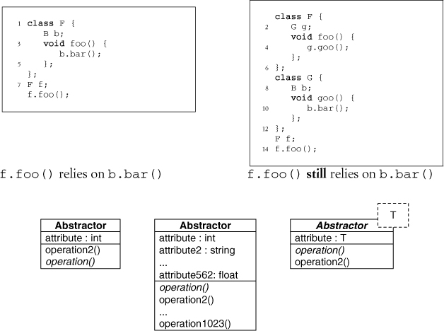
Figure 4.8. Alternative classes that can fulfill an Abstract Interface EDP.
Stated differently, the instance of Abstract Interface shown as a PINbox in the diagram for Fulfill Method in Figure 4.4 can stand in for any of these or for a nearly infinite number of other implementation possibilities. By using just the PINboxes, we don’t have to deal with all the possible UML representations or code implementations.
Likewise, the two-class, minimalist version of Inheritance we saw in Figure 4.2 isn’t the only way to satisfy that EDP. Any number of classes can be in the inheritance chain between the two classes we’re interested in, as shown in Figure 4.9. The depth of the inheritance tree doesn’t matter because a subclass is still a subclass.3 Again, the instance of Inheritance depicted by the PINbox in Figure 4.4 is representative of any of these possible implementations.
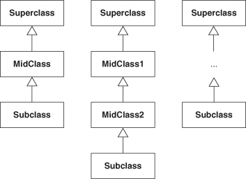
Figure 4.9. Alternative structures that can fulfill an Inheritance EDP.
3. This is another example of transitivity, and it is a core feature of the ρ-calculus described in the appendix, and what gives the EDPs their real power. See, I told you I was going to keep giving you nudges to go read the formal bits.
We can take this isotope concept even a bit further. Recall that not every language has explicit classes. This was a component of the discussion for using the term type in Section 2.2.2. How does subclassing work in such languages? We revisit that in the specification for Abstract Interface in Chapter 5, but even that kind of significant language-based change can be encapsulated by an isotope. We do not want to have to care what the implementation language may be, remember, and this is what lets us do that. By working at the level of EDPs and PINboxes, we remove ourselves from even the semantics of the language that may be used for implementation. Being language-agnostic is extremely powerful. What we’ve accomplished here, more or less, is polymorphism of design concepts.
With so many possible implementations for any given design pattern, you may be wondering how we know what the correct definition is for a design pattern. After all, I just showed you that for any given design concept, a huge number of possible implementations can exist. The patterns community still selects and writes down one canonical form for sharing, so what’s the criteria for selecting that one?
Simply put, what is transcribed is the simplest possible implementation and set of participants and collaborations. The final form provides nothing extraneous and gets to the essence of the concept being communicated. Anything beyond that simple core would obfuscate the central concepts and lesson. Isotopes almost always add additional items to the canonical description, yet in such a way that the concepts are still embodied.
Design patterns are created and edited in such a way as to get to the essence of the problem, the solution, and the context, to make teaching, learning, and using them as simple as possible. In the end, the simplest description is the best description. Let the isotopes handle the modifications of implementation.
4.2. Recreating Decorator
So far in this chapter, you’ve seen how very small concepts and design issues can be composed in well-formed and specific ways to form larger concepts. You’ve also seen how these concepts are an encapsulation of the implementation, so the design discussion can be simplified through abstraction. We’re going to combine these elements to build up a much more satisfying and robust definition of Decorator than we started with in Chapter 2.
We start by revisiting our initial UML diagram for Decorator in Figure 4.10 and our UML version of Fulfill Method in Figure 4.11.
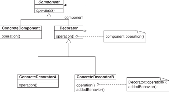
Figure 4.10. Decorator’s usual example UML.
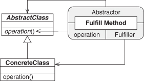
Figure 4.11. Fulfill Method definition as annotated UML.
Looking again at Decorator (Figure 4.10), we can see where the structure from Fulfill Method is found, in two places, with the Component class acting as the Abstractor role in both. On second thought, this is looking quite like our Objectifier pattern from Figure 2.2, isn’t it? Good eye. This is exactly what Objectifier is—the expansion of a single Fulfill Method across several concrete subclasses, as in Figure 4.12. Again, we’re using the PIN for Fulfill Method, shown here in its stacked form (see Section 3.2.4) to indicate how the underlying concepts fit together. We just defined a design pattern that already existed in the literature, but from first principles, by building it out of smaller, well-understood pieces. In Figures 4.2 through 4.5, we wrapped Fulfill Method in a PINbox. We do the same wrapping of Objectifier using Figure 4.12 as the internals but omitting the diagrams in between. This gives us a PINbox for Objectifier.
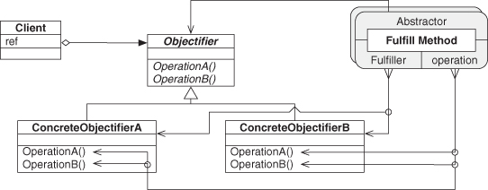
Figure 4.12. Objectifier UML annotated with PIN.
Taking this a step further, we can define Object Recursion as well. Recall that we said in Section 2.2.1 that Objectifier is a component of Object Recursion, but we did not address what the remaining part was. We can now identify it as the Trusted Redirection EDP. Figure 4.13 shows the two patterns as UML. In combining to form Object Recursion, FamilyHead and Objectifier will merge, as will ConcreteObjectifierB and Redirector.
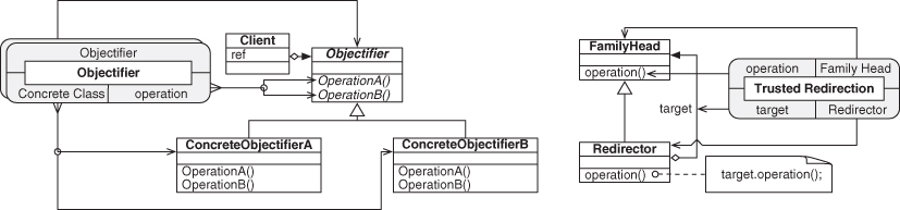
Figure 4.13. Objectifier and Trusted Redirection.
Figure 4.14 shows Object Recursion in a slightly cleaner form than as introduced in the original Figure 2.3, now annotated with the PINboxes for Objectifier and Trusted Redirection. The Objectifier role from the Objectifier pattern and the Family Head role from Trusted Redirection are now being fulfilled by the same entity, the class named Handler. Likewise, ConcreteObjectifierB and Redirector have merged into Recursor. This is shown more succinctly by the PIN diagram in Figure 4.15.
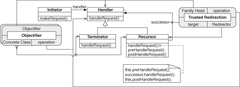
Figure 4.14. Object Recursion annotated with PIN.
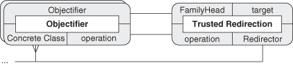
Figure 4.15. Object Recursion as just PIN.
We can now discuss Object Recursion in terms of smaller patterns and in a much more precise way than we could before. “Object Recursion uses polymorphism, through the Objectifier pattern, to determine at runtime which type in a related family of types will handle a specific call. By applying Trusted Redirection to at least one of the possible implementations, it also chains together two or more objects from that family such that they can handle that same call in turn and bring their own implementation to bear.” This statement is precise, it is direct, and it avoids having to discuss the pattern in structural terms. Furthermore, if someone is unclear on the underlying concepts, he or she can study the full pattern specifications of each of the subpatterns. We can leverage those specifications and definitions from the patterns literature to make our descriptions of higher-level abstractions and patterns much easier to comprehend.
We composed the top half of the Decorator pattern and have just one piece left to go to finish our definition. The remaining concept is Extend Method, which fills out the bottom of Decorator by extending Trusted Redirection, as shown in Figures 4.16 and 4.17. Extend Method’s original behavior and recursor from Object Recursion merge into Decorator, tying these two smaller patterns together.4
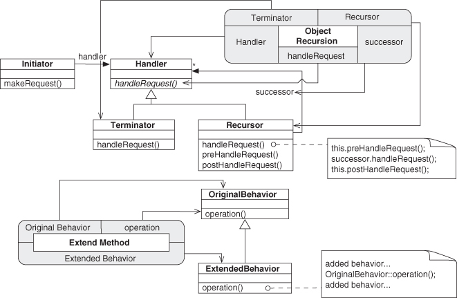
Figure 4.16. Object Recursion and Extend Method.
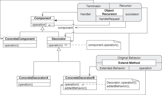
Figure 4.17. Decorator annotated with PIN.
4. ConcreteDecoratorA and Decorator form another leg of Inheritance, but we’re leaving it out for clarity at the moment.
We can simplify this by reducing it again to just the PINboxes, as in Figure 4.18. Furthermore, we can always wrap and reduce this to a single PINbox indicating an instance of Decorator, as in Figure 4.19. The role names here are taken directly from the participants section of the Decorator specification in the Gang of Four (GoF) text [21], with two additions: operation and componentObj. These are implicitly discussed in the participants section, but we make them explicit here to clarify the pieces involved.
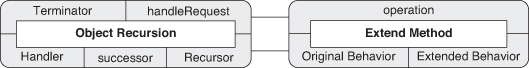
Figure 4.18. Decorator as PIN.
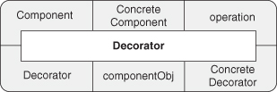
Figure 4.19. Decorator instance as a PINbox.
Now we have a simple, concise notation for the Decorator pattern. At this point, however, we can go the other way as well. We can use expanded PINboxes to increasingly expose finer granularity in Decorator by showing the underlying hierarchy of concepts. Figure 4.20 shows Decorator as an expanded PINbox, revealing its direct internal wiring. Figures 4.21 and 4.22 drill into Object Recursion and Objectifier, respectively, and finally Figure 4.23 expands Fulfill Method to the EDP level, at which point we can decompose no further. Decorator is now fully revealed. Each of these diagrams is equivalent to the others.
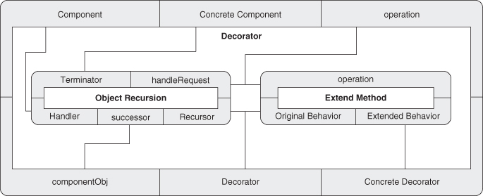
Figure 4.20. Expanding Decorator: one level.
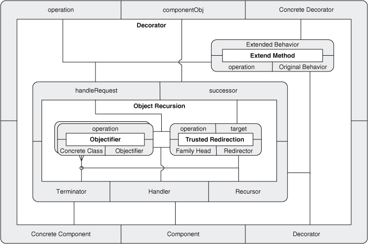
Figure 4.21. Expanding Decorator: two levels.
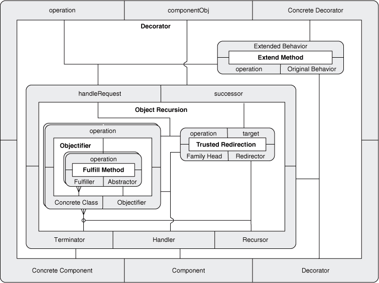
Figure 4.22. Expanding Decorator: three levels.
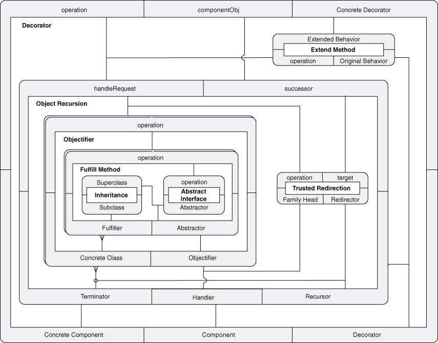
Figure 4.23. Expanding Decorator: four levels.
So that’s Decorator, and we built it with just four EDPs: Abstract Interface, Inheritance, Trusted Redirection, and Extend Method. Each is a simple concept, but together, linked in a very specific combination, they describe a fairly high-level abstraction that is commonly found in software systems. What’s more, we demonstrated that interim concepts can be studied and mastered to gain a more thorough understanding of Decorator.
Most important, we never once discussed code. We didn’t bring up classes, or methods, or fields. We talked about concepts and ideas only, yet we achieved a framework that provides guidance and precision.
In EDPs, we have the building blocks with which to form great software that we understand.
The final section of the GoF text [21, p. 358] uses a quote from Christopher Alexander to describe what is “good design.” I can think of no more fitting description of their own design patterns when viewed as dovetailed and intertwined examples of the EDPs.
It is possible to make buildings by stringing together patterns, in a rather loose way. A building made like this, is an assembly of patterns. Is it not dense. It is not profound. But it is also possible to put patterns together in such a way that many patterns overlap in the same physical space: the building is very dense; it has many meanings captured in a small space; and through this density, it becomes profound. [3, p. xli]
The design patterns literature is full of profundity through the composition of smaller concepts in dense and precise ways. EDPs let us view that density with clarity and insight.
One more comment. Do you recall the example from the beginning of Chapter 2 about the hidden Decorator pattern in industrial code that inspired SPQR? SPQR, using the EDPs, composition technique, and formalisms described here, was able to identify its existence in just a couple of seconds without being given any hints. Compared to almost 200 hours, that’s a lot of coffee breaks that could be taken instead.
4.3. Refactoring
In discussing isotopes in Section 4.1.1, I stated that a pattern isotope instance might look the same as another instance of that pattern from the outside but have a buggy implementation that causes problems later. Worse than a single poorly implemented design pattern, however, is having multiple interacting design patterns that all bring well-meaning and rational implementation choices to the system but form a problem when combined. Recall that the initial driving problem for SPQR, described in Section 2.1, was that a design pattern arose organically and unintentionally. Malignant designs can form just as easily, and because the number of ways to produce poor code is greater than the number of good designs, they tend to arise much more readily.
When it comes to design patterns, we can classify some of the “bad design” issues that can appear.
First are the anti-patterns, which you may have heard of [14]. These are patterns that should be avoided whenever possible. They express common poor practices, not best practices. If they exist in your system, you should work to remove them and find a proper design pattern to address the use case instead.
Next up are proper design patterns that are misapplied. Perhaps they simply weren’t implemented correctly and are missing critical pieces. Perhaps they weren’t understood by the designer or implementer and aren’t quite fully formed. These partial design patterns often are just one or two small tweaks away from expressing the original pattern.
Malignant patterns, on the other hand, are patterns that grew, but grew poorly. Where they may once have been applied and implemented correctly, code modifications over time have broken or mutated them into forms that no longer fulfill their original purpose. The worst side effect in this case is that documentation, if it exists, will frequently still refer to them and thereby mislead developers.
Finally, iatrogenic patterns are design patterns that were implemented correctly to solve an existing problem, as it was understood when the solution was selected. Unfortunately, larger design issues brought to bear forces and constraints that were ignored or unknown. The pattern solved the original problem but, by interacting with these other context forces, inadvertently created a new situation that may be worse than the original.
All of these problems can be solved by properly refactoring the code, which mainly requires moving functionality from one location to another to better streamline a design. The features and executable functionality of the system are not appreciably altered, but the ways the pieces hook together are. You’re not directly altering what the code is doing, but you may be enhancing what the code could do. By improving the design of the system, you’re improving the readability of the system, which means that it is easier for a developer to understand and modify the code. Adding new features, fixing bugs, and many other desirable actions are simpler and faster to undertake and complete.
Refactoring of code is well established in our field, and two sources in particular are worth pointing out. Martin Fowler’s Refactoring [19] and Joshua Kerievsky’s Refactoring to Patterns [24] form a dovetailed set of recipes for converting code from one configuration to another. Both are well worth your time to check out. If you’ve ever used an integrated development environment (IDE) such as Eclipse, Visual Studio, or Xcode, you have probably used refactorings via the capabilities provided in those tools. They automate the process of performing simple, useful tasks, and Refactoring was the starting point for much of this functionality. If you want a solid understanding of how best to use the automated tools, you can’t go wrong with these books.
Fowler’s text lays the groundwork for a catalog of small, discrete refactoring actions that you can take to improve your code design. For instance, he starts with “bad smells,” which are situations in which you know something is not quite right with the code even though it may perform correctly. He describes these gut feelings as possible indications of a subconscious uneasiness with the code design, with how understandable or cleanly expressed it is. The more experience you have with programming and the more exposure to good design principles, the more you’ll learn to trust your instincts in these cases.
For each bad smell, Fowler provides a series of actions to alleviate the problem. These actions are wide ranging and varied, but I focus on only three here.
Extract Method, for example, is a refactoring action that can be used to solve a smell involving a method that’s too darned long and difficult to understand. In its simplest form, it directs you to extract a self-contained portion of the long method into its own method and call it. Great significance is given to the naming of the new method, which shouldn’t surprise you by this point.
This significance is exemplified in Rename Method, used to clarify intent when a method’s usefulness or applicability may be obfuscated.
Similarly, Move Method is used to clarify which methods belong together. Clarification is needed when, as Fowler states, “a method is, or will be, using or used by more features of another class than the class on which it is defined.” In other words, use Move Method when, for some reason, the method is in the wrong class.
Now, these may seem trivial, but each one has implementation subtleties that make Fowler’s contribution necessary and rightfully a classic in our field. More to the point, Fowler uses these tiny, well-formed actions as building blocks for larger refactorings that are more complex. Kerievsky takes this concept and runs with it, using Fowler’s catalog as the seed for even richer refactorings that show how to methodically and precisely migrate toward implementations of the more common design patterns. Sound familiar?
An interesting parallel is at work here. We can continue it by considering the Extract Method refactoring. The effect of this refactoring is to create a new method and a new call to that method. The method that the chunk of code is extracted from is the calling site, and the new method is the callee. Obviously, the two methods can’t be the same,5 so we assume at this point that the methods are dissimilar. Also, because the new method is being formed in the same class/type—according to the refactoring definition—we have the same type and also the same object. Well, we know what this is from our discussion in Section 2.2.4. The EDP with the same object, same type, but dissimilar method is Conglomeration.
5. Once again, we’re ignoring overloading for now. Assume that similarity is based not only on the name but on the entire method signature.
Next, let’s ponder Rename Method and what it might mean for an EDP that the renamed method is involved in. Remember, method similarity is (partially) determined by the name of the method. If we alter the name, we could be moving from a method-similar EDP to its method-dissimilar equivalent. For example, consider an instance of Delegation, as in Figure 4.24. If the target method called() is renamed to caller(), it now is similar to the calling site, and Delegation has become Redirection, as in Figure 4.25. Of course, the rename could be to anything, and this EDP transformation only holds if the new name is a similarity match. So now we can say that Delegation + Rename Method (to similarity) = Redirection. Going the other way, Redirection + Rename Method = Delegation.
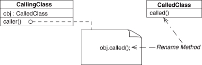
Figure 4.24. Delegation before Rename Method refactoring.
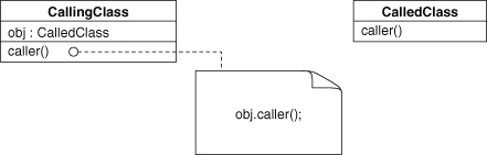
Figure 4.25. Delegation after Rename Method refactoring—Redirection.
With each change in the design, no matter how small, we alter the EDPs that are components of it. The EDPs will in turn affect the design patterns that are formed from them, and so on up the compositional hierarchy. By knowing precisely how alterations such as those enumerated in the refactoring literature will affect our design on multiple levels of granularity, and by knowing precisely how those refactorings will percolate changes throughout our system, we can better predict what the larger ramifications of a planned design change will be.
Large changes aren’t required to substantially alter a design, however, or to trigger a ripple effect. We transformed Delegation to Redirection by applying Rename Method such that it created a method similarity where there wasn’t one before. Let’s reverse that similarity change but start with Trusted Redirection, which we used to help create Decorator back in Section 4.2. What do you think happens if we perform a Rename Method refactoring on the method used in Trusted Redirection?
Simple. The instance of Decorator ceases to exist.
By renaming the method, no matter how deeply nested in the implementation—which is possible because of isotopes—we remove Trusted Redirection and replace it with its method-dissimilar equivalent, Trusted Delegation. When we remove Trusted Redirection, we remove a central and necessary piece of Decorator. What have we turned it into? Good question. In some ways, the new design looks a bit like a Strategy, another design pattern from the GoF that shares some conceptual similarities with Decorator, but in any case, our Decorator is no more. If our documentation or expectations about the system include that instance being there, we now have a mismatch between our understanding of the system and how it actually exists in implementation. That is a recipe for mistakes.
For more fun, let’s consider Move Method and what happens to the reliances between it and any method that calls it when it is moved. First, we have to recognize that moving the method means that it is going to be moved to a new class/type. Being in a new type means that any method that calls it may have to do some cleanup to continue using it after the move is accomplished. Let’s start with a simple example using Delegation again, as shown in Figure 4.26. As a reminder, this is a method call between two dissimilar methods contained in two different objects of different and unrelated types. We know that applying Rename Method changes the method similarity. But how will this EDP change as we move the method around?
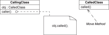
Figure 4.26. Delegation before Move Method refactoring.
This refactoring has a number of possible effects, depending on how it is implemented. The range and impacts are numerous enough that now is a good time to briefly introduce the other half of the EDPs. Recall from Section 2.2.4 the two-dimensional grid of method-similar EDPs in Figure 2.10. In Figure 4.27, you’ll find their method-dissimilar counterparts. The object type axis is flipped to exactly mirror the first figure, because these are equivalent to the ones we discussed before, except for the method similarity.
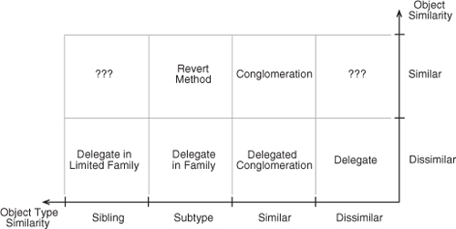
Figure 4.27. The design space with method similarity fixed to dissimilar.
In moving a method, the most general case is to move it to a related type, as in Figure 4.28. Such a move retains the Delegation instance, but it isn’t very interesting. Consider instead what happens when we move the method into the same class type as the calling method, as in Figure 4.29. Of course, now calling called() on the obj object doesn’t make much sense.

Figure 4.28. Delegation after Move Method refactoring: boring case.
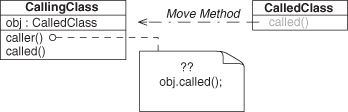
Figure 4.29. Delegation after Move Method refactoring: into same type.
There are two possibilities for fixing the mismatch within the method caller(). First, the caller() can elect to change the type of the object obj to the destination type. In other words, obj becomes an instance field of the same type as the type it is defined in. Second, caller() can eliminate the object completely and call its own instance using self. Which path is taken depends on the data usage needs of called(). If called() works primarily on data that is passed to it via caller(), and that data is instance data in the object encapsulating caller(), then that data can be accessed by called() directly and no longer needs to be passed as parameters. In this case, the second choice is a good one. Otherwise, the former design is preferred.
But what EDPs represent these two cases?
The first choice, changing the type of the object, results in a method-call EDP between differing methods of differing objects of the same type. By looking at Figure 4.27, as dissimilar object, similar type, we can see that this is an example of a Delegated Conglomeration. Much like Redirected Recursion, it involves two objects of the same type, working in concert. Unlike Redirected Recursion, however, in this case the two methods are dissimilar. Figure 4.30 illustrates this situation.
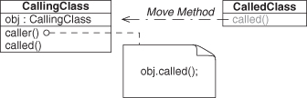
Figure 4.30. Delegation after Move Method refactoring: Delegated Conglomeration.
The alternative is to simply replace the called-upon object with self, eliminating the need for the field object, as shown in Figure 4.31, and resulting in the same dissimilar-method relationship as before, but now with a similar type, and a similar object. Figure 4.27 tells us that this is Conglomeration, which we discussed back in Section 2.2.4.
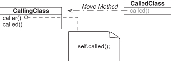
Figure 4.31. Delegation after Move Method refactoring: Conglomeration.
A similar duality occurs in other type-related decisions. If the method being moved is moved to a supertype of CallingClass, then we have either Trusted Delegation or Revert Method, depending on whether the called-on object is retained with the new type or eliminated in favor of super. Figures 4.32 and 4.33 demonstrate these outcomes. Trusted Delegation is extremely common and appears when the delegation is to be handed to a trusted group of related types and handled appropriately. This is easiest to do by using a polymorphic call on an object whose type is a superclass of the calling site. The superclass provides the trusted group of types, and the polymorphism means that it is handled appropriately.
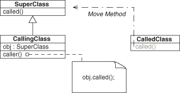
Figure 4.32. Delegation after Move Method refactoring: Trusted Delegation.
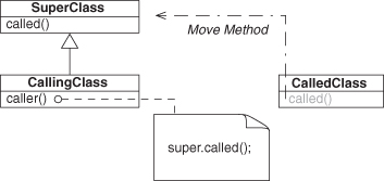
Figure 4.33. Delegation after Move Method refactoring: Revert Method.
Moving the method called to a sibling type of CallingClass results in a situation such as in Figure 4.34. As you might expect, it is an example of Deputized Delegation. Here, the trusted group of possible handling types is refined by restricting the polymorphic root to a sibling class of the calling site.
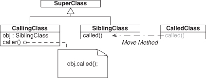
Figure 4.34. Delegation after Move Method refactoring: Deputized Delegation.
Finally, it should be noted that each of the transformations has a symmetric transformation that reverses it. We could just as easily go back to Delegation from any of the EDPs we transformed into and then on to any other endpoint EDP. In doing so, we traverse the entirety of Figure 4.27. With that one simple refactoring of Move Method, we routed between all six EDPs described.
As you can see, refactoring can have far-reaching effects in a design, even when the actions taken may seem trivial. It is important to keep in mind where your design is going to end up when undertaking refactoring efforts, and EDPs can help you plan ahead.
We can summarize the actions and resulting EDP transformations that we’ve discussed so far, as shown in Figure 4.35. You can see how applying Move Method, starting from Delegation, leads us to each of the other five EDPs on the left side of the diagram though the paths in bold. I’ve filled in the remaining possible transformations, including their mirror transformations. The use of the refactoring Rename Method to move left and right hints at a symmetry here, which we revisit in the next section.
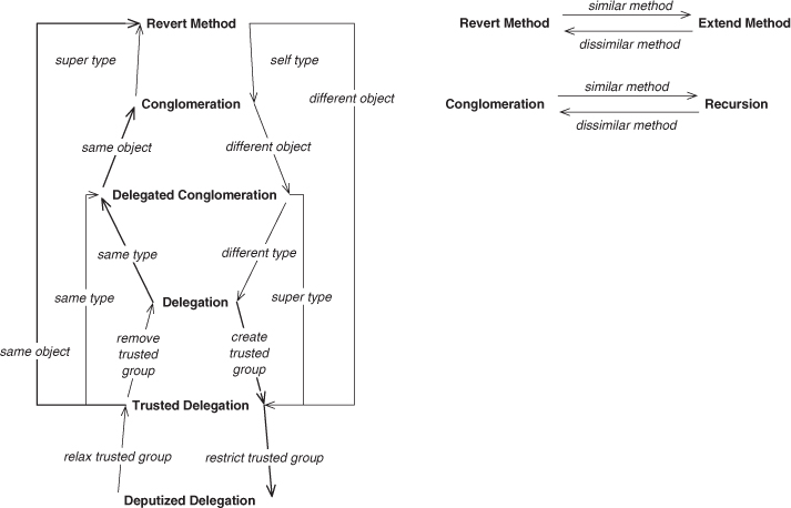
Figure 4.35. Summarizing refactoring effects so far.
4.4. The Big Picture
So far, this chapter has been a series of lessons on working with EDPs. You learned how to compose EDPs and other patterns into larger abstractions that have solid and workable definitions. You learned how to look for patterns that you already know of when reading about new patterns. We discussed isotopes, which allow design patterns and their implementations to be decoupled somewhat, allowing the encapsulation of design concepts and flexibility of expression in code. You even were introduced to the established libraries of refactoring approaches, saw how they work in concert with the EDPs, and saw how the well-defined relationships among the EDPs can facilitate refactoring planning.
We covered a wide range of topics, but now we can summarize them into some fairly simple charts and diagrams. The following figures provide a better sense of how the EDPs relate to one another. Some pattern names will be new to you. They haven’t been discussed in detail, but you’ll find them in the catalog chapters later in this book.
Figure 4.36 shows which EDPs are used by other EDPs and particularly which of the core EDPs are involved in the method-call EDPs. As you can see, there are some clear arrangements that form conceptual constellations. In some cases, the uses here are implicit, not explicit. Redirection, for instance, doesn’t explicitly use Retrieve, but because Redirection operates between two objects, Retrieve must be involved at some point to make one object available to the other for calling a method on it. On the other hand, Inheritance explicitly appears in the six EDPs that use subclassing.
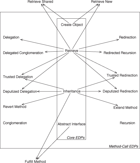
Figure 4.36. Implicit used-by relationships among the EDPs and selected other patterns.
First, notice that Retrieve is used heavily in the top portion of the digram. The EDPs that use Retrieve, as you would expect, involve two objects. These are the dissimilar-object method-call EDPs. Below them are the four similar-object EDPs.
Second, Inheritance dominates the middle section of the diagram. Method-call EDPs involved with Inheritance are those whose object types are in a subclass or sibling class typing relationship.
Note also that there is a symmetry in the diagram from left to right in the method-call EDPs. On the left are the EDPs between dissimilar methods; those on the right are EDPs between similar methods.
Finally, the patterns outside the core and method-call EDP boxes are those composed of two or more EDPs. Our old friend Fulfill Method uses both Abstract Interface and Inheritance, for instance.
I showed you part of the design space for method-call EDPs in Section 2.2.4, and it is now further fleshed out graphically in Figures 4.37 and 4.38. Each shows one half of the design space. Using this as a conceptual map as you read the EDP descriptions will help you see how they relate to one another.
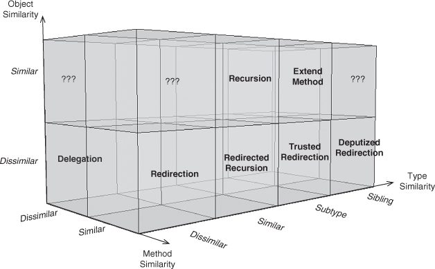
Figure 4.37. The full method-call EDP design space: dissimilar method.
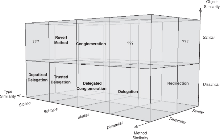
Figure 4.38. The full method-call EDP design space: similar method.
These two diagrams are aligned to match with the left and right sides of Figure 4.36. Figure 4.37 shows all method-call EDPs with dissimilar methods; it is the application of Figure 4.27, from our discussion in Section 4.3, onto the left long side of Figure 2.9. By turning this cuboid, we can look at the right long side, as in Figure 4.38, with the similar-method EDPs. Figure 4.38 is the application of Figure 2.10 onto the right long side of Figure 2.9. We discussed these EDPs in Section 2.2.4, when we considered EDPs with similar methods. These two diagrams are just the left and right sides of the same constructed space. They show where each EDP sits in the design space defined by the three similarity axes we started with: method, object, and object type. Each EDP is related to the EDPs surrounding it by explicit changes along those axes.
Describing those changes gives us the view in Figure 4.39, by building on what we showed in Figure 4.35. This lists the change required to transform each method-call EDP into another one, a single step at a time, to provide the atomic refactorings introduced in the previous section. This diagram will be useful as the requirements of a system change. You can better predict what the resulting system will look like if you know where you will need to end up in this EDP space. The figure on the left corresponds to Figure 4.37, with the dissimilar methods, and the figure on the right matches up with Figure 4.38, with the similar methods. If the method similarity property of an EDP changes, you shift from the left to the right, or vice versa.
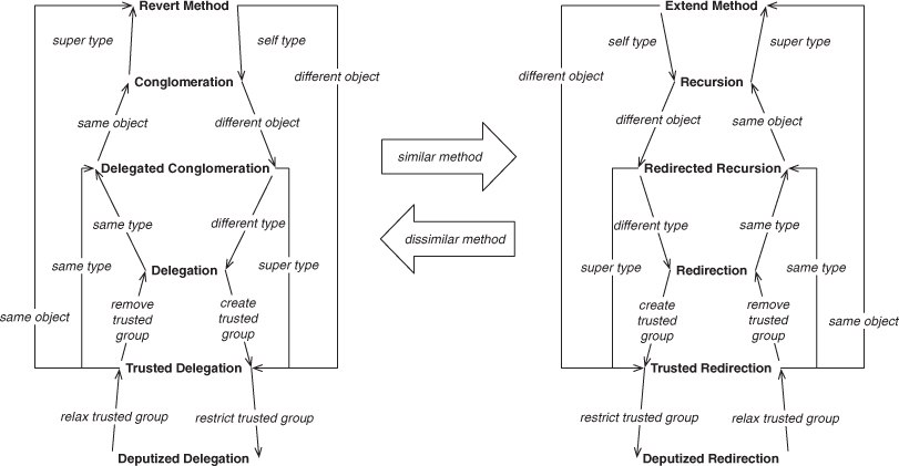
Figure 4.39. Method-call EDP refactoring relations.
For instance, if you implemented an instance of Recursion but need to break up the task among multiple objects, the arrow labeled different object points you directly to Redirected Recursion. If instead you find that the Recursion needs to be broken up into distinct subtasks, then you will be introducing new methods, and you know that you will no longer retain the method similarity. In that case, the large arrow in the middle labeled dissimilar method indicates you should slide left to the corresponding location on that tree, and you end up at Conglomeration. Each decision point that you have at your disposal will lead you to the proper, related concept.
When applying other refactoring actions, such as those from Fowler [19] and Kerievsky [24], you will find those actions moving your design elements along these routes. By knowing ahead of time how the EDPs will change and shift, you can better predict where your design will end up and manage potential problems.
These four diagrams are the conceptual core for understanding how the individual EDPs relate to each other and how they provide possibilities for design alterations. As you read the following catalogs, you might want to refer back to these figures to keep the larger picture in mind. While each design pattern is a self-contained concept, distinct relationships exist between them that form a richer system for working with and reasoning about them as a group.
4.5. Why You May Want to Read the Appendix
Okay, so I’m cheating a bit. I said that you didn’t have to understand any of the mathematics behind the EDPs to understand or use them. At this point, though, I’m going to offer a couple of claims based on the formalisms, and you can either take them on faith or you can go read the appendix to convince yourself of their validity. I hope you’re skeptical and dive in.
First off, taken as a whole, the formal body of EDPs provides complete coverage of the possible designs of object-oriented programming. Remember, this book touches on only one-quarter, at best, of the possible EDPs that exist. It is simply impossible to write an object-oriented program without using the EDPs. Yes, I know that’s a bold claim. Please read the formal tidbits for the full explanation. Hint: we established in Chapter 2 that binary relationships are the smallest relationships we can form. Given a finite number of things between which we can form relationships, there must be a finite number of possible relationships. Considering we’re starting with only objects, methods, fields, and types, how small do you think this set can get? If your answer is “about the size of the Elemental Design Patterns,” give yourself a cookie. That’s precisely what the EDPs are: a project to describe all of the possible smallest relationships in object-oriented programming in human terms so that we can share, understand, and use them more effectively. This book is a start; I hope you join in for the remainder of the discussion.
Second, the formalisms defined by the ρ-calculus are fundamentally where the EDPs come from. Most design patterns are created by finding repeating solutions by inspecting existing software systems. This approach lets us describe what we’ve done before, which is critical, but EDPs are unique in that they are definable from first principles, not just after the fact. To be sure, they are ubiquitously present in existing systems, and those instances are what we use to discern the intent of and write the specification for the EDP, just as with any other design pattern. The EDP design spaces defined by our orthogonal axes of context, however, provide a framework for filling in gaps we didn’t realize we had and for establishing exactly how the EDPs relate to one another.
The difference is akin to that between early mechanical engineers sharing blueprints for creations that they designed through trial and error and modern engineers able to simulate a complete design before ever fabricating a single part. The former is a description of what was tried; the latter prediction is based on formal reasoning and modeling. EDPs enable us to describe systems precisely and predict what impact even the smallest changes will have. Furthermore, as you saw with the reconstruction of Decorator, EDPs let us work with large abstractions at varying levels of granularity based on the needs of the moment. EDPs also enable us to describe new design patterns as they are found, composing their definitions in terms of existing abstractions. There’s really no end to the possibilities.
These features mean that EDPs allow us to do two crucial things with software systems. First, we can define and describe a piece of object-oriented software, any piece of object-oriented software, in terms designed to be used and understood by humans, regardless of the implementation language. We can capture the concepts in the code and express them in a way that is appropriate for a human to reason about. We showed that these small concepts quickly build into larger, more interesting concepts that solve real-world problems using best practices, such as the GoF patterns. We can document our software at multiple levels of granularity and choose which level of abstraction to operate on, depending on our needs in the moment. Second, and more enticingly, because these concepts are each formalized, and the manner in which they can interact is likewise formalized, the process of extraction, detection, composition, and description can be automated. Not coincidentally, that is the problem that SPQR was designed to solve.
That’s just the beginning.
4.6. Advanced Topics
This section introduces some advanced ideas that you might find intriguing. None of these are required for understanding the EDPs or reading the catalog. If you wish to skim (but hopefully not skip) this section, please feel free to do so.
4.6.1. Focused Documentation and Training
SPQR was originally intended to help document existing implementations of software, letting the concepts and abstractions described by the design pattern literature be found and documented directly from the implementation. The goal was that exposing these design pattern instances would give developers a better mental model of their systems, and they would have an easier path to produce that pesky documentation that we all hate doing as well as an easier time maintaining their codebases. Somewhere along the way, however, it became obvious that maybe we were looking at the wrong thing.
Design patterns are those concepts that we understand well. They are well documented, they are common, and they are a shared infrastructure among many systems. So if you find patterns in your software, great! You are using best practices to solve problems that others have already solved. Congratulations!
The entire documentation problem isn’t solved, however. You still must explain how you implemented the patterns you chose and how they interact with the rest of the system. Beyond that, however, the problems that others have solved are almost certainly not what makes your software unique. They are simply the skeleton on which you hang the features and clever bits of code that make your system more compelling to your clients, those that make it stand out in the marketplace. Those unique sections are the portions of your software that you need to spend your time addressing in documentation. Your coworkers and those who inherit your code will thank you for doing so.
In other words, the portions of your system that are describable by design patterns are not necessarily the parts that are critical to document. There’s still a documentation process to be performed. Delineating what portions of your system are covered by design patterns, however, tells you what you don’t have to spend time documenting. It’s the portion of the code that you don’t have to spend excessive resources training new hires on, the portion you don’t need to take hours to consider the impact of change to, the portion that you don’t need to make sure stays precisely intact to satisfy your customers.
The portions that are describable in high-level design patterns are those that are your infrastructure, precisely because they are portions that other people have already broken ground to solve. By understanding where your added value begins and ends, you can reduce the scope of your costs and effort to the parts that really matter to your bottom line.
And of course and you get world-class documentation for the remainder, because other people have already written it. You just have to point to their work.
4.6.2. Metrics
In any engineering discipline, quantitative metrics are a must to provide feedback, to ensure fidelity with predicted results, and to give insight. Software engineering is no different, and EDPs and their underlying formalisms make possible new ways to measure what we do.
Clarity of Expression We all have experienced software that is less readable than we would like. If we’re lucky, we may have experienced software that is extremely easy to read. Why is this? What makes some software make sense, while another system that does the same thing is a nightmare to work on?
Readability is not just a matter of selecting the right names and using the correct whitespace formatting. A piece of software that clearly expresses the concepts that it implements is considered readable. When the cognitive load on the programmer tasked with understanding it is low, it is considered clear. If the software contains the proper concepts, but they are hidden in a tangle of other things, then the intent and the meaning of what the original developer was trying to do is difficult to find. This is a qualitative process. We know clear code when we see it.
So what’s one way to ensure that the expression of a concept is clear and that the implementation is as readable as possible? Well, recall that we talked about isotopes. We can measure the relative clarity of the expression of the concept by how closely it matches the smallest, most direct, clearest expression of form. Usually, this is found in the canonical specification for a particular design pattern. If this canonical form was not already clear or not at its most reduced form, it is unlikely that it could have passed muster with the community. The specification of a design pattern is intended to be, above all else, clear.
For each additional step in a chain of reliances or each unnecessary piece in the implementation of an EDP, the developer has to work harder to see the relationship between the end points. It follows that we can measure the distance from optimal by counting the number of isotopic components that are unnecessary to expression of the concept but are present in the implementation. Basically, we count the extra pieces required to fulfill an individual pattern or concept instance.
Now, it may be (and probably is) true that those extra bits are necessary and useful for some other concept in the system, but their presence is obscuring that particular conceptual expression. We can use this as a measure of the clarity of a concept in the code. We can measure the conceptual readability, and we can do so automatically. Furthermore, we can provide guidance in clarifying these concepts by offering refactoring actions at the EDP-to-EDP level. It is up to the human engineers to decide which concepts are most important and need to be most clearly expressed, but at least this way they have a quantitative way to weigh the options and choose between refactoring plans.
Abstraction Density Using isotopes and EDPs to provide guidance for clarifying expression of intent works well for fine-grained precise measurement of specific concepts embodied in the code, but it is far from the whole picture. Another measure of code quality is to look at it in the aggregate and get a large-scale, 50,000-foot view of the system. Abstractions are a way for us to think about chunks of a system as a single concept, instead of having to deal with all details at all times. If you are told that a section of code is a for loop, that is much faster and cleaner than trying to describe the execution at the machine level, step by step. Likewise, each design pattern or concept is an abstraction that conveys a tremendous amount of information with minimal bandwidth. Further, as we showed that we can compose larger and higher-level abstractions from small ones, we can also describe quite large sections of a system at once if an appropriate abstraction can be found to encompass it.
It therefore follows that if we can describe 1,000 lines of code with one abstraction instead of 100 abstractions, we have less to manage in our heads at the same time. We can work with those thousand lines as a single whole and not have to worry about the internals. Larger sections of the system can be considered, mulled over, understood, and possibly refactored.
Overall, an implementation that can be described in a few high-level abstractions is preferable to one that must be described in many many small ones, all else being equal. We call this the abstraction density of the code, measured as the number of abstractions present in the code, weighted for their composition. In other words, an abstraction that encapsulates six smaller concepts is considered more important and preferable to the six small abstractions plus another small abstraction. In each case there are seven abstractions total, but in the former case, there’s only one that is required to be carried forward by a developer for basic understanding; in the latter situation, seven pieces of information must be mentally juggled.
The key phrase in the preceding paragraph is “all else being equal.” An abstraction may be formed from many pieces of information, but not all pieces of information will be part of a meaningful abstraction. We can measure the raw density in the code by measuring the number of context-free reliances it has. Remember, each reliance is a connection between two entities in the code; therefore each reliance is a connection that the developer must keep track of, but abstractions alleviate that burden. We call this raw number the information density of the code, presented as a number of reliances per line of code.
Taking the ratio of the two enables us to determine the number of abstractions per unit of raw information, the relative abstraction density (RAD). We can perform this analysis on a per-method, per-class, per-file, per-directory, or per-module granularity. It helps expose hot spots and potential trouble areas by alerting a project manager to the areas that are most likely to be problematic moving forward. Which isn’t to say that such code is wrong.
The lower the RAD, the more we would expect that area of the code to be problematic to work with. It may be efficient, optimized, behave perfectly, and have no bugs. We just wouldn’t consider it to be very maintainable when requirements change. Perhaps that’s exactly what an engineer needs from that code in that case. Knowing where the potential problem spots are before they bite you, however, allows you and your team to plan accordingly.
On the other hand, you may have a module with a very high RAD but that you know is riddled with bugs. You may decide to go ahead and stomp the bugs there, because the high RAD gives you confidence that the code is more readable and should be easier to work with. Perhaps in that case, the training overhead is low enough that you can bring on a couple more people to help out. Again, it’s a matter of getting the right information into the hands of the developers and project leads for decision making by humans.
4.6.3. Procedural Analysis
Throughout this discussion, there has been an underlying assumption that the implementation languages under consideration are object-oriented ones. After all, the formalisms are object oriented, UML diagrams are object oriented, and design patterns are object oriented, right? Well, no, not quite. Design patterns are just concepts like any other. Remember that some of them, such as Create Object and Inheritance, can be expressed in procedural languages with great fidelity. After all, that’s where they were first found. Object-oriented programming arose because it enforced best practices that were used in procedural languages.
It turns out that, given the right set of assumptions, procedural code can be analyzed for design patterns just as easily as object-oriented code can be. Remember the discussion of how to model global entities in C++, back in Section 2.2.2? In C, everything is global, but the same technique applies. At IBM Research, we were able to successfully generate meaningful UML diagrams for systems with hundreds of thousands of lines of code, written exclusively in C. EDPs were the link. Creating a fine-grained enough set of formalized concepts allows for the fine-grained analysis required to match procedural idioms to object-oriented assumptions. Entirely new vistas for visualizing and considering legacy code start to appear.
4.7. Conclusion
I trust this quick introduction to EDP has been interesting. I hope it has also been illuminating. Software is one of our most critical modern conveniences, one that we have an extremely tenuous grasp on. Right now we are more alchemists than engineers, sharing nuggets of gold among ourselves without knowledge of a periodic table. The EDPs, and the research that spawned them, are a way of creating a basis for a more rigorous approach to software engineering that is also very human. Software is a collaboration between man and machine, between human and silicon, and attempting to optimize it for one inevitably causes issues for the other. I propose that we let the machines handle the constructs, that we handle the concepts, and that we use design patterns with EDPs at the foundation as the bridge between the two.
You’re now ready to tackle the rest of this book, and I hope you find it as much of an eye-opener in the reading as I did in the writing. If we, as a community and an industry, can start thinking of software in terms of intent and focus on the concepts that form our designs instead of on the constructs that we use to explain them to a compiler, we can concentrate on what we do better than any machine.
We design. We collaborate. We communicate. We explain. We build.
We make the modern world run.
Let’s take it to the next level.