1.1 Numbers of pixels:
g.drawLine (10, 20, 100, 50); // 100 - 10 + 1 = 91 pixels
g.drawRect (10, 10, 8, 5);    // 2 * 8 + 2 * 5 = 26 pixels
g.fillRect (10, 10, 8, 5);    // 8 * 5 = 40 pixels
1.2 Program to draw many squares:
// ManySq.java: This program draws n x n sets, each
//   consisting of k squares, arranged as on a chessboard.
//   Each edge is divided into two parts with ratio
//   (1 - q)  : q. The values of n, k and q are program
              arguments.

import java.awt.*;
import java.awt.event.*;

public class ManySq extends Frame
{  public static void main(String[] args)
   {  if (args.length != 3)
      {  System.out.println("Supply n, k and q as arguments");
         System.exit(1);
}
int n = Integer.valueOf(args[0]).intValue(),
k = Integer.valueOf(args[1]).intValue();
float q = Float.valueOf(args[2]).floatValue();
new ManySq(n, k, q);
}
ManySq(int n, int k, float q)
{ super("ManySq: Many squares");
addWindowListener(new WindowAdapter()
{public void windowClosing(
WindowEvent e){System.exit(0);}});
add("Center", new CvManySq(n, k, q));
setSize (600, 400);
show();
}
}
class CvManySq extends Canvas
{ int centerX, centerY, n, k;
float p0, q0;
CvManySq(int nn, int kk, float qq){n=nn; k=kk; q0=qq; p0 =
1-q0;}
int iX(float x){return Math.round(centerX + x);}
int iY(float y){return Math.round(centerY - y);}
public void paint(Graphics g)
{ Dimension d = getSize();
int maxX = d.width - 1, maxY = d.height - 1,
minMaxXY = Math.min(maxX, maxY);
centerX = maxX/2; centerY = maxY/2;
float r = 0.45F * minMaxXY / n;
for (int x=0; x<n; x++)
for (int y=0; y<n; y++)
{ float xCnew = (2 * x - n + 1) * r,
yCnew = (2 * y - n + 1) * r,
xA, yA, xB, yB, xC, yC, xD, yD,
xA1, yA1, xB1, yB1, xC1, yC1, xD1, yD1, p=p0, q=q0;
if (x \% 2 + y \% 2 == 1){p = q0; q = p0;}
xA = xD = xCnew - r; xB = xC = xCnew + r;
yA = yB = yCnew - r; yC = yD = yCnew + r;for (int i=0; i<k; i++)
{ g.drawLine(iX(xA), iY(yA), iX(xB), iY(yB));
g.drawLine(iX(xB), iY(yB), iX(xC), iY(yC));
g.drawLine(iX(xC), iY(yC), iX(xD), iY(yD));
g.drawLine(iX(xD), iY(yD), iX(xA), iY(yA));
xA1 = p * xA+q * xB; yA1 = p * yA+q * yB;
xB1 = p * xB+q * xC; yB1 = p * yB+q * yC;
xC1 = p * xC+q * xD; yC1 = p * yC+q * yD;
xD1 = p * xD+q * xA; yD1 = p * yD+q * yA;
xA = xA1; xB = xB1; xC = xC1; xD = xD1;
yA = yA1; yB = yB1; yC = yC1; yD = yD1;
}
}
}
}1.3 To draw all edges as exactly straight lines and to make the vertices of inner squares lie exactly on the edges of their surrounding squares, use device coordinates, starting with a pair of very small squares (⋄ and □), and making the squares of each next pair exactly twice as large as those of the preceding pair.
1.4 The radius r of the circumscribed circles for the hexagons is supplied by the user. Based on this radius r, the following fragment (in which the variable names are self-explanatory) may be helpful:
int iX(float x){return Math.round(centerX + x/pixelSize);}
int iY(float y){return Math.round(centerY - y/pixelSize);}

void drawLine(Graphics g, float xA, float yA, float xB, float yB)
{  g.drawLine(iX(xA), iY(yA), iX(xB), iY(yB));
}
...

float halfr = r/2, horpitch = 1.5F * r,
  w = r * (float)Math.sqrt (3), h = w/2, marginleft,
                marginbottom;
int nhor = (int)Math.floor((rWidth - 2 * r) / horpitch) + 1,
    nvert = (int)Math.floor(rHeight/w);
marginleft = -rWidth/2 + 0.5F * (rWidth - halfr - nhor *
              horpitch);
marginbottom = -rHeight/2 + 0.5F * (rHeight - nvert * w);
for (int i=0; i<nhor; i++)
{ float x = marginleft + r + i * horpitch,
y0 = marginbottom + (1 + i \% 2) * h; // center of lowest
hexagon
int m = nvert - i \% 2;
// There will be nvert hexagons in each column for i = 0, 2, 4,
...
// while there will be nvert - 1 in each column for i = 1, 3, 5,
...
// Special case: if nvert = 1 and nhor > 1, then x is increased
by
// horpitch/2 because otherwise there will be an empty column on
the
// right.
if (nvert == 1 && nhor > 1)
x += horpitch/2;
for (int j=0; j<m; j++)
{ float y = y0 + j * w;
drawLine(g, x + halfr, y + h, x - halfr, y + h);
drawLine(g, x - halfr, y + h, x - r, y);
drawLine(g, x - r, y, x - halfr, y - h);
...1.5 We begin by computing the length
where
| u1 = xB — xA |
| u2 = yB — yA |
Since there should be a dash, not a gap, at each endpoint, and we use gap widths that are about equal to dashLength, we use the equality
| L = (2n − 1) × dashLength |
to compute n, the number of dashes. Writing h1 = u1/(2n − 1) and h2 = u2/(2n — 1), and denoting the dashes by i = 0, 1, . . . , n − 1, we draw dash i as a straight line with endpoints (xA + 2ih1, yA + 2ih2) and ((xA + (2i + 1)h1, yA + (2i + 1)h2).
2.1 After rotating the vector v = (v1}, v2) through 90° counter-clockwise, we obtain the vector (—v2, v1). Setting v = (v1, v2) = (xB — xA, yB — yA), we can therefore find the points D and C by adding (−v2, v1) to the coordinates of A and B, respectively.
2.2 To determine the position of P relative to the triangle ABC, we first test whether P lies on one of the three sides of the triangle, using the method onSegment, discussed in Section 2.10. If this is not the case, we test whether P lies inside ABC, using the method insideTriangle of Section 2.8. To do this properly, we need to know the orientation of A, B and C, for which we can use the method ccw of Section 2.6. If this orientation is clockwise, we use C, B and A, in that order, as the first three arguments of insideTriangle, so that the orientation of these arguments is counter-clockwise, as required. If P lies neither on a triangle side nor inside the triangle, it lies outside it.
2.3 Section 2.11 shows how to compute the distance between a point and a line. We perform this computation three times to determine which of the three triangle sides AB, BC and CA (or rather the infinite lines through these sides) lies closest to point P. We then use the method projection of Section 2.12 to compute the projection P′ of P on the triangle side in question (or on an extension of it). We draw both the triangle and the line segment PP′. If the projection point P′ lies on an extension of a side, we also connect this point to the side (AB, BC or CA), to indicate clearly which of the three lines has been used. For example, if P′ lies on an extension of BC (not between B and C), we can draw P′B.
2.4 Using the vector AB = u = (u1, u2) = (xB − xA, yB − yA) and the parameter λ, we can represent the line through A and B by the following vector form:
| A + λ u |
Similarly, with CD = v = (v1, v2) = (xD − xC, yD − yC) and parameter μ, the line through C and D is represented by
| C + λ v |
We find the intersection point S by solving
| A + λ u = C + λ v |
for λ (rewriting this vector equation as a system of two linear equations, using the x- and y- coordinates of A and C as well as u1, u2, v1 and v2). We then use the value of λ computed in this way to find
| S = A + λ u |
When deriving the desired value of λ, we will have to perform a division by the expression u2v1 − u1v2 (which is a determinant). If this determinant is zero, the lines AB and CD do not have a unique intersection point because these lines are parallel or coincide. Since the points A, B, C and D are obtained by clicking and there are (very small) rounding-off errors, we had better replace the condition
| determinant = 0 |
with this one:
| |determinant| ≤ epsilon |
where epsilon is some very small positive value. To make this independent of the units of length and in view of the way the determinant is computed, a reasonable value is
| epsilon = 10−3 (u12 + u22 + v12 + v22) |
2.5 To construct the bisector of angle B, we can compute the two vectors u = BA/|BA| and v = BC/|BC|. We can view these vectors as arrows starting at B and pointing to A and C, respectively. Since both u and v have length 1, the sum vector
| w = u + v |
can then be regarded as another arrow starting at B but lying on the desired bisector, so that, with parameter α, the vector form
| B + αw |
denotes the bisector of angle B. The intersection point D of this bisector and triangle side AC can then be found in the same way as in Exercise 2.4.
2.6 Using AB=u=(u1, u2)=(xB − xA, yB − yA) and v=(v1, v2) = (− u2, u1), we can write the following vector form for the perpendicular bisector of AB:
To find the circumcenter D of triangle ABC, write a similar vector form, say,
for the perpendicular bisector of BC. You can then find the intersection of these two lines by solving the vector equation
| A + 0.5u + λv = B + 0.5w + μt |
for λ (or μ). Then the circumcenter D is found as the point of intersection by using this value λ in Equation (F.1). After computing the radius r = |AD|, and using the methods iX and iY to convert real logical coordinates into integer device coordinates, you can draw the circle through A, B and C by writing:
int xLeft = iX(xD - r), xRight = iX(xD + r),
    yTop = iY(yD + r), yBottom = iY(yD - r);
g.drawOval(xLeft, yTop, xRight - xLeft, yBottom - yTop);
2.7 Compute the center C and the radius r of the circle through P, Q and R (see Exercise 2.6). Although there is a method drawArc in Java, this is not suitable for our present purpose because it requires angles to be specified (in degrees) as integers; especially if r is large, this may cause too large rounding-off errors with regard to both endpoints of the arc. We therefore simply use a great many straight line segments. We can do this by using Point2D objects for C, P, Q and R (see Section 1.5). Taking the orientation of P, Q and R into account by means of the method area2 of class Tools2D (see Section 2.13), we can write:
double alpha = Math.atan2(P.y - C.y, P.x - C.x),
       beta  = Math.atan2(R.y - C.y, R.x - C.x);
if (Tools2D.area2(P, Q, R) > 0)
   arcCcw(g, C, r, alpha, beta);
else
   arcCcw(g, C, r, beta, alpha);
The method arcCcw, used here, is listed below. Working counter-clockwise, it draws the arc with start and end angles alpha and beta and belonging to the circle with center C and radius r:
void arcCcw(Graphics g, Point2D C, double r,
   double alpha, double beta)
{  double pi2 = 2 * Math.PI, delta = beta - alpha;
   // Reduce delta to the interval [0, 2pi):
   delta = (delta + pi2) \% pi2;
   int X0=0, Y0=0,                     // Arc length = r * delta
      n = (int)Math.ceil(r * delta / 0.02); // 0.02 = rWidth/500
   double theta = delta / n;
   for (int i=0; i<=n; i++)
   {  double phi = alpha + i * theta,
         x = C.x + r * Math.cos(phi),
         y = C.y + r * Math.sin(phi);
      int X = iX((float)x), Y = iY((float)y);
      if (i > 0) g.drawLine(X0, Y0, X, Y);
      X0 = X; Y0 = Y;
   }
}
2.8 We can use the first of the two methods projection of Section 2.12 to find the projection D' of D on AB. Since the center M of the circular arc lies on the bisector of the angle ABC, we compute the unit vectors u = BA/|BA| and v = BC/|BC| and w = (u + v)/| u + v|, which start at B and point to A, C and M, respectively. We now have to find a scale factor λ, so that BM = λw. Since the cosine of the angle D′BM is equal to w ˙ v and using μ = |BD′|, we can compute λ = μ/(w ˙ v). We then find the endpoint E of the arc on BC and the center M as follows: E = B + μv, M = B + λw. Obviously, the radius of the arc is r = |MD′|. We can now compute the start and end angles α and β and draw the arc by choosing between two calls to the method arcCcw, depending on the orientation of the points A, B and C (see Exercise 2.7).
2.9 Refer to Exercise 2.8 for bisectors of angles and to Exercise 2.1 for the intersection of two lines. This will provide you with the centers of the four circles. You can use the radius of each circle as the distance of its center to one of its tangents. Recall that we have discussed the distance of points to lines in Section 2.11.
2.10 Use vector AB = (u1, u2) to find the points D = A + (—u2, u1), C = D + (u1, u2) and E = D + 0.5{(u1, u2) + (—u2, u1)}.
3.2 Similar to Exercise 3.1.
3.3 For shearing a set of points with reference to point C, we replace the shearing equations at the end of Section 3.2 with the similar ones
| x′ − xC = (x − xC) + a(y − yC) |
| y′ − yC = (y − yC) |
which reduces to x′ = x + a(y − yC), y′ = y.
The sharing operation will transform the circle into an ellipse with a non-horizontal axis, so that we cannot use the Java method drawOval. Therefore, for some large value of n, we approximate a circle with center C(xC, yC) and radius r by computing the following n points (xi, yi) of this circle:
| xi = xC + r cos iθ |
| yi = yC + r sin iθ |
where θ = 2π/n and i = 0, 1, . . . , n − 1. Instead of immediately connecting these points by straight lines, which would produce the circle, we first subject each xi to the above shearing formula.
3.4 Just compute the product AA−1 to obtain the identity matrix I. For example, the upper-left element of this product is equal to the inner product of the first row of A and the first column of A−1, which is a11(a22/D) + a12(−a21/D) = D/D = 1.
3.5 If there are many points for which we have to check whether they lie within a single triangle (or on an edge of it), the method insideTriangle of the following class is more efficient than the one discussed in Section 2.8, since most of the work is done here by the constructor, which need be called only once for that triangle:
class TriaTest
{  private Point2D C;
   private double a1, a2, b1, b2, c1, c2, d1, d2, det;

   TriaTest(Point2D A, Point2D B, Point2D C)
   {  this.C = C;
      a1 = A.x - C.x; a2 = A.y - C.y;
      b1 = B.x - C.x; b2 = B.y - C.y;
      det = a1 * b2 - b1 * a2;
      if (det != 0)
      {  c1 = b2/det; c2 = -a2/det;
         d1 = -b1/det; d2 = a1/det;
      }
   }

   double area2(){return det;}

   boolean insideTriangle(Point2D P)
   {  double p1 = P.x - C.x, p2 = P.y - C.y,
         lambda, mu;
      return (lambda = p1 * c1 + p2 * d1) >= 0 &&
          (mu = p1 * c2 + p2 * d2) >= 0 &&
          lambda + mu <= 1;
   }
}
4.1 Adapt the Java program for Bresenham's algorithm by drawing pixels from both of the endpoints towards the middle of the line. Either calculate where the middle point is beforehand or check on-the-fly (that is, within the loop) when the two pixels merge in the middle. There may be one or two middle points depending on whether the line consists of an odd or even number of pixels. If there is only one, it is a good idea to draw this pixel after exiting the loop. Check if your solution also works correctly for very short lines, consisting of one or two pixels. You solution should be very general in that it works for any two endpoints P and Q.
4.2 You should add a second for-loop in which the roles of x and y are interchanged. For example, the calls to putPixel should have ++y as their third argument instead of ++x as their second. If |yQ − yP| ≤ |xQ − xP|, the first loop should be executed; otherwise the second.
4.3 The following program produces only Figure 4.19. You should extend it, enabling the user to specify the two endpoints of a line segment and both the center and the radius of a circle.
// Bresenham.java: Bresenham algorithms for lines and circles
//                 demonstrated by using superpixels.
import java.awt.*;
import java.awt.event.*;
import java.util.*;

public class Bresenham extends Frame
{  public static void main(String[] args){new Bresenham();}

   Bresenham()
   {  super("Bresenham");
      addWindowListener(new WindowAdapter()
       {public void windowClosing(WindowEvent e)
               {System.exit(0);}});
      setSize (340, 230);
      add("Center", new CvBresenham());
      show();
   }
}
class CvBresenham extends Canvas
{  float rWidth = 10.0F, rHeight = 7.5F, pixelSize;
   int centerX, centerY, dGrid = 10, maxX, maxY;

   void initgr()
   {  Dimension d;
      d = getSize();
      maxX = d.width - 1;
      maxY = d.height - 1;
      pixelSize = Math.max(rWidth/maxX, rHeight/maxY);
      centerX = maxX/2; centerY = maxY/2;
   }
int iX(float x){return Math.round(centerX + x/pixelSize);}
int iY(float y){return Math.round(centerY - y/pixelSize);}
void putPixel(Graphics g, int x, int y)
{ int x1 = x * dGrid, y1 = y * dGrid, h = dGrid/2;
g.drawOval(x1 - h, y1 - h, dGrid, dGrid);
}
void drawLine(Graphics g, int xP, int yP, int xQ, int yQ)
{ int x = xP, y = yP, D = 0, HX = xQ - xP, HY = yQ - yP,
c, M, xInc = 1, yInc = 1;
if (HX < 0){xInc = −1; HX = -HX;}
if (HY < 0){yInc = −1; HY = -HY;}
if (HY <= HX)
{ c = 2 * HX; M = 2 * HY;
for (;;)
{ putPixel(g, x, y);
if (x == xQ) break;
x += xInc;
D += M;
if (D > HX){y += yInc; D -= c;}
}
}
else
{ c = 2 * HY; M = 2 * HX;
for (;;)
{ putPixel(g, x, y);
if (y == yQ) break;
y += yInc;
D += M;
if (D > HY){x += xInc; D -= c;}
}
}
}
void drawCircle(Graphics g, int xC, int yC, int r)
{ int x = 0, y = r, u = 1, v = 2 * r - 1, E = 0;
while (x < y)
{ putPixel(g, xC + x, yC + y); // NNE
putPixel(g, xC + y, yC - x); // ESE
putPixel(g, xC - x, yC - y); // SSW
putPixel(g, xC - y, yC + x); // WNWx++; E += u; u += 2;
if (v < 2 * E){y--; E -= v; v -= 2;}
if (x > y) break;
putPixel(g, xC + y, yC + x); // ENE
putPixel(g, xC + x, yC - y); // SSE
putPixel(g, xC - y, yC - x); // WSW
putPixel(g, xC - x, yC + y); // NNW
}
}
void showGrid(Graphics g)
{ for (int x=dGrid; x<=maxX; x+=dGrid)
for (int y=dGrid; y<=maxY; y+=dGrid)
g.drawLine(x, y, x, y);
}
public void paint(Graphics g)
{ initgr();
showGrid(g);
drawLine(g, 1, 1, 12, 5);
drawCircle(g, 23, 10, 8);
}
}4.4 Since an unknown number of curve segments are to be dealt with, we can use the Java concept of Vector, as we have also done in Section 1.5 and elsewhere to store Point2D objects representing the vertices of a polygon. In this case it makes sense to define a class CurveSegment and to use a Vector of CurveSegment objects, as this fragment shows:
class CurveSegment
{  Point2D[] P;
   CurveSegment(Point2D[] P){this.P = P;}
   ...
}
Writing
Vector curves = new Vector();
and using the array P, declared as
Point2D[] P = new Point2D[4];
containing the most recent four points, as we did in program Bezier.java in Section 4.6, we can add a new curve segment to curves by writing
curves.addElement(new CurveSegment(P));
The object curves can store several curves, each consisting of some consecutive elements.
4.5 In program Bspline.java of Section 4.7, pressing a key is interpreted as a signal to terminate the process of extending the curve. Insert the line
char ch = evt.getKeyChar();
in the method keyTyped so that you can use the character ch to differentiate between different characters entered by the user and to use them as commands.
Use a Vector element for each array representing a curve. Recall that we have used the statement
V.copyInto(P);
in the paint method of program Bspline.java, to copy the Vector object V into the array P. Using a different Vector object, say, curves, we can now add the array P to curves. The deletion of the last curve, as required by the d command, is then implemented as
curves.setSize(curves.size()−1);
4.6 Represent the grid on the screen by drawing ten equidistant horizontal lines that intersect ten equidistant vertical lines. If the user clicks on (or near) a point of intersection of these lines, transform the device coordinates to gridpoint coordinates, ranging from 0 through 9, and use these gridpoint coordinates to select P and Q. Draw the line PQ after Q has been defined. On the right of all these horizontal and vertical lines, display the strings
| algorithm[0], algorithm[1], . . . , algorithm[7] |
below each other, where the array algorithm is defined and initialized as follows:
String[] algorithm = {
   "int x=xP,y=yP,d=0,dx=xQ-xP,c=2*dx,",  // 0
   "    m=2*(yQ-yP);",                    // 1
   "for (;;)",                            // 2
   "{  putPixel(g, x, y);",               // 3
" if (x == xQ) break;", // 4
" x++; d += m;", // 5
" if (d > dx){y++; d -= c;}", // 6
"}"}; // 7As soon as the user has defined point Q, the line stored as algorithm[3] should be highlighted, indicating that the call to putPixel is about to be executed. You can realize this by using a variable, say i, indicating which of the above eight program lines (if any) should be displayed in red (or equal to, say, −1 if all program lines are to appear in black). All lines algorithm[j] with j ≠ i are displayed in black. You can use a switch statement to test the value of i in a method stepPressed. For example, you can write a fragment of the following form in the constructor of your canvas class:
addMouseListener(new MouseAdapter()
{  public void mousePressed(MouseEvent evt)
   {  // When the mouse is clicked, determine where
      // it is on the screen and do the appropriate
      //   action, if any.
      int xClick = 0, yClick = 0;
      // Get the coordinates
      xClick = evt.getX();
      yClick = evt.getY();
      // Check to see if STEP button was pressed
      if (xClick, yClick lies within the rectangle representing
                                                 the Step button)
         stepPressed();
      else
      if (xClick, yClick) lies within grid area
      {  ...
      }
      repaint();
   }
});
In the switch statement just mentioned, you should execute actions defined in the program line (stored in the algorithm array) that was previously highlighted and update the variable i mentioned above. Your method paint will use this variable i to display the correct program line in red and the others in black.
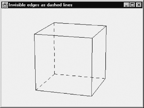
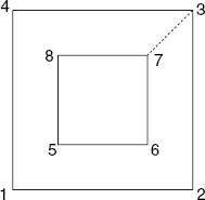
5.1 As Figure 5.11 shows, nine cube edges are visible and three are invisible. In the paint method of program CubePers.java, replace the calls to the method line with this fragment:
// Visible edges:
line(g, 0, 1); line(g, 1, 5); line(g, 5, 4); line(g, 4, 0);
line(g, 1, 2); line(g, 2, 6); line(g, 6, 7); line(g, 7, 4);
line(g, 5, 6);

// Invisible edges:
g.setColor(Color.blue);
line(g, 0, 3); line(g, 3, 2); line(g, 3, 7);
If you did Exercise 1.5 and have a class Lines, containing the method dashedLine, available, you may be able to replace the last two of the above lines with
dash(g, 0, 3); dash(g, 3, 2); dash(g, 3, 7);
while adding the following method to the class CvCubePers:
void dash(Graphics g, int i, int j)
{  Point2D P = obj.vScr[i], Q = obj.vScr[j];
   Lines.dashedLine(g, iX(P.x), iY(P.y), iX(Q.x), iY(Q.y), 8);
}
Figure F.1 shows the result of this solution with dashed lines.
5.2 There are two fillPolygon methods: one taking a Polygon object as an argument and the other taking two arrays x and y instead. In either case, do not forget to convert logical to device coordinates, using the methods iX and iY. Use setColor, with different colors before each of the three calls to fillPolygon.
5.3 To replace Figure 5.11, begin by sketching two cubes, say, one on either side of the xz-plane, and by assigning the numbers 0−7 to the vertices of the first and 8−15 to those of second cube. With this sketch, and using arrays w and vScr with length 16 instead of 8, you can easily update the program as requested. Remember to increase the value of objSize, which is used to compute both the object distance ρ and the screen distance d.
5.4 The following program demonstrates the principle of animation (with double buffering) for a simple case: a line segment is rotated about one of its endpoints, which is the center of the canvas. Every 20 ms, the angle α is increased by 0.01 radians and the line from the origin O (in the center of the canvas) to point (r cos α, r sin α) is drawn. The effect is that of a running clock with only one hand:
// Anim.java: Animation with double buffering.
import java.awt.*;
import java.awt.event.*;
public class Anim extends Frame
{  public static void main(String[] args){new Anim();}

   Anim()
   {  super("Animation (double buffering)");
      addWindowListener(new WindowAdapter()
       {public void windowClosing(WindowEvent e)
               {System.exit(0);}});
      add("Center", new CvAnim());
      Dimension dim = getToolkit().getScreenSize();
      setSize(dim.width/2, dim.height/2);
      setLocation(dim.width/4, dim.height/4);
      show();
   }
}
class CvAnim extends Canvas
   implements Runnable
{  float rWidth = 10.0F, rHeight = 10.0F, xC, yC, pixelSize;
   int centerX, centerY, w, h;
   Dimension d;
   Image image;
Graphics gImage;
float alpha = 0;
Thread thr = new Thread(this);
public void run()
{ try
{ for (;;)
{ alpha += 0.01;
repaint();
Thread.sleep (20);
}
}
catch (InterruptedException e){}
}
CvAnim(){thr.start();}
void initgr()
{ d = getSize();
int maxX = d.width - 1, maxY = d.height - 1;
pixelSize = Math.max(rWidth/maxX, rHeight/maxY);
centerX = maxX/2; centerY = maxY/2;
xC = rWidth/2; yC = rHeight/2;
}
int iX(float x){return Math.round(centerX + x/pixelSize);}
int iY(float y){return Math.round(centerY - y/pixelSize);}
public void update(Graphics g){paint(g);}
public void paint(Graphics g)
{ initgr();
if (w != d.width || h != d.height)
{ w = d.width; h = d.height;
image = createImage(w, h);
gImage = image.getGraphics();
}
float r = 0.8F * Math.min(xC, yC),
x = r * (float)Math.cos(alpha),
y = r * (float)Math.sin(alpha);
gImage.clearRect (0, 0, w, h);
// Every 20 ms, the following line is drawn.
// Each time, its endpoint (x, y) is a
// different point on a circle:gImage.drawLine(iX (0), iY (0), iX(x), iY(y));
g.drawImage(image, 0, 0, null);
}
}5.5 The following program produces two rotating cubes, illustrated by Figure 5.15. Remember, this program works only if the class file Rota3D. class (see Section 3.9) is available in the current directory:
// CubRot2.java: Two rotating cubes with double buffering.
//   Uses: Point2D (Section 1.5),
//         Point3D, Rota3D (Section 3.9)
import java.awt.*;
import java.awt.event.*;

public class CubRot2 extends Frame
{  public static void main(String[] args){new CubRot2();}

   CubRot2()
   {  super("Rotating cubes (double buffering)");
      addWindowListener(new WindowAdapter()
       {public void windowClosing(WindowEvent e)
               {System.exit(0);}});
      add("Center", new CvCubRot2());
      Dimension dim = getToolkit().getScreenSize();
      setSize(3 * dim.width/4, dim.height/2);
      setLocation(dim.width/8, dim.height/4);
      show();
   }
}

class CvCubRot2 extends Canvas
   implements Runnable
{  int centerX, centerY, w, h;
   Obj2 obj = new Obj2();
   Image image;
   Graphics gImage;

   double alpha = 0;
   Thread thr = new Thread(this);

   public void run()
{ try
{ for (;;)
{ alpha += 0.01;
repaint();
Thread.sleep (20);
}
}
catch (InterruptedException e){}
}
CvCubRot2(){thr.start();}
public void update(Graphics g){paint(g);}
int iX(float x){return Math.round(centerX + x);}
int iY(float y){return Math.round(centerY - y);}
void line(int i, int j)
{ Point2D P = obj.vScr[i], Q = obj.vScr[j];
gImage.drawLine(iX(P.x), iY(P.y), iX(Q.x), iY(Q.y));
}
public void paint(Graphics g)
{ Dimension dim = getSize();
int maxX = dim.width - 1, maxY = dim.height - 1;
centerX = maxX/2; centerY = maxY/2;
int minMaxXY = Math.min(maxX, maxY);
obj.d = obj.rho * minMaxXY / obj.objSize;
obj.rotateCube(alpha);
obj.eyeAndScreen();
if (w != dim.width || h != dim.height)
{ w = dim.width; h = dim.height;
image = createImage(w, h);
gImage = image.getGraphics();
}
gImage.clearRect (0, 0, w, h);
// Horizontal edges at the bottom:
line (0, 1); line (1, 2); line (2, 3); line (3, 0);
// Horizontal edges at the top:
line (4, 5); line (5, 6); line (6, 7); line (7, 4);
// Vertical edges:
line (0, 4); line (1, 5); line (2, 6); line (3, 7);
// Same for second cube:
line (8, 9); line (9, 10); line (10, 11); line (11, 8);
// Horizontal edges at the top:line (12, 13); line (13, 14); line (14, 15); line (15, 12);
// Vertical edges:
line (8, 12); line (9, 13); line (10, 14); line (11, 15);
g.drawImage(image, 0, 0, null);
}
}
class Obj2 // Contains 3D object data for two cubes
{ float rho, theta=0F, phi=1.3F, d;
Point3D[] s, w; // World coordinates
Point2D[] vScr; // Screen coordinates
float v11, v12, v13, v21, v22, v23,
v32, v33, v43, // Elements of viewing matrix V.
xe, ye, ze, objSize = 8;
Obj2()
{ s = new Point3D[16]; // Start situation
w = new Point3D[16]; // After rotation
vScr = new Point2D[16];
// Bottom surface:
s[0] = new Point3D( 1, −3, −1);
s[1] = new Point3D( 1, −1, −1);
s[2] = new Point3D(−1, −1, −1);
s[3] = new Point3D(−1, −3, −1);
// Top surface:
s[4] = new Point3D( 1, −3, 1);
s[5] = new Point3D( 1, −1, 1);
s[6] = new Point3D(−1, −1, 1);
s[7] = new Point3D(−1, −3, 1);
// Bottom surface:
s[8] = new Point3D( 1, 1, −1);
s[9] = new Point3D( 1, 3, −1);
s[10] = new Point3D(−1, 3, −1);
s[11] = new Point3D(−1, 1, −1);
// Top surface:
s[12] = new Point3D( 1, 1, 1);
s[13] = new Point3D( 1, 3, 1);
s[14] = new Point3D(−1, 3, 1);
s[15] = new Point3D(−1, 1, 1);
rho = 15; // For reasonable perspective effect
}
void rotateCube(double alpha){ Rota3D.initRotate(s[0], s[4], alpha);
for (int i=0; i<8; i++)
w[i] = Rota3D.rotate(s[i]);
Rota3D.initRotate(s[13], s[9], 2 * alpha);
for (int i=8; i<16; i++)
w[i] = Rota3D.rotate(s[i]);
}
void initPersp()
{ float costh = (float)Math.cos(theta),
sinth = (float)Math.sin(theta),
cosph = (float)Math.cos(phi),
sinph = (float)Math.sin(phi);
v11 = -sinth;
v12 = -cosph * costh;
v13 = sinph * costh;
v21 = costh;
v22 = -cosph * sinth;
v23 = sinph * sinth;
v32 = sinph;
v33 = cosph;
v43 = -rho;
}
void eyeAndScreen()
{ initPersp();
for (int i=0; i<16; i++)
{ Point3D P = w[i];
float x = v11 * P.x + v21 * P.y;
float y = v12 * P.x + v22 * P.y + v32 * P.z;
float z = v13 * P.x + v23 * P.y + v33 * P.z + v43;
Point3D Pe = new Point3D(x, y, z);
vScr[i] = new
Point2D(-d * Pe.x/Pe.z, -d * Pe.y/Pe.z);
}
}
}6.1 The desired input file is listed below:
1  1 −1 0
2  1  1 0
3  −1 1 0
4  −1 −1 0
5  0  0  −2
6  0  0  2
Faces:
1 2 3 4.
4 3 2 1.
5 6.
6.2 Use the vertices 1, 2 and 3 as triangle vertices in the plane z = 0, such that the origin O lies inside the triangle. Let vertex 4 be the origin and vertices 5 and 6 the same line endpoints as in the above solution to Exercise 6.1. Then, when specifying the triangle, use the invisible lines 1−4, 2−4 and 3−4 in the same way as the line 7−10 in Figure 6.14. In other words, define each of the two sides of the triangle as a rather complex polygon, specified as a sequence of ten numbers by visiting, for example, the vertices 1, 2, 4, 2, 3, 4, and so on, in that order, using minus signs for invisible lines.
6.3 See Section 6.4 for holes in polygons. Figure 6.27 was obtained by using a data file of the same structure as the above one (see Exercise 6.1), but with 16 vertices and four faces. Based on Figure F.2, the first of these faces was specified as follows:
1 2 3 −7 6 5 8 7 −3 4.
6.4 A simple solution to this problem is obtained by adding some code to draw all polygon edges (visible as well as invisible) as dashed lines. In addition to this, the visible edges are drawn as solid lines without any modification to the hidden-line algorithm. In other words, every visible edge is drawn as coinciding solid and dashed lines, which gives the effect of a solid line. Although HP-GL provides the command LT (Line Type) to draw dashed lines, we obtain better results if we draw our own, computed dashes, which are required for screen output anyway. Note that every dashed line in Figure 6.28 begins and ends with a dash of the same length as the other ones. To implement all this, modify the program file HLines.java (see Appendix D) as follows:
Disable back-face culling by deleting the following program line in the method buildLineSet.
if (n > 2 && pol.h > 0) continue;
Insert the following method in the class CvHLines (see also Exercise 1.5):}
void dashedLine(Graphics g, float xA, float yA,
      float xB, float yB, float dashLength)
{   float u1 = xB - xA, u2 = yB - yA,
       L = (float)Math.sqrt(u1 * u1 + u2 * u2);
    int n = Math.round((L/dashLength + 1)/2);
    float h1 = u1/(2 * n − 1), h2 = u2/(2 * n − 1);
    for (int i=0; i<n; i++)
    {   float x1 = xA +  2 * i * h1, y1 = yA + 2 * i * h2,
              x2 = x1 + h1, y2 = y1 + h2;
        drawLine(g, x1, y1, x2, y2);
    }
}
Just before the call to lineSegment in the paint method, almost at the end of the program file, insert the following line:
dashedLine(g, P.x, P.y, Q.x, Q.y, 8);
6.5 A program to generate an open book is shown below. It was executed twice (with n = 4 and n = 150) to produce the two open books of Figure 6.29. Refer to the analysis of Exercise 6.6 below for the way we design this type of program.
// BookView.java: Generating a data file for an open book.
import java.io.*;

public class BookView
{  public static void main(String[] args)
      throws IOException
   {  if (args.length != 4)
      {  System.out.println(
         "Supply nr of sheets, width, height and file name
"+
"as program arguments.");
System.exit(1);
}
int n;
float w, h;
FileWriter fw;
n = Integer.valueOf(args[0]).intValue();
w = Float.valueOf(args[1]).floatValue();
h = Float.valueOf(args[2]).floatValue();
fw = new FileWriter(args[3]);
int spineTop = 1, spineBottom = 2, outerTop, outerBottom;
float theta = (float)Math.PI/(n − 1);
float xTop = 0, xBottom = h;
fw.write(spineTop + " " + xTop + " 0 0
");
fw.write(spineBottom + " " + xBottom + " 0 0
");
for (int i=0; i<n; i++)
{ float phi = i * theta,
y = w * (float)Math.cos(phi),
z = w * (float)Math.sin(phi);
outerTop = 2 * i + 3; outerBottom = outerTop + 1;
fw.write(outerTop + " " + xTop + " " +
y + " " + z + "
");
fw.write(outerBottom + " " + xBottom + " " +
y + " " + z + "
");
}
fw.write("Faces:
");
for (int i=0; i<n; i++)
{ outerTop = 2 * i + 3; outerBottom = outerTop + 1;
fw.write(spineTop + " " + spineBottom + " "
+ outerBottom + " " + outerTop + ".
");
fw.write(spineTop + " " + outerTop + " "
+ outerBottom + " " + spineBottom + ".
");
}
fw.close();
}
}6.6 Before writing the program code we have to assign numbers to vertices and find mathematical expressions for the x-, y- and z-coordinates of these vertices. We will now discuss how this can be done for a sphere, but the same approach applies to any program that generates 3D data files.
The model of a sphere in question has two poles; let us assign vertex number 1 to the north pole. Since it is given that there are n horizontal slices, there will be n − 1 horizontal planes between them, each corresponding with a horizontal circle, or line of latitude, on the sphere. There will also be 2n vertical circles, or lines of longitude. Every vertex (other than the two poles) of our sphere model is a point of intersection of such a horizontal and a vertical circle. As for the faces, 2 × 2n of them are triangles at the two poles. There are n − 2 remaining horizontal slices, so that the number of remaining faces is equal to (n − 2) · (2n) = 2n(n − 2). Each of these is a parallelogram with two horizontal edges. Altogether, there are 4n + 2n(n − 2) = 2n2 faces, and, as we will see below, 2(n2 − n + 1) vertices. We will use two angles, θ and ϕ, as shown in Figure 5.3. Using a sphere radius 1, we can express the level of the n − 1 horizontal circles by their z-coordinate
| z = cos ϕ |
Writing δ = π/n, we will only use horizontal circles corresponding to the following angles:
| φ = i · δ (i = 1, 2, . . . , n − 1) |
On each of these circles we have to use 2n vertices, which correspond to the angles
| θ = j · δ (j = 0, 1, . . . , 2n − 1) |
Thus, each pair (i, j) is associated with a vertex, so that we can devise a means of associating a vertex number with it. Since 1 has been used for the north pole, we start with vertex number 2 on circle i = 1. With 2n vertices on each horizontal circle, the first vertex number available for circle i = 2 will be 2n + 2, and for circle i = 3 it will be 4n + 2, and so on. In general, on circle i, we begin with number (i − 1) · 2n + 2. Since on each circle there are 2n vertices, identified as j = 0, . . . , 2n − 1, we have
| number for vertex (i, j) = (i − 1) · 2 n + 2 + j |
As we have seen in Section 5.2, the x-, y- and z-coordinates for this vertex (i, j) is computed as x = sin ϕ cos θ, y = sinϕ sin θ and z = cos ϕ, where θ and φ depend upon i and j as shown above.
Finally, we have to assign a vertex number to the south pole. As we already have used 1 + (n − 1) · 2n vertex numbers, the one for the south pole will be
| 1 + (n − 1) · 2n + 1 = 2 (n2 − n + 1) |
which is also the total number of vertices.
6.7 Analyze this problem in the same way as was done for Exercise 6.6. Here each triangle (at the south pole) and each parallelogram is to be specified both counter-clockwise and clockwise, since either side of the curved surface can in principle be visible. Unlike Exercise 6.6, we had better use the variable n for the number of slices of half the sphere in this problem, so that there are 4n instead of 2n vertices on every horizontal circle that we use, giving altogether n · 4n + 1 = 4n2 + 1 vertices.
6.8 Use program arguments for the numbers of squares in each of the three directions x, y and z. Remember, the word Faces can occur only once in the file, so we have to specify the vertices of all cubes before we start specifying the faces.
6.9 Let us start with a torus such as the one in Section E.3, that is, a horizontal one with O as its center, and let the second torus be a vertical one, with its center on the positive x-axis. We will make the sizes of the tori and their numbers of vertices identical; only their positions are different. As in Section E.3, the size of a torus (and its shape) is completely determined by the radii R and r, where r = 1. Since the hole in each torus must be wide enough for the other to pass through, it is required that R ≥ 2r, that is, R ≥ 2.
For each vertex of the first torus, there is a corresponding one on the second. As we have seen in Section E.3 there are n2 vertices for each torus, so we can use the numbers i and i + n2 for each pair of corresponding vertices. To obtain the second torus, we have to shift the first one a distance R towards the positive x-axis, after which we turn it through the x-axis though 90°. (Because of this special angle, no complicated computations are required for this rotation, so it is not worthwhile to use the class Rota3D of Section 3.9 in this case.) Writing (x, y, z) for vertex i and (x′, y′, z′) for the corresponding vertex i + n2, we now have x′ = x + R, y′ = − z, z′ = y.
Although, in the first part of 3D data files, we usually supply the vertices in ascending order of the vertex numbers, this is not required. It is therefore possible to write pairs of lines of the following form in the first part of the data file:
| i x y z |
| i + n2 x′ y′ z′ |
Similarly, in the second part of the file, we can write faces in pairs, with vertex numbers in the second face of each pair n2 higher than those of the first of that pair. In this way, the desired program for two tori can be obtained from Torus.java by adding only a few statements.
6.10 If necessary, you might refer to the method genCylinder in program Cylinder.java of Section 6.6 for the cylindrical pole in the middle of the staircase. If you do, bear in mind that the situation here is simpler because this cylinder is solid (as is the case in program Cylinder.java with rInner = 0). You can use program Beams.java of Section E.4 to see how the steps can be constructed, or you can use the class Rota3D (see also Exercise 5.5), provided that you also perform a translation, adding a constant to the z-coordinates of each new step. As for the railing, recall that the data file, after the word Faces, can contain line segments specified as two vertex numbers followed by a period, as discussed in Section 6.5.
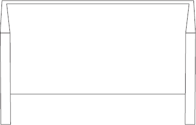
7.1 In Figure F.3, the two outer faces on the left and right are parallel, but the corresponding inner faces are not, as the distances 18 and 19 indicate. The latter faces, which are visible here, become invisible if we view the object from very far away, as Figure F.4 shows.
Recall that, with eye coordinates, the x-axis points to the right, the y-axis upwards and the z-axis towards us. Let us focus on the inner face that is visible in Figure F.3 on the right but invisible in Figure F.4. Estimating the normal vector n = (a, b, c) and the value h, as specified in the exercise and discussed in Section 5.5, for this face, we find:
a is almost equal to −1, because n almost points toward the negative x-axis;
b is almost zero, but positive because we view the object slightly from above;
c is almost zero, but negative because n points a little to the back.
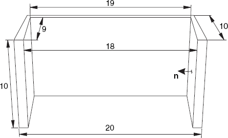
These values, and in particular c, are independent of the viewing distance. By contrast, the inner product h = n · x, where x is a vector from the viewpoint E to any point of the face in question, depends on the viewing distance. You should verify this by drawing a sketch similar to Figure 7.12 but applied to this example. As a result, you will find that h is negative in Figure F.3 but positive in Figure F.4. This example demonstrates that, to determine if a face is a back face, we should use the sign of h, not that of c. The correct practice of using h for this purpose is equivalent to back-face culling based on the orientation of three points: if this orientation on the screen is the same as when the object is viewed from outside, the face is visible. Using c instead of h would be equivalent to using the eye coordinates x and y instead of the screen coordinates in determining the orientation of image points. This would work correctly for most situations, but it may result in wrongly deciding that faces are invisible, especially if the object is viewed from nearby, as Figure F.3 illustrates. Recall that we also briefly discussed this in Section 7.1.
7.2 We can use back-face culling to decide which faces of the cube are visible. Refer to the solutions to Exercises 5.4 and 5.5 for the implementation of animation and rotation, respectively.
7.3 In the previous exercise we could have realized the effect of a rotation about a vertical axis by changing the angle θ and leaving the cube unchanged. This is no longer the case here because we now want to use two rotations. Figure 7.13 was obtained by rotating each cube about one of its vertical edges, with different rotation speeds, the latter simply meaning that we use different angles in each step. As in the solution to Exercise 5.5, you need to supply only one method run, in which only one infinite loop occurs.
7.4 Change the class CvPaint (in the program file Painter.java) as follows:
At the beginning of the class CvPaint, before {, add the line
implements Runnable
After {, add the following lines:
Image image;
Graphics gImage;
double sunTheta = 0;
Thread thr = new Thread(this);
Insert the method run, similar to the one given above for Exercise 5.4, but containing statements to update the spherical coordinate sunTheta (see Section 5.2) and the variables obj.sunX and obj.sunY; you can use a constant value for sunPhi, which makes obj.sunZ also a constant. By using spherical coordinates, with radius ρ = 1, the light vector will have length 1.
Insert the program lines
int w, h;
CvPainter(){thr.start();}
public void update(Graphics g){paint(g);}
Modify the paint method, using the variables image and gImage as well as g, in about the same way as was done in program Anim.java, listed above as help for Exercise 5.4.
7.5 For the format of the desired file see the file for Exercise 6.1. As for the program to generate 3D data files, refer to Section 6.6 and Appendix E, if necessary.
8.1 In the program FractalGrammars.java, there is the following fragment, which draws a line from the current point (xLast, yLast) to the new point (xLast + dx, yLast + dy), which, after the call to drawTo, will automatically be the current point (xLast, yLast).
case 'F': // Step forward and draw
   // Start: (xLast, yLast), direction: dir, steplength: len
   if (depth == 0)
   {  double rad = Math.PI/180 * dir, // Degrees -> radians
      dx = len * Math.cos(rad), dy = len * Math.sin(rad);
      drawTo(g, xLast + dx, yLast + dy);
   }
Besides xLast and yLast, introduce the variables xCorner and yCorner, indicating the cornerpoints that we will not really visit because of the rounded corners. Each time, instead of drawing a line as discussed above, draw two lines. The first is one from the current point (xLast, yLast) to (xCorner + dx/4, yCorner + dy/4) to approximate the rounded corner. After this, the point just mentioned is now automatically stored as the new point (xLast, yLast) to enable you to used drawTo again. Then update the variables xCorner and yCorner by increasing them by dx and dy, respectively, so they indicate the next cornerpoint. Then you draw the second line, from the current point (xLast, yLast) to (xCorner — dx/4, yCorner — dy/4). Note that this last line is half as long as the full line drawn in the above fragment, since a quarter of it at the beginning and a quarter of it at the end are now replaced with the approximated rounded corners.
8.2 In the paint method of the program Koch.java in Section 8.2, there is only one call to drawKoch preceded by setting dir = 0. All you have to do is add two other such calls, each preceded by assigning an appropriate value to dir so that the turtle starts in the right direction.
8.3 You can generate a random number between 0 and 1 by calling Math. random(), and derive the thickness of a branch from the height of that branch in the tree. A line of any thickness can be realized by using the method fillPolygon.
8.4 This hint is based on the program FractalGrammars.java and the string grammar Tree2 of Section 8.3. In this example, we have
| strX = "F[+X]F[− X]+X" |
Each time the second F in this string is encountered a branch is drawn that should have a leaf at its end. So in the switch statement you should add a fragment to draw a leaf in the case F part after the call to drawTo, provided that the position counter i for strX is equal to 5. One way of drawing a closed figure that approximates the shape of a leaf is to draw a sequence of filled circles (by means of drawOval) whose centers lie on a line that has the same direction (dx, dy) as the branch in question.
8.5 Use methods iX and iY to convert logical to device coordinates and methods fx and fy for the inverse conversions. Restricting this discussion to x-coordinates, we can use
int iX(float x)
{  return (int)(xDevCenter + (x - xLogCenter)/pixelSize);
}

float fx(int x)
{  return xLogCenter + (x - xDevCenter) * pixelSize;
}
As usual, we use d defined as
Dimension d = getSize();
Let us denote the current boundaries of the logical x-coordinates by xLeft and xRight. For example, we can initially set these boundaries equal to those of the device coordinates, that is, to 0 and d.width(), respectively. In the method mouseReleased, we obtain the device coordinates xs and xe for the left and right boundaries of the cropping rectangle. We then apply the method fx to these to obtain the corresponding logical coordinates, writing, for example,
xLeftNew = fx(xs);
xRightNew = fx(xe);
Then these new values are assigned to xLeft and xRight, and used to compute
pixelSize = Math.max((xRight - xLeft)/d.width,
                     (yTop - yBottom)/d.height);
xLogCenter = (xLeft + xRight)/2;
Let us now discuss the plausibility of these statements (rather than proving them rigorously). Normally, mouseRelease provides us with a range (xs, xe) that is smaller than the width of the drawing rectangle. Then after applying fx and fy, the new logical x-range (xLeft, xRight) will also decrease, and the same applies to pixelSize. As a result of the latter, the value added to xDevCenter in the above method iX will be larger than it was before, so that the figure will appear on a larger scale. As for panning, let us assume that the new x-range selected by the user is on the left half of the screen. Then the new center xLogCenter of the logical x-range will be smaller than it was before, which will increase the value computed by the method iX. This should indeed be the case, since the part of the image displayed in the selected x-range on the left half of the screen should be displayed in the center of the drawing rectangle, or, in other words, it should shift to the right.
8.6 Modify the MandelbrotZoom.java program and the paint method for Julia sets. Combine the two programs so that the latter will draw Julia sets in a side window.