
Software applications should simulate (model) the real world with close affinity to the problem domain. When the real world changes, which inevitably will occur, your application should be sufficiently malleable or extensible to adapt to the new reality. C# is a direct descendant of C++. Further, C++ is indirectly derived from Simula (short for simulation). Simula, Simula 1, and then Simula 67 were created in the 1960s at the Norwegian Computing Center in Oslo, Norway, and were considered the first object-oriented programming languages. Simula was developed to create simulations of real-world problems. Bjarne Stroustup merged C and Simula to create C++. Of course, C# is heavily influenced by C++.
The example used in this chapter is a software application for customer banking at a bank branch. The problem domain is customers entering a bank and using one of the available services, such as bank withdrawal, deposits, or wiring money. The application is used by bank management to simulate the retail banking environment. This is used for planning purposes to assure the correct balance of resources at a branch. One of the first steps is to create scenarios that in aggregate model the various dimensions of the problem domain. From those scenarios, you can identify potential objects, behaviors, and attributes. For example, select the nouns from the problem domain as possible future objects. See 2-2 for some of the nouns found in the retail banking scenarios. The complete scenarios are available at the Web site for this book, which is http://www.microsoft.com/learning/en/us/books/12792.aspx.
Table 2-2. Nouns in the retail banking scenarios
Account holder | Social Security number | Street address | City |
State | Zip code | Phone number | Checking account |
Savings account | Teller | Bank branch office | Transaction |
The next logical step is to identify the verbs and verb phrases in the problem domain. These are the potential behaviors. 2-3 is a list of the possible behaviors found in the retail banking scenarios.
Table 2-3. Verbs and verb phrases in the retail banking scenarios
Open checking | Open savings | Close checking | Close savings |
Get teller | Deposit checking | Withdraw checking | Deposit savings |
Withdraw savings | Transfer money | Wire money | Charge fee |
Finally, from the scenarios, identify the adjectives or other descriptive phrases that are potential attributes. 2-4 is a list of some of the adjectives from the retail banking scenarios.
Table 2-4. The adjectives in the retail banking scenarios
Balance | Age | Gender | Open date |
Close date | Last transaction | Branch | Routing number |
Account number | Opening teller | Interest | Security alert |
2-2, 2-3, and 2-4 represent a short list of items found in the problem domain for retail banking. The actual list of valid items would be considerably longer. At this phase of the design, include everything. Do not prejudge the usefulness of a particular item in the problem domain. For example, bank branch office is a noun found in the problem domain. Even though it is likely to be removed in a later phase, include bank branch office in the list of potential objects. While in the design phase, it is imperative that implementation decisions be deferred to later. Considering implementation details prematurely detracts from the purity of the design process. Let the design dictate the implementation and not vice versa. For example, in a later phase, objects that do not communicate with other objects will be identified. If an object does not communicate or associate with another object in your problem domain, that entity is probably not useful from the perspective of your application and can be removed. Based on the scenarios for our application, bank branch office does not collaborate with any other objects. At that time, and not earlier, the design would dictate that the bank branch office be removed from the list of objects. In this circumstance, design analysis drove the decision to remove the object.
There should be a way to clearly model various phases of the software development life cycle, including the design analysis. A single syntax that everyone, regardless of his or her role in the software development life cycle, will understand. That is the goal of UML. It provides a consistent and standardized syntax for modeling aspects of the software development life cycle.
UML is a formal language for modeling software system design and architecture. UML documents the objects, behaviors, attributes, collaboration, and associations through a variety of diagrams. These diagrams provide different perspectives on a software system. For example, the class diagram documents the classes found in a software system and their interaction. While class diagrams are static, sequence diagrams are dynamic and document the sequence of interactions between elements of the software system. Diagrams, such as the class and sequence diagrams, are essential. UML 2.0 defines 13 diagrams:
Activity diagram. The activity diagram can be at either a conceptual or functional level. This diagram models a complex use case or application logic.
Class diagram. The class diagram lists the classes of the software system. For each class, the behaviors, attributes, and relationships are detailed.
Communication diagram. The communication diagram depicts the dynamic aspect of a software system. It documents the messages (communication) between classes collaborating on a single task.
Component diagram. The component diagram depicts the relationship between subsystems or groups of components. This provides an overview of the software system.
Composite structure diagram. The composite structure diagram highlights the internal architecture of a classifier. This diagram consists of several elements, such as parts, collaborations, and ports. Parts represent the composition of a classifier. Collaborations define behaviors that intersect parts and the surrounding classifier. Ports represent dependencies that are exposed from a part or imported from the external environment.
Deployment diagram. The deployment diagram shows the hardware configuration necessary to deploy a software system, which includes defining the relationship between the hardware infrastructure and the software system.
Interaction overview diagram. The interaction overview diagram is a derivative of the activity diagram but shows an overview of the flow from various interactions. In the diagram, nodes often represent interaction overview diagrams.
Object diagram. The object diagram describes the relationship between object instances with a software system at a particular point in time. You can also display a snapshot of the state of each of the instances.
Package diagram. The package diagram provides an overview of the software system by grouping related classifiers. Any relationships or dependencies between the groups are then depicted in the diagram.
Sequence diagram. The sequence diagram is a dynamic graph and shows the logical flow of messages within a software system or subsystem. This is probably one of the most important and commonly used diagrams.
State machine diagram. The state machine diagram is a dynamic diagram and depicts the confluence of state and behavior. This diagram shows the behavior of a software system based on the state of certain object instances at a point in time.
Timing diagram. The timing diagram graphs the behavior and resulting change of state of one or more object instances against a timeline.
Use case diagram. The use case diagram highlights the relationships between actors and use cases.
You can create UML diagrams with Microsoft Office Visio 2007. Currently, you are not able to create UML diagrams directly in Visual Studio. Microsoft Office Visio 2007 allows you to visualize complex concepts and transform single dimensional textual representations into dazzling reports with depth. This means you can convert stale columnar reports to images that instantly convey a concept. Visio allows individuals who are not artistically inclined—like me—to create compelling graphics without hiring a professional. Visio has a variety of tools and shapes useful for creating a variety of technical documents. Visio documents can then be exported as a Web page, PDF file, or other formats. To save a file in PDF format, you must first install the Microsoft Save As PDF add-in for the 2007 Microsoft Office system. In Microsoft Office Visio 2007, you can create several UML diagrams to model a software system.
Use Case diagram
Collaboration diagram
Sequence diagram
Component diagram
Deployment diagram
Activity diagram
A variety of Static Structure diagrams, such as the Class or Object diagram
Microsoft Office Visio 2007 does not natively support UML 2.0 diagrams. There are a variety of sources for UML 2.0 stencils for Visio. Here are some resources:
Visio Café: http://www.visiocafe.com/
Software Stencils: http://softwarestencils.com/uml
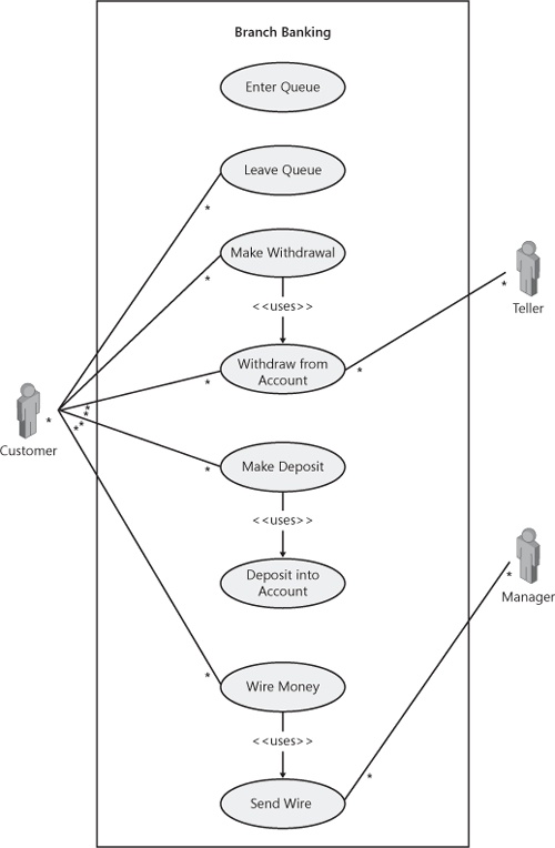
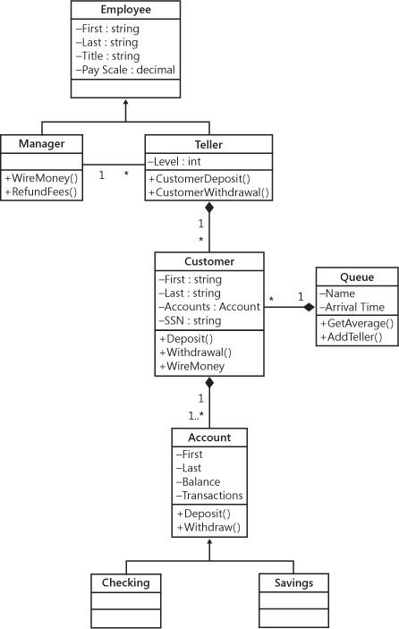
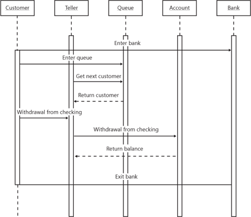
The following diagrams were created using Microsoft Office Visio 2007. 2-2 is a Use Case diagram. 2-3 is a Class diagram, while 2-4 is a Sequence diagram. The three diagrams are only partially completed for the retail banking software application and available for demonstrative purposes only.
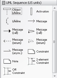
Microsoft Office Visio 2007 provides templates to make diagramming a bit easier. These templates provide a core set of shapes for creating illustrations and diagrams. Templates consist of stencils and sometimes toolbars and menus that are added to the Microsoft Office Visio 2007 environment. Stencils have shapes that target a specific objective, such as creating a class diagram. A stencil has shapes and styles. You can drag shapes from the stencil onto a Visio document as part of creating an illustration. The Visio document can contain shapes from more than one stencil. For example, the UML Model Diagram includes several stencils: UML Collaboration, UML Component, UML Sequence, and others, which contain shapes for drawing Collaboration, Component, and Sequence diagrams correspondingly. The UML Sequence stencil has the common shapes used in a Sequence diagram, as shown in 2-5.
Currently, one of the new features planned for Visual Studio 2010 is UML Modeling. Rosario is the next revision of Visual Studio after Visual Studio 2008. UML Modeling will be available in the Architecture Edition and will support UML 2.0 diagrams. You can forward or reverse engineer the diagrams, depending on whether the code base is already established. Community Technology Previews (CTPs) for Rosario are available at the Microsoft Web site. The release date for Rosario is probably sometime in 2009. However, Microsoft has not published a firm release date, and until the software reaches Beta 1, features are subject to change.
2-3 is a State diagram that was created with Microsoft Office Visio 2007. This section is a tutorial for creating a portion of that State diagram and a general overview of Microsoft Office Visio 2007. For a comprehensive book on Microsoft Office Visio 2007, I would recommend Microsoft Office Visio 2007 Inside Out, authored by Mark Walker and published by Microsoft Press.
Creating a UML diagram begins with selecting the appropriate template in Microsoft Office Visio 2007. Start Microsoft Office Visio 2007. From the menu, choose File, and then choose New. From the New submenu, select Software and Database. A list of diagrams should appear on the drop-down menu. Choose UML Model Diagram (Metric) or UML Model Diagram (US Units) from this list, depending on your preference. After selecting the template, an empty environment, including a new Visio document, is presented. Conversely, an existing document can be opened from the menu with File and then Open or simply by selecting the relevant document from the most recently used (MRU) list.
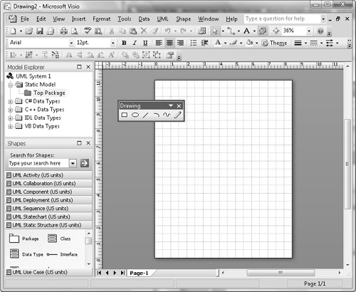
The Microsoft Office Visio 2007 environment includes a Visio document, Shapes pane, Model Explorer, default toolbars, and menu. 2-6 shows the standard environment for a UML diagram.
The UML Model Diagram stencil, as expected, has several stencils for creating an assortment of UML diagrams:
UML Activity stencil contains shapes for creating Activity and Interaction overview diagrams.
UML Collaboration stencil contains shapes for creating Collaboration (UML 1.2) and Communication diagrams (UML 2.0).
UML Component stencil contains shapes for creating Component diagrams.
UML Deployment stencil contains shapes for creating Deployment diagrams.
UML Sequence stencil contains shapes for creating Sequence diagrams.
UML Statechart stencil contains shapes for creating State machine diagrams.
UML Static Structure contains shapes for creating Class and Object diagrams.
UML Use Case contains shapes for creating Use Case diagrams.
You can drag shapes from a stencil onto the Visio document. The drawing document is similar to most graphics windows, where graphical elements can be selected (handles will appear), dragged, resized, deleted, edited, and so on. Some shapes can be connected to other shapes. For example, an Interface shape can be connected to a Class shape. Both of these shapes are found in the UML Static Structure stencil. When connecting, the intersection of the two shapes is highlighted. This is the same behavior observed when connecting any two shapes.
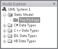
The Model Explorer contains all of the models for a software system, which could include several diagrams. It is organized into models and packages that provide a hierarchal structure to the Model Explorer. Each model represents a model of a software system, while packages offer different views of a software system. 2-7 shows the default Model Explorer of Microsoft Office Visio 2007. The Static Model is the root folder for any new UML Model diagram. You can customize this folder as desired. Each model has one top package, appropriately called Top Package, which is the root package for the model. There is only one root package in the model—all other packages are organized within this package. Packages can contain other packages. In addition, a package can contain diagrams. Collectively, the diagrams in a package represent a particular view of a model.
Here are steps to create the correct model and related packages for the retail banking system. The top model will be renamed YourName Bank to represent your banking company. We will create a package called Retail Banking for branch banking. There will be a second package called Private Banking to model a software system for high–net worth clients.
Rename the Static Model to Your Bank. Open the context menu (right-click) for the Static Model folder, and choose Properties. Enter the new name in the Name field.
Rename the Top Page package similarly using the Properties window. Rename the top package to Bank.
Add two packages to the Bank package. Open the context menu for the Bank package and choose New. Select Package from the list of choices. In the UML Package Properties, name the package Retail Banking. Repeat the same steps to create a second package, which should be named Private Banking.
Next, let us add the appropriate diagrams to the Retail Banking package. Choose New from the context menu of the Retail Banking package. The list of UML diagrams appears in the bottom half of the list. After adding the new diagram, a Visio document will appear for drawing that diagram. You can then drag shapes onto the document to complete the diagram. For our example, we will create a Class diagram. You can practice separately from the book and create the Use Case and Sequence diagrams as shown in 2-2 and 2-4 correspondingly.
Here are the steps to create a Class diagram:
For the Retail Banking Package, choose New from the context menu, and select Static Structure Diagram. This is the diagram used to create Class and other diagrams.
In Model Explorer, select the new Static Structure element. Open the context menu of that item, and choose Rename. Change the name to Class Diagram.
Open the UML Static Structure stencil. Drag a Class shape from the stencil to the Class diagram document.
Open the Properties menu for the class shape. Either double-click on the shape or choose Properties from the context menu. Change the name of the shape to Employee. See 2-8.
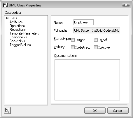
Attributes, operations, constraints, and other information pertaining to the class can be defined in the Properties window. Information is grouped in categories. For example, the Operations category allows the adding, removing, and moving of class methods. You can switch between categories of information in the Categories list box. The Employee class has four attributes and no operations.
Here are the steps to add attributes to the Employee class.
If not open, open the Properties for the Employee class shape.
Select the Attributes group in the Category list box. The Attributes pane will appear.
The first three attributes are First, Last, and Title. The names are entered in the Attribute column. The type for each of these attributes is C#::string.
Add Pay Scale as the final attribute. The type is decimal.
The Manager and Teller classes inherit the Employee class. As such, we do not have to replicate in the child classes the attributes inherited from the Employee base class. The Employee class has no methods to be inherited. Child classes refine the base class and therefore become specialty classes. As such, both the Manager and Teller classes add members that make them specialty classes. In the Class shape for child classes, only the unique attributes and operations should be added.
Here are the steps to add the Manager and Teller class shapes to the class diagram.
Drag two Class shapes from the UML Static Structure stencil onto the Visio document for the class diagram. Drag the shapes somewhere near the Employee class shape. Place the shapes below left and below right of the Employee class shape.
As demonstrated previously, open the Properties of the leftmost Class shape. Name the class Manager. Select the Operations group in the Categories list box. The Operations pane will appear. Enter WireMoney and RefundFees as the methods. Neither has parameters nor returns an explicit return type.
Open the Properties of the rightmost Class shape. Name the class Teller. Add the CustomerDeposit and CustomerWithdrawal operations to the class.
Classes can be related through inheritance, association, or composition. There is a shape for each of these relations in the UML Static Structure stencil. Inheritance is defined with the Generalization shape. If a base class is inherited by more than child class, use multiple Generalization shapes. You can create an association between two classes with the Binary Association shape. For composition, use the composition shape. Multiplicity defines the numeric relation between the two classes (class1 and class2) that comprise a composition. For example, a multiplicity of 1 to 1 means that there is exactly one class1 for each class2 in the binary association. An example of a 1 to 1 relationship would be a bank and bank president. The bank, which exists, has one—and only one—bank president. Another type of multiplicity is 1..n to *. This means that there is at least one class1, where for any class1 there is any number of class2. An example of 1..n to * would be bank branch and customers. There is at least one bank branch. Each bank branch could have any number of customers.
As mentioned previously, both Manager and Teller classes inherit the Employee class. In addition, the relationship between Manager to Teller is 1 to 1..*. Each bank manager can manage one or more tellers. Here are the steps to define the relationships among the Manager, Teller, and Employee classes.
Drag the Generalization shape from the UML Static Structure stencil onto the Visio document. Connect the arrow portion of the Generalization shape to the Employee shape. Connect the opposite end of the arrow shape to the Manager shape. When connected, the location of the connection is highlighted.
Drag another Generalization shape from the UML Static Structure stencil onto the Visio document. Connect the arrow portion of the Generalization shape to the same location on the Employee shape as chosen before. Connect the opposite end of the arrow shape to the Teller shape.
Drag a Binary Association shape from the UML Static Structure stencil into the drawing. Connect either end of the shape to the Manager and Teller shapes. Open the properties for the Binary Association shape by double-clicking on the Binary Association shape. Alternatively, open the Properties using the context menu for the Binary Association shape. In the Association Properties window, delete the end names, which are in the Association Ends List. See 2-9. Change the multiplicity to 1 to 1..* (many).

Retail banking customers have either a checking or savings account. The checking and savings accounts are related. They are both "is a" kind of bank accounts. In object-oriented programming, "is a" implies inheritance. In this circumstance, Account is a base class and holds the common members of the Checking and Savings classes. Both the Checking and Savings classes then inherit from the Account base class. For the purpose of this example, only the Account class is defined. Customers must have an Account class.
Here are the steps to create the Account and Customer classes.
Drag a Class shape from the UML Static Structure stencil onto the Visio document. As shown previously, open the Properties of the new Class shape. Name the class Account. Select the Operations group in the Categories list box. The Operations pane will appear. Enter Deposit and Withdrawal as the methods. The methods have no parameters nor return an explicit return type.
Select the Attributes group in the Category list box. The Attributes pane will appear. Enter First and Last as the names of the first two attributes. Both are C#::string type. Finally, enter an attribute named Transactions. For the purposes of this example, the type for this attribute remains undefined.
Drag a Class shape from the UML Static Structure stencil onto the Visio document. As shown previously, open the Properties window of the new Class shape. Name the class Customer. Select the Operations group in the Categories list box. The Operations pane will appear. Add the Deposit, Withdrawal, and WireMoney methods. The methods have neither parameters nor an explicit return type.
Select the Attributes group in the Category list box. The Attributes pane will appear. The first three attributes are First, Last, and SSN, which are entered in the Attribute column. The type for each is C#::string.
Tellers handle a single customer at a time, if any. This is a 1 to 0..1 relationship, where a teller can have zero or one customers. In addition, customers can have one or more accounts, such as checking and savings accounts. This implies composition between the Customer and Account classes and a 1 to 1..* relationship.
The Teller, Customer, and Account classes were created in the previous steps. Here are the steps to define the relationship among the Teller, Customer, and Account classes.
We need to create a relationship between the Teller and Customer classes. Drag a Composition shape from the UML Static Structure stencil onto the Visio document. Connect the arrow portion of the shape to the aggregator, which is the Teller class in this circumstance. Connect the other side of the shape to the Customer class. Open the properties for the Composition shape. Delete the end names. Define the multiplicity as 1 to 0..1.
Next define the relationship between the Customer and Account classes. Drag a Composition shape onto the drawing. Connect the arrow portion of the shape to the Customer class. Connect the other side of the shape to the Account class. Open the Properties for the Composition shape. Double-click the Composition shape to open the Properties window. Alternatively, open the Properties window using the context menu for the Composition association shape. Delete the end names. Define the multiplicity as 1 to 1..*.
Most of the class diagram, as shown previously in 2-3, has been completed. For practice, you might consider finishing the diagram. Once the modeling is completed, what is the next step? You might say, "at long last, coding!" Not actually. Before coding, there is one more step: prototyping.
Prototyping is an important phase of the software development life cycle and a conduit between product design and implementation. This conduit represents the transition from design to implementation or extensive coding. Prototyping is actually the first level of coding in the actual application but before detailed implementation. After the design work is complete, fight the proclivity to code now! Prototyping is an important validation of the design, a validation that is important before etching your design into concrete—better known as the implementation. Taking this intermediate step can help prevent having to take a jackhammer to your code later.
Prototyping, combined with instrumentation, can provide important conformation of application sequence, which is typically modeled in dynamic UML diagrams. This provides an important roadmap of application execution. Here is a promise: your application will probably not execute properly as long as the flow is invalid. Have you tried going somewhere without proper directions? Without the correct instructions, you will not get there, at least not without some luck. The proper execution of your program should not depend on luck. When possible, prototype the entire application and validate the flow before you begin implementing the first method. At this point, the implementation simply represents noise and can only detract form the ultimate goal. Remember, know where you are going before getting into the car and driving.
Use prototyping to validate the dynamic UML diagrams that you created, such as the sequence diagram. If this validation fails, there are two possibilities. First, the design is incorrect. Second, the prototype does not accurately reflect the modeling. In either circumstance, you are not properly prepared for implementation. Review the design diagrams in relation to the prototype to confirm where changes are necessary. This is an iterative process: design, prototype, validate, revisit design, revisit prototype, validate again, and so on.
Once prototyping is completed and verified, congratulations! You are ready to begin serious coding. In this order, implement a method, the methods of a class, and finally all of the classes of a particular module. This will facilitate orderly testing. If classes have the proper level of isolation, you should be able to implement and test the application one class at a time. Isolation between classes is one of the tenants of object-oriented programming. Testing as each class is implemented helps wring dependencies out of the application design. Chapter 1 mentions correctly that coding should only proceed as fast as it can be tested and verified for accuracy. In addition, frequent testing at this level provides a barometer of the ongoing health of the application.
Here are specific steps to prototype and instrument an application.
First, define the class framework in the application code using the UML Class diagram. Make sure to include all the methods, while omitting properties or attributes. In addition, use sparse prototypes for the methods (no parameters or return type). Omitting extraneous information improves clarity and makes detecting the correct sequencing of operations more transparent and instrumentation easier. The details, such as the proper function prototype, can be added before implementation of the related class.
Create an external resource, such as a config file, to enable or disable instrumentation.
Choose a class to instrument. Instrument the methods minimally with Enter and Exist messages. Further instrumentation can be added based on the level of detail you want.
Test classes a class at a time. Afterward, regression test previous classes that were instrumented. This assures that subtle bugs have not been introduced that would affect previously tested code. Repeat the previous steps until the entire system has been instrumented.
Instrumentation is an important aspect of prototyping and is the tangible confirmation of the sequence of events in an application. Instrumentation is sending formatted messages to one or more targets. Each message reports an event or activity, or is informational. An event is a user-defined activity. An activity is a predefined event, such as a start or stop activity. Informational messages are general messages, such as reporting the parameters of a method. In a large software system, with several contributors, the result is often a blizzard of messages. This is where consistency of message format can help. Messages should be standardized to include a minimum set of fields: project name, team member, module, class.function, and source file. Other optional information that might be useful is a time stamp and the build number.
In .NET, instrumentation can be orchestrated using tracing. The Trace and TraceSource classes offer considerable flexibility for this purpose. We have come a long way since the printf command. If you are not familiar with printf, you are probably under 30 and do not own a C++ book.
Simple tracing is available with the Trace class. Most of the methods of the Trace class are implemented as static methods, which are called on the class. Alternatively, you can use the TraceSource class. The TraceSource class has additional functionality for advanced tracing, such as additional tracing levels and filtering. The Trace and TraceSource classes are discussed fully in Chapter 9. This chapter presents only enough information on tracing to demonstrate prototyping. The TraceSource class, not the Trace class, is used in this chapter. It is preferred because of added flexibility.
Both the Trace and TraceSource classes allow remote activation of tracing using a configuration file. You do not have to modify and rebuild the application to change the status of instrumentation. This avoids introducing inadvertently bugs just to enable or disable instrumentation. This also allows nondevelopers, such as architects and testers, to control instrumentation. This is particularly important because individuals in this role may not even have access to a compiler.
There are three levels of configuration files: application, public policy, and machine configuration file. In this chapter, we focus on the application configuration file. An application configuration file will allow you to control instrumentation of a specific application. Application configuration files are placed in the same directory of the assembly. The file name of the configuration file is name.extension.config. For example, myapp.exe.config is the configuration file for myapp.exe. This is discussed more broadly in Chapter 3.
Here is a sample configuration file that controls tracing.
<configuration>
  <system.diagnostics>
    <sources>
      <source name="myTraceSource"
        switchName="mySwitch">
        <listeners>
          <add name="console"
            type="System.Diagnostics.ConsoleTraceListener">
          </add>
           <remove name="Default"/>
        </listeners>
      </source>
    </sources>
    <switches>
     <add name="mySwitch" value="error"/>
   </switches>
 </system.diagnostics>
</configuration>
Tracing is defined within the system.diagnostics element. The name of a particular trace source is identified in the source element. The source name is used in application code to identify the corresponding trace source, which is provided in the constructor of the TraceSource class. Listeners are the target of tracing and defined within the listeners elements. Each listener is added with an Add element. You can have multiple simultaneous listeners, such as the console, file, eventlog, and so on. The Switches element contains the available switches, which are used to filter message sent to the listeners. Individual switches are added with an Add element. The value attribute of the Add element identifies the type of switch.
Here is sample code that uses the preceding configuration file.
using System;
using System.Collections.Generic;
using System.Linq;
using System.Diagnostics;
namespace ConsoleApplication {
    class Program {
        private static TraceSource mySource =
            new TraceSource("myTraceSource");

        static void Main(string[] args){
            Activity1();
            mySource.Close();
            return;
        }
        static void Activity1(){
            mySource.TraceEvent(TraceEventType.Error, 1,
                "Error message.");
            mySource.TraceEvent(TraceEventType.Warning, 2,
                "Warning message.");
        }
    }
}
In the code, an instance of a TraceSource class is created. In the constructor, we associate this trace source with the one in the configuration file (i.e., myTraceSource). The new trace source will then inherit the settings from the configuration file, such as displaying to the console window as a listener. The two TraceSource.TraceEvent commands trace to this listener. The ultimate status of the messages is controlled by the trace switch settings in the configuration file. An error and warning messages are sent. However, only the error message is displayed. The warning message is filtered per the switch in the configuration file. Change the value of the switch in the configuration file from error to warning. Now both the warning and error messages are displayed. This change can be made without having to recompile the application, which is one of the benefits of using the TraceSource class and configuration file.
A picture is worth a thousand words. For the Visual Studio Class Designer, instead of words, we are referring to lines of code. The Class Designer is a depiction of a UML class diagram. You can quickly and easily convey some of the concepts of a class diagram, such as class relationships and membership. Complex concepts, such as composition, can be easily rendered in a visual chart. Like a UML diagram, the primary components of the Class Designer are classifiers, such as classes, structures, interfaces, delegates, and enums. You can forward engineer from the Class Designer and convert classifiers from visual representations into code. You can also reverse engineer from code to a Visual Studio class diagram. A class diagram is a Class Designer document.
The Class Designer is excellent for rapid prototyping. There are convenient steps for creating stubs for methods and properties. Beyond creating stubs, the class diagram is automatically synchronized to the project code. Changes to the class diagram are instantly reflected in the code and vice versa. Add a method to a class in the class diagram, and simultaneously a method is added to the same class in the project. Delete an attribute from an interface in the source code, and the associated attribute is removed from the related interface in the class diagram. This synchronization highlights one of the other benefits of the Class Designer, which is refactoring. You can visually and easily refactor an application, including renaming variables, changing accessibility, changing attribute type, updating function prototypes, and more.
After prototyping the software system using the Visual Studio Class Designer, you can easily instrument the resulting code. You can even create a snippet that will automatically insert the appropriate tracing commands for each operation.
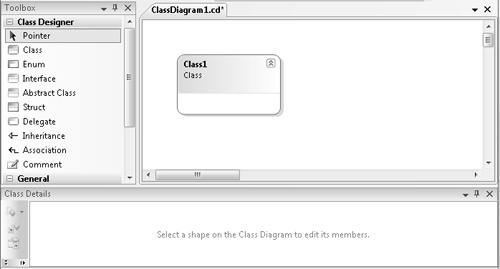
There are three important components to the Visual Studio Class Designer: the class diagram, Class Designer toolbox, and Class Details window. As mentioned earlier, a class diagram is an instance of a Class Designer document. The Class Designer toolbox contains shapes that are used to complete the class diagram. Finally, the Class Details window allows you to add, view, and edit members of classes, structs, and interfaces. 2-10 shows the Class Designer environment.
There are several ways to add a class diagram to a Visual Studio project:
From the Project menu, choose Add New Item. Select Class Diagram from the list of templates. You can then name the class diagram.
Alternatively, open the context menu for the project in Solution Explorer. Choose Add and then New Item. Select Class Diagram from the list of templates.
If this is the first class diagram of the project, you can simply open the context menu for the project in Solution Explorer and choose View Class Diagram.
You can then build the class diagram using drag and drop from the Class Designer toolbox. Drag shapes from the Class Designer toolbox onto the class diagram document. The toolbox includes all the requisite classifiers: class, struct, interface, enum, and delegate.
When you drop a classifier shape on the class diagram, the New dialog box will be presented. In the New dialog box, name the classifier, accessibility, and the file to place the entity. The shape is then added to the class diagram.
After adding a shape, you might also want to edit a particular shape. To modify a shape on the class diagram, first select the shape. A selected shape is highlighted with handles. Edit the shape from the Class Diagram menu. You can also use the context menu to add a member or edit the shape in some other manner. For example, to add a method to a class shape from the Class Diagram menu, select Add and then Method. You can then name the new method. In the Class Details window, define the prototype of the method by entering the return type and parameters. Expand the method row for the class in the Class Details window to view or add parameters. You can also add methods, properties, and attributes directly in the Class Details window instead of using the menu system.
Prototyping with the Class Designer is easy. Why? It is automatic. Add an operation to a class or struct and the stub is automatically created. You can then instrument the operation with an Enter and Exit message. Even the Enter and Exit methods can be automated in Visual Studio using code snippets. Code snippets are reusable snippets of code. Snippets can be parameterized to allow customization whenever the snippet is used. This adds considerable flexibility.
I have created two snippets that can be used to instrument an operation. The first code snippet creates an instance of the TraceSource class to be used for instrumentation. The TraceSource is appropriately named Instrumentation. It is a static attribute of a wrapper class called Instrument. You insert this snippet once into the application. That will make the TraceSource instance available everywhere as Instrument.ts. Here is the snippet.
<CodeSnippet Format="1.0.0">
  <Header>
    <Title>
      Instrument TraceSource
    </Title>
  </Header>

  <Snippet>
    <Code Language="CSharp">
      <![CDATA[class Instrument
      {
          public static System.Diagnostics.TraceSource ts =
              new System.Diagnostics.TraceSource("Instrumentation");

       }]]>
     </Code>
  </Snippet>

</CodeSnippet>
The second code snippet inserts code that uses the trace source instance defined in the first snippet (Instrument.ts) to display Enter and Exit messages for a stubbed method. Insert this snippet in each method to be instrumented. It adds two TraceEvent commands to the code. This code snippet has parameters (literals) for assigning the appropriate class and function name. Here is the second snippet.
<CodeSnippet Format="1.0.0">
  <Header>
    <Title>
      Instrumentation Enter Exit
    </Title>
  </Header>

  <Snippet>
    <Declarations>
      <Literal>
        <ID>Class</ID>
        <ToolTip>Name of surrounding class</ToolTip>
      </Literal>
      <Literal>
        <ID>Function</ID>
        <ToolTip>Function to instrument</ToolTip>
      </Literal>

    </Declarations>

    <Code Language="CSharp">
      <![CDATA[Instrument.ts.TraceEvent(System.Diagnostics.TraceEventType.Start, 1,
          "Entering $Class$.$Function$");

    // Insert code here

    Instrument.ts.TraceEvent(System.Diagnostics.TraceEventType.Stop, 2,
            "Leaving $Class$.$Function$");]]>
   </Code>
  </Snippet>

</CodeSnippet>
The messages from this snippet are sent to listeners defined in an application configuration file. You can send the messages to the console, text file, or any other listener you designate.
This walkthrough demonstrates prototyping and the instrumenting of code using Visual Studio. We will convert part of the UML Class Diagram for the retail banking system (see 2-3, shown previously) to a Visual Studio Class Diagram. Afterward, the class operations will be prototyped and instrumented. Because the intent is to validate the sequence diagram, we will omit attribute and other extraneous information. The aforementioned snippets for instrumentation will be used to instrument the methods of the application. Therefore, you must create and import the snippets before the walkthrough. Steps for importing a snippet can be found online at MSDN. Search for articles on code snippets. The walkthrough uses a console project.
Here are the steps to add a new class diagram to the project. A shape is then added to the diagram.
First, review the UML class diagram related to the retail banking system.
In Solution Explorer, open a context menu. Choose Add and then New Item. Choose Class Diagram from the list of templates. Name the class diagram Bank.cd.
From the Class Designer toolbox, drag a class shape onto the class diagram. In the New Class dialog box, name the class Customer. Accept the defaults for everything else.
Add a method to the class. Open the context menu for the Customer class shape. Choose Add and then Method. Name the method Deposit. Repeat these steps, and add the Withdrawal and WireMoney methods. This will also automatically add stubbed functions for Deposit, Withdrawal, and WireMoney to the source files. Do not add parameters or return types for any of the methods. They are not necessary at this time.
Add the Employee, Manager, and Teller classes to the class diagram. Employee is the base class to the Manager and Teller classes. Here are the steps.
Add a class shape to the class diagram. Name the class Employee. Employee is an abstract type, while Manager and Teller are concrete. Open the context menu for the Employee shape. Choose Properties. From the Properties window, choose the Inheritance Modifier field. Change the field to abstract. Place the Employee class in Employee.cs.
Add the Manager and Teller classes to the class diagram. Drag two classes onto the class diagram. Using steps shown previously, name the classes Manager and Teller. Place both class implementations in Employee.cs. Add the WireMoney and RefundFees methods to the Manager class. For the Teller class, add the CustomerDeposit and CustomerWithdrawal methods.
Have the Manager class inherit from the Employee base class. Select the inheritance shape in the Class Designer toolbox. Drag from the Manager to the Employee class. An inheritance will appear that connects the two classes. Repeat the previous steps for the Teller child class. The Teller class also inherits from the Employee base class.
There is 1 to 1 multiplicity between the Teller and Customer classes. Click the Association shape in the Class Designer toolbox. Click and drag from the Teller class to the Customer class. This will draw the association line and connect the two classes.
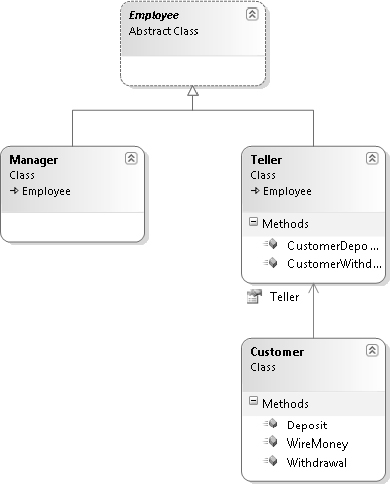
2-11 shows the Visual Studio class diagram for the retail banking system.
The function prototypes already exist. This occurred when the methods were added to the class diagram. The next step is to instrument the functions. First, we must create the TraceSource object to be used. This can be done with the snippet provided earlier. Here are the steps:
Insert a new source file: instrument.cs. Delete the sample class that is automatically inserted into the file.
Make sure the cursor is within the namespace in the instrument.cs file. Insert the Instrument TraceSource snippet. Pressing Ctrl+K and then Ctrl+X will prompt for the snippet. You can then locate and insert the Instrument TraceSource snippet. The keystrokes for inserting a snippet can vary depending on your keyboard configuration in Visual Studio.
The trace source is controlled from an application configuration file. In our example, tracing should be sent to a console window. We also want to display all activity tracing, which includes the Start and Stop events used in the instrumenting of the methods. Here is the application configuration file:
<configuration>
  <system.diagnostics>
    <sources>
      <source name="Instrumentation"
        switchName="sourceSwitch">
        <listeners>
          <add name="console"
            type="System.Diagnostics.ConsoleTraceListener">
          </add>
           <remove name="Default"/>
        </listeners>
      </source>
    </sources>
    <switches>
      <add name="sourceSwitch" value="ActivityTracing"/>
    </switches>
  </system.diagnostics>
</configuration>
So far, we have created the class diagram, prototyped the methods, defined an instance of the TraceSource class, and added an application configuration file. You are ready for the last step. That step is to instrument the methods of each class. A snippet is used to instrument the Enter and Exit events of a method.
Open the Customer.cs file. Review the stubbed methods. Each of the stubbed methods explicitly throws an exception. Select the exception statement in the Deposit method and insert the Instrument Enter Exit snippet. Pressing Ctrl+K and then Ctrl+X will prompt for the snippet. Locate and insert the snippet. Two literal fields are presented in the snippet. Fill the literal fields with the class and method names respectively. You can tab between the fields.
Repeat the previous step to instrument the Customer.Withdrawal and Customer. WireMoney methods. While in the Customer.cs file, remove the exception from the Customer constructor class.
Open the employee.cs file. Instrument the Teller.CustomerWithdrawal and Teller. CustomerDeposit methods as shown previously using the Instrument Enter Exit snippet.
According to the class diagram, there is a relationship between the Customer and Teller classes. For this reason, the Teller class is embedded in the Customer class. The Teller class is exposed as a property of the Teller class. In the Customer class, you need to update the Teller property to use automatic Get and Set functions, as shown in the following code.
public Teller Teller
{
    get; set;
}
According to the sequence diagram, the Customer.Withdrawal method calls Teller. CustomerWithdrawal, while Customer.Deposit calls Teller.CustomerDeposit. The prototype should confirm this sequence. In Main, the code is written to test this sequence.
static void Main(string[] args)
{
    Customer cust = new Customer();
    cust.Teller = new Teller();
    cust.Deposit();
    cust.Withdrawal();
}
Run the program, and view results. Congratulations! You have validated the sequence diagram. There were a few steps to accomplish this. Of course, this is a simple example. The more complex the application, the greater the return on investment. You are ready to begin full coding.