

Environmentals
This chapter describes the environmental requirements for IBM z15TM servers. It also lists the dimensions, weights, power, and cooling requirements that are needed to plan for the installation of an z15 server.
|
Naming: Throughout this chapter, z15 refers to IBM z15 Model T01 (Machine Type 8561), unless otherwise specified.
|
The following options are available for physically installing the server:
•Air or water cooling
•Power Distribution Unit (PDU) or Bulk Power Assembly (BPA) for power
•Installation on a raised floor or non-raised floor
•I/O and power cables can exit under the raised floor or off the top of the server frames
For more information about physical planning, see IBM Z 8561 Installation Manual for Physical Planning, GC28-7002.
This chapter includes the following topics:
11.1 Power and Cooling
The z15 server can be a 1 - 4 19-inch rack system, depending on the configuration. Frames are shipped separately in Arbo crates, along with separate front and rear cover sets for each frame boxed on a shipping pallet. The frames are bolted together during the installation procedure. z15 servers support installation on a raised floor or non-raised floor.
The z15 servers are available in the following power and cooling options:
•Intelligent Power Distribution Unit-based power (iPDU) - or PDU
Radiator-based cooling (air cooled system)
•Bulk Power Assembly-based power (BPA):
– Radiator-based cooling (air cooled system)
– Water Cooling Unit that uses customer-provided chilled water supply
11.1.1 Intelligent Power Distribution Unit (iPDU)
The iPDUs can be ordered as the following feature codes, per client datacenter power infrastructure requirements:
•60A / 3 Phase “Delta” PDU feature code (FC 0629)
•60A / 3 Phase “Wye” PDU feature code (FC 0630)
A PDU-based system can have 2 - 8 power cords, depending on the configuration. The use of iPDU on z15 might enable fewer frames, which allows for more I/O slots to be available and improves power efficiency to lower overall energy costs. It also offers some standardization and ease of data center installation planning, which allows the z15 to easily coexist with other platforms within the data center.
Power requirements
The z15 is designed with a fully redundant power system. To make full use of the redundancy that is built into the server, the PDUs within one pair must be powered from different power distribution panels. In that case, if one PDU in a pair fails, the second PDU ensures continued operation of the server without interruption.
The second, third, and fourth PDU pairs are installed dependent on other CPC or PCIe+ I/O drawers installed. The locations of the PDU pairs and frames are listed in Table 11-1.
Table 11-1 PDU pairs and frames location
|
Frame C
|
Frame B
|
Frame A
|
|
N/A
|
N/A
|
PDU A3 / A4
|
|
PDU C1 / C2
|
PDU B1 / B2
|
PDU A1 / A2
|
Power cords for the PDUs are attached to the options that are listed in Table 11-2.
Table 11-2 Power cords for PDUs
|
Supply type
|
Input voltage
|
Input frequency
|
Input current rating
|
|
2, 4, 6, or 8, 3-phase power cords
|
200 - 240 V AC
|
50/60 Hz (47 - 63 Hz with tolerance)
|
48 A
|
|
2, 4, 6, or 8, 3-phase power cords
|
380 - 415 V AC
|
50/60 Hz (47 - 63 Hz with tolerance)
|
24 A
|
A rear view of a maximum configured PDU-powered system with five CPC drawers and 12 PCIe+ I/O drawers is shown in Figure 11-1.
:
Figure 11-1 Rear View of maximum configured PDU system
The number of PDUs and power cords that are required based on the number of CPC drawers and PCIe+ I/O drawers are in Table 11-3.
Table 11-3 Number of PDUs installed
|
Number of
CPCs
|
Number of PCIe+ I/O drawers
|
||||||||||||
|
0
|
1
|
2
|
3
|
4
|
5
|
6
|
7
|
8
|
9
|
10
|
11
|
12
|
|
|
1
|
2
|
2
|
2
|
2
|
|
|
|
|
|
6
|
6
|
6
|
6
|
|
2
|
4
|
4
|
4
|
4
|
4
|
4
|
4
|
4
|
6
|
6
|
6
|
6
|
6
|
|
3
|
4
|
4
|
4
|
4
|
4
|
4
|
4
|
6
|
6
|
6
|
6
|
6
|
N/A
|
|
4
|
6
|
6
|
6
|
6
|
6
|
6
|
6
|
6
|
6
|
6
|
8
|
8
|
8
|
|
5
|
6
|
6
|
6
|
6
|
6
|
6
|
6
|
6
|
6
|
8
|
8
|
8
|
8
|
Power consumption
The utility power consumption for the z15 for PDU option is listed in Table 11-4.
Table 11-4 z15 utility power consumption for PDU
|
FC CPC #
|
Number of PCIe+ I/O drawers
|
||||||||||||
|
0
|
1
|
2
|
3
|
4
|
5
|
6
|
7
|
8
|
9
|
10
|
11
|
12
|
|
|
max34
FC0655
|
3.8
kw
|
4.8
kw
|
5.9
kw
|
6.9
kw
|
8.0
kw
|
9.0
kw
|
10.0
kw
|
11.1
kw
|
12.1
kw
|
13.2
kw
|
14.2
kw
|
15.3
kw
|
16.1
kw
|
|
max71
FC0656
|
6.9
kw
|
7.9
kw
|
9.0
kw
|
10.0
kw
|
11.1
kw
|
12.1
kw
|
13.2
kw
|
14.2
kw
|
15.3
kw
|
16.3
kw
|
17.4
kw
|
18.4
kw
|
19.2
kw
|
|
max108
FC0657
|
10.1
kw
|
11.1
kw
|
12.2
kw
|
13.2
kw
|
14.3
kw
|
15.3kw
|
16.4
kw
|
17.4
kw
|
18.5
kw
|
19.5
kw
|
20.6
kw
|
21.6kw
|
N/A
|
|
max145
FC0658
|
13.5
kw
|
14.5
kw
|
15.6
kw
|
16.6
kw
|
17.7
kw
|
18.7
kw
|
19.8
kw
|
20.8kw
|
21.9kw
|
22.9
kw
|
24.0kw
|
25.0kw
|
25.8kw
|
|
max190
FC0659
|
16.6
kw
|
17.6
kw
|
18.7
kw
|
19.7
kw
|
20.8
kw
|
21.8
kw
|
22.9
kw
|
23.9
kw
|
25.0kw
|
26.0
kw
|
27.1kw
|
28.1kw
|
28.9
kw
|
|
Note: Consider the following points:
•The power values that are listed in this table assume the CPC process drawer and PCIe+ I/O drawers are plugged to the maximum with highest power features (that is, memory and I/O adapters and fanouts). Also assumed is that maximum ambient temperature is used.
•Typical configurations and data center conditions result in lower power. A calculator available on Resource Link calculates power and weight for specific configurations and environmental conditions.
|
|||||||||||||
|
Considerations: Power consumption is lower in a normal ambient temperature room, and for configurations that feature a lesser number of I/O slots, smaller amount of memory, and fewer PUs.
Power estimation for any configuration, power source, and room condition can be obtained by using the power estimation tool that is available at the IBM Resource Link website (login required).
On the Resource Link page, click Tools → Power and weight estimation.
|
11.1.2 Bulk Power assembly (BPA)
The Bulk Power Assembly consists of the following features:
•BPA (FC 0640)
•Balanced Power Plan ahead (FC 3003)
•Bulk Power Regulator (BPR) (FC 3016)
•Internal Battery Feature (FC 3217)
The BPA option is required for clients who order an Internal Battery Feature (IBF), Water Cooling Unit (WCU), or Balanced Power. The BPA requires two or four power cords. All BPAs are concurrently repairable in the field.
Power requirements
The 8561 operates from 2 or 4 fully redundant power supplies. These redundant power supplies each have their own power cords, or pair of power cords, which allows the system to survive the loss of customer power to either power cord or power cord pair.
If power is interrupted to one of the power supplies, the other power supply assumes the entire load and the system continues to operate without interruption. Therefore, the power cords for each power supply must be wired to support the entire power load of the system.
For the most reliable availability, the power cords in the rear of the frame should be powered from different PDUs. All power cords exit through the rear of the frame. The utility current distribution across the phase conductors (phase current balance) depends on the system configuration. Each front end power supply is provided with phase switching redundancy.
The loss of an input phase is detected and the total input current is switched to the remaining phase pair without any power interruption. Depending on the configuration input power draw, the system can run from several minutes to indefinitely in this condition. Because most single phase losses are transients that recover in seconds, this redundancy provides protection against virtually all single phase outages.
Power cords for the BPAs are attached to the options that are listed in Table 11-5.
Table 11-5 Power cords for the BPAs
|
Supply type
|
Nominal voltage range
|
Voltage tolerance
|
Frequency range
|
|
Two or four redundant 3-phase power cords
|
200 - 480 V AC
|
180 - 508 V AC
|
50 / 60 Hz
|
The source power cords ratings for BPA systems are listed in Table 11-6.
Table 11-6 Source power cords for BPA
|
Source type
|
Frequency
|
Input voltage range
|
Rated input current
|
|
Three-phase (60A plug)
|
50 / 60 Hz
|
200 V1
|
50 A
|
|
Three-phase (60A plug)
|
50 / 60 Hz
|
208 - 240 V2
|
48 A
|
|
Three-phase (30A plug)
|
50 / 60 Hz
|
380 V - 415 V3
|
24 A
|
|
Three-phase (30A plug)
|
60 Hz
|
480 V4
|
20 A
|
|
Three-phase (63A no plug)
|
50 / 60 Hz
|
220 V - 480 V
|
48 A
|
|
Three-phase (32A no plug)
|
50 / 60 Hz
|
380 V - 415 V
|
25 A
|
1 Japan (same physical cord as Note b)
2 US, Canada (same physical cord as Note a)
3 US, Canada only
4 US only
A rear view of a maximum configured BPA powered system with two BPA pairs, IBF, five CPC drawers, and 11 PCIe+ I/O drawers is shown in Figure 11-2.

Figure 11-2 Rear view of maximum configured BPA system
The number of power cords that are required based on the number of CPC drawers and PCIe+ I/O drawers are listed in Table 11-7.
Table 11-7 Number of power cords installed
|
Number of
CPCs
|
Number of PCIe+ I/O drawers
|
|||||||||||
|
0
|
1
|
2
|
3
|
4
|
5
|
6
|
7
|
8
|
9
|
10
|
11
|
|
|
1
|
1
|
1
|
2
|
2
|
2
|
2
|
2
|
3
|
3
|
3
|
4
|
4
|
|
2
|
1
|
2
|
2
|
2
|
2
|
2
|
3
|
3
|
3
|
4
|
4
|
4
|
|
3
|
1
|
2
|
2
|
2
|
2
|
2
|
3
|
3
|
3
|
4
|
4
|
4
|
|
4
|
2
|
2
|
3
|
3
|
3
|
3
|
3
|
4
|
4
|
4
|
4
|
4
|
|
5
|
2
|
2
|
3
|
3
|
3
|
3
|
3
|
4
|
4
|
4
|
4
|
4
|
The number of power cords and number of Bulk Power Regulators required based on the number of CPC processor drawers and number of PCIe+ I/O drawers in the configuration (radiator or WCU) is shown in Table 11-8 on page 457.
Table 11-8 Number of BPRs installed per BPA
|
|
Number of PCIe+ I/O drawers
|
||||||
|
0
|
1
|
2
|
3
|
4
|
5
|
6
|
|
|
1 CPC
|
1
|
1
|
2
|
2
|
2
|
2
|
2
|
|
2 CPC
|
2
|
2
|
2
|
2
|
2
|
3
|
3
|
|
3 CPC
|
2
|
2
|
3
|
3
|
3
|
3
|
-
|
|
Note: Balanced power feature includes all BPRs that are plugged in all BPAs in the system.
|
|||||||
Power consumption
The utility power consumption for the z15 for the BPA radiator cooled system option is listed in Table 11-9.
Table 11-9 Utility Power consumption (BPA) for radiator-cooled systems
|
CPC Feature Code
|
Number of PCIe+ I/O drawers
|
|||||||||||
|
0
|
1
|
2
|
3
|
4
|
5
|
6
|
7
|
8
|
9
|
10
|
11
|
|
|
max34
FC0655
(1)
|
4.2
kw
|
5.3
kw
|
6.4
kw
|
7.5
kw
|
8.6
kw
|
9.7
kw
|
10.9
kw
|
12.0
kw
|
13.1
kw
|
14.2
kw
|
15.3
kw
|
16.4
kw
|
|
max71
FC0656
(2)
|
7.5
kw
|
8.6
kw
|
9.7
kw
|
10.8
kw
|
11.9
kw
|
13.0
kw
|
14.2
kw
|
15.3
kw
|
16.4
kw
|
17.5
kw
|
18.6
kw
|
18.6
kw
|
|
max108
FC0657
(3)
|
10.9
kw
|
12.0
kw
|
13.1
kw
|
14.2
kw
|
15.3
kw
|
16.4
kw
|
17.6
kw
|
18.7
kw
|
19.8
kw
|
20.9
kw
|
22.0
kw
|
22.0
kw
|
|
max145
FC0658
(4)
|
14.8
kw
|
15.9
kw
|
17.0
kw
|
18.1
kw
|
19.2
kw
|
20.3
kw
|
21.4
kw
|
22.5
kw
|
23.6
kw
|
24.8
kw
|
25.9
kw
|
25.9
kw
|
|
max190
FC0659
(5)
|
18.1
kw
|
19.2
kw
|
20.3
kw
|
21.4
kw
|
22.5
kw
|
23.6
kw
|
24.7
kw
|
25.8
kw
|
26.9
kw
|
28.0
kw
|
29.2
kw
|
29.2
kw
|
|
Note: Consider the following points:
•The power values that are listed in this table assume the CPC process drawer and PCIe+ I/O drawers are plugged to the maximum with highest power features (that is, memory and I/O adapters and fanouts). Also assumed is that maximum ambient temperature is used.
•Typical configurations and data center conditions result in lower power. A calculator that is available on Resource Link calculates power and weight for specific configurations and environmental conditions.
|
||||||||||||
The utility power consumption for the z15 for the BPA water-cooled system option is listed in Table 11-10.
Table 11-10 Utility Power consumption (BPA) for water-cooled systems
|
CPC Feature Code
|
Number of PCIe+ I/O drawers
|
|||||||||||
|
0
|
1
|
2
|
3
|
4
|
5
|
6
|
7
|
8
|
9
|
10
|
11
|
|
|
max34
FC0655
(1)
|
4.0
kw
|
5.1
kw
|
6.2
kw
|
7.3
kw
|
8.4
kw
|
9.5
kw
|
10.6
kw
|
11.8kw
|
12.9
kw
|
14.0
kw
|
15.1
kw
|
16.2
kw
|
|
max71
FC0656
(2)
|
7.2
kw
|
8.3
kw
|
9.4
kw
|
10.5
kw
|
11.6
kw
|
12.7
kw
|
13.8
kw
|
14.9
kw
|
16.1
kw
|
17.2
kw
|
18.3
kw
|
19.4
kw
|
|
max108
FC0657
(3)
|
10.4
kw
|
11.5
kw
|
12.6
kw
|
13.7
kw
|
14.8
kw
|
15.9
kw
|
17.0
kw
|
18.1
kw
|
19.2
kw
|
20.4
kw
|
21.5
kw
|
22.6
kw
|
|
max145
FC0658
(4)
|
14.0
kw
|
15.1
kw
|
16.2
kw
|
17.3
kw
|
18.5
kw
|
19.6
kw
|
20.7
kw
|
21.8
kw
|
22.9
kw
|
24.0
kw
|
25.1
kw
|
26.2
kw
|
|
max190
FC0659
(5)
|
17.2
kw
|
18.3
kw
|
19.4
kw
|
20.5
kw
|
21.6
kw
|
22.8
kw
|
23.9
kw
|
25.0
kw
|
26.1
kw
|
27.2
kw
|
28.3
kw
|
29.4
kw
|
|
Notes: Consider the following points:
•The power values that are listed in this table assume the CPC process drawer and PCIe+ I/O drawers are plugged to the maximum with highest power features (that is, memory and I/O adapters and fanouts). Also assumed is that maximum ambient temperature is used.
•Typical configurations and data center conditions result in lower power. A calculator that is available on Resource Link calculates power and weight for specific configurations and environmental conditions.
|
||||||||||||
Balanced Power Plan Ahead feature
Phase currents are minimized when they are balanced among the three input phases. Balanced Power Plan Ahead (FC 3003) is designed to allow you to order the full complement of bulk power regulators (BPRs) on any configuration to help ensure that the configuration is in a balanced power environment
If the z15 server is configured with the Internal Battery Feature (IBF), Balanced Power Plan Ahead automatically supplies the maximum number of batteries (IBFs) with the system.
|
Consideration: Power consumption is lower when in a normal ambient temperature room, and for configurations that feature a lesser number of I/O slots, smaller amount of memory, and fewer processors. Power consumption is also slightly lower for DC input voltage. The numbers that are listed in this section assume that batteries are present and charging.
Power estimation for any configuration, power source, and room condition can be obtained by using the power estimation tool at IBM Resource Link website (authentication required).
On the Resource Link page, click Tools → Power and weight estimation.
|
11.1.3 Cooling requirements
The z15 cooling system includes with two options: Radiator (air) cooled or water-cooled system. Single chip modules (SCMs) are always cooled with an internal water loop, no matter which z15 cooling option is chosen. The liquid in the internal water circuit can be cooled by using a radiator (for air-cooling option) or customer-supplied chilled water supply (for water-cooling option). I/O drawers, PCIe I/O drawers, power enclosures, and CPC drawers are cooled by chilled air with blowers.
The z15 servers include a recommended (long-term) ambient temperature range of 18°C (64.4°F) - 27°C (80.6°F). The minimum allowed ambient temperature is 5°C (41°F) and the maximum allowed temperature is 40°C (104°F).
For more information about cooling requirements, see IBM Z 8561 Installation Manual for Physical Planning, GC28-7002.
Radiator (air) cooling
The following radiator (air) cooling options are available:
•A-Frame radiator air-cooled feature code (FC 4033)
•B-Frame radiator air-cooled feature code (FC 4035)
The radiator cooling system requires chilled air to fulfill the air-cooling requirements. z15 system airflow is from the front (intake, chilled air) to the rear (exhausts, warm air) of the frames. The chilled air is provided through perforated floor panels in front of the system
The hot and cold airflow and the arrangement of server aisles are shown in Figure 11-3.

Figure 11-3 Hot and cold aisles
As shown in Figure 11-3, rows of servers must be placed front-to-front. Chilled air is provided through perforated floor panels that are placed in rows between the fronts of servers (the cold aisles). Perforated tiles generally are not placed in the hot aisles. If your computer room causes the temperature in the hot aisles to exceed a comfortable temperature, add as many perforated tiles as necessary to create a satisfactory comfort level. Heated exhaust air exits the computer room above the computing equipment.
For more information about the requirements for air-cooling options, see IBM Z 8561 Installation Manual for Physical Planning, GC28-7002.
Water-cooled system requirements
The following water-cooled options are available:
•A-Frame water-cooled feature code (FC 4034)
•B-Frame water-cooled feature code (FC 4036)
The water cooled 8561 system requires four or eight connections to the facility water, depending on the system configuration. Consider the following points:
•Systems with 1 - 3 CPC drawers require two feeds and two returns in the rear of the A frame.
•Systems with more than three CPC drawers require two feeds and two returns in the rear for both the A and the B frames.
These connections are made by using hoses that are fixed to the facility plumbing. They are routed up through the rear tailgate of the machine and terminated by using quick connect couplings.
Hoses and a means to fasten them to the facility plumbing are provided with the server.
The water cooled 8561 systems with one to three CPC drawers feature one water cooling assembly (WCA). The water cooled 8561 systems with four or five CPC drawers include two WCAs. Each WCA contains two fully redundant water control units (WCUs). These water control units each have their own facility feed and return water connections. If water is interrupted to one of the WCUs, the other water control unit assumes the entire load and the server continues to operate without interruption.
Therefore, each water connection to the facility plumbing must support the entire flow requirement for the WCA. If water is lost to both WCUs, the system attempts to reject heat by using the inner door heat exchangers in each frame and increasing system blower speeds. The server can also run in a degraded mode during this event.
|
Raised floor: The minimum raised floor height for a water-cooled system is 22.86 cm
(8.6 in.). |
These connections are made by using hoses that are fixed to the facility plumbing and are routed up through the rear tailgate of the system. They end with quick connect couplings.
Before you install z15 servers with water-cooled option, your facility must meet following requirements:
•Total water hardness cannot exceed 200 mg/L of calcium carbonate.
•The facility water pH is 7 - 9.
•Turbidity is less than 10 Nephelometric Turbidity Units (NTUs).
•Bacteria is less than 1000 colony-forming units (CFUs)/ml.
•The water is as free of particulate matter as feasible.
•The allowable system inlet water temperature range is 6°C - 20°C (43°F - 68°F) by using standard building chilled water. A special water system is typically not required.
•The flow rate to the frame is 3.7 - 79.4 lpm (1 - 21 gpm), depending on the inlet water temperature and the number of processor drawers in the z13 server. Colder inlet water temperatures require less flow than warmer water temperatures. Fewer processor drawers require less flow than a maximum populated z13 server.
•The minimum water pressure across the IBM hose ends is 0.34 - 2.32 BAR (5 - 33.7 psi), depending on the minimum flow required.
The maximum water pressure that is supplied at the IBM hose connections to the client’s water supply cannot exceed 6.89 BAR (100 psi).
Supply hoses for the water-cooled systems
The z15 water-cooled system includes a customer “kit” that contains the hoses, clamps, and necessary fittings to install the supply and return hoses that connect to the WCUs in the system. Included are 4.2 m (13.7 ft) water hoses. The WCU water supply connections are shown Figure 11-4.

Figure 11-4 WCU water supply connections
The client’s ends of the hoses are left open, which allows you to cut the hose to a custom length. An insulation clamp is provided to secure the insulation and protective sleeving after you cut the hose to the correct length and install it onto your plumbing.
|
Important: Use shut-off valves in front of the hoses. This configuration allows for the removal of the hoses for a service procedure or relocation. Valves are not included in the order. A stainless steel fitting is available for ordering. The fitting is barbed on one side and has a 2.54 cm (1 in.) male national pipe thread (NPT).
For more information about the tools that are needed for the water supply connections, see IBM Z 8561 Installation Manual for Physical Planning, GC28-7002.
|
11.1.4 Internal Battery Feature
If a power shutdown occurs, the optional Internal Battery Feature (IBF) provides sustained system operations for a relatively short time, which allows a proper z15 server’s shutdown. In addition, an external uninterrupted power supply system can be connected, which allows for longer periods of sustained operation.
|
Attention: The optional Internal Battery Feature (FC 3217) contains lithium ion batteries, which are packaged separately from the frame. A pair of batteries weighs approximately 43.5 kg (96 lb), as each individual battery weighs approximately 21.8 kg (48 lb).
Because of the hazardous nature of these Lithium ion batteries, only a certified Dangerous Goods Transportation employee is authorized to package and ship the IBFs. In the event of a system relocation, this restriction must be considered and is the responsibility of the client.
For more information, see IBM Z 8561 Installation Manual for Physical Planning, GC28-7002.
|
The IBF (when installed) can provide emergency power for the estimated time that is listed in Table 11-11. The number of IBFs depends on the number of BPRs. For the number of BPRs that are installed in relation to I/O units and the number of CPC drawers, see Table 11-8 on page 457. They are installed in pairs. You can have two, four, or six batteries (odd numbers are not allowed) per BPA.
Table 11-11 Battery hold-up times (minutes) for IBM z15 Model T01
|
CPC
Feature
|
number of PCIe+ I/O drawers
|
|||||||||||
|
0
|
1
|
2
|
3
|
4
|
5
|
6
|
7
|
8
|
9
|
10
|
11
|
|
|
IBF hold-up time (minutes)
|
||||||||||||
|
Max34
FC 0655
|
10
|
7
|
12
|
10
|
9
|
8
|
7
|
7
|
7
|
7
|
7
|
7
|
|
Max71
FC 0656
|
11
|
9
|
8
|
7
|
6
|
9
|
9
|
9
|
9
|
9
|
9
|
9
|
|
Max108
FC 0657
|
7
|
6
|
9
|
8
|
8
|
7
|
7
|
7
|
7
|
7
|
7
|
7
|
|
Max145
FC 0658
|
7
|
7
|
6
|
8
|
8
|
7
|
7
|
7
|
7
|
7
|
7
|
7
|
|
Max190
FC 0659
|
7
|
7
|
6
|
9
|
8
|
8
|
7
|
7
|
7
|
7
|
7
|
7
|
|
Notes: Consider the following points:
•The numbers that are shown assume both BPAs feeding power with the batteries charged at full capacity
•Hold-up times are influenced by temperature, battery age, and fault conditions within the system.
|
||||||||||||
|
Consideration: The system holdup times that are listed in Table 11-11 on page 462 assume that both sides are functional and have fresh batteries under normal room ambient conditions.
Holdup times are greater for configurations that do not have every I/O slot plugged, the maximum installed memory, and are not using the maximum processors.
These holdup times are estimates. Your particular battery holdup time for any specific circumstance might be different.
Holdup times vary depending on the number of BPRs that are installed. As the number of BPRs increases, the holdup time also increases until the maximum number of BPRs is reached. After six BPRs (three per side) are installed, no other batteries are added; therefore, the time decreases from that point.
Holdup times for actual configurations are provided in the power estimation tool at IBM Resource Link website.
On the Resource Link page, click Tools → Machine information. Then, select your IBM Z system and click Power Estimation Tool.
|
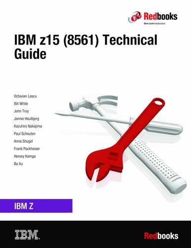
The BPR plugging order in the Bulk Power Enclosure is shown in Figure 11-5. Only the A frame is shown, but the same order is used in the B or C racks if present. Consider the following points:
•BPRs (and IBF units when the feature is installed) always are plugged in pairs.
•The number of IBFs (when installed) always equals the number of BPRs.
The plug order of BPRs is shown Figure 11-5.
Figure 11-5 BPR / IBF (when present) plugging order
11.2 Physical specifications
This section describes the weights and dimensions of z15 server. The z15 is the first IBM Z enterprise class server that is based on a 19-inch rack; therefore, dimensions and weights are significantly different from previous generations of IBM Z servers.
The z15 can be installed on a raised or non-raised floor. For more information about weight distribution and floor loading tables, see IBM 8561 Installation Manual for Physical Planning, GC28-7002. This data is used with the maximum frame weight, frame width, and frame depth to calculate the floor loading.
Weight estimates for the maximum system configurations on the 8561 are listed in Table 11-12.
Table 11-12 Weights for maximum machine configurations (PDU)
|
Frame
configurations
|
Individual frame weights
kg (lbs)
|
Total weight
kg (lbs)
|
|||
|
Z Frame
|
A Frame
|
B Frame
|
C Frame
|
||
|
A
|
-
|
795 kg
(1753 lbs)
|
-
|
-
|
795 kg
(1753 lbs)
|
|
ZA
|
711 kg
(1568) lbs
|
775 kg
(1709 lbs)
|
-
|
-
|
1486 kg
(3277 lbs)
|
|
ZAC
|
711 kg
(1568) lbs
|
756 kg
(1667 lbs)
|
-
|
740 kg
(1632 lbs)
|
2207 kg
(4866 lbs)
|
|
AB
|
-
|
775 kg
(1709 lbs)
|
725 kg
(1599 lbs)
|
-
|
1500 kg
(3308 lbs)
|
|
ZAB
|
711 kg
(1568) lbs
|
756 kg
(1667 lbs)
|
725 kg
(1599 lbs)
|
-
|
2192 kg (4833 lbs)
|
|
ZABC
|
711 kg
(1568) lbs
|
756 kg
(1667 lbs)
|
705 kg
(1555 lbs)
|
641 kg
(1413 lbs)
|
2813 kg
(6203 lbs)
|
|
Notes: Consider the following points:
•Weight is based on the maximum system configuration.
•All weights are approximate and do not include Earthquake Kit hardware.
•Be certain that the raised floor on which you are installing the server can support the weight.
|
|||||
The power and weight estimation tool for Z servers on Resource Link covers the estimated weight for your designated configuration. It is available on IBM Resource Link website.
On the Resource Link page, click Tools → Power and weight estimation.
11.3 Physical planning
This section describes the floor mounting, power, and I/O cabling options. For more information, see IBM 8561 Installation Manual for Physical Planning, GC28-7002.
11.3.1 Raised floor or non-raised floor
z15 servers can be installed on a raised or non-raised floor. The water-cooled models require a raised floor.
|
Note: On the z15, all I/O cabling and power cords come from the rear of the machine; therefore, all related features for Bottom and Top Exit cabling are in the rear of the frame.
|
Raised floor
If the z15 server is installed in a raised floor environment, air-cooled and water-cooled models are supported. You can select top exit features to manage I/O cables from the top frame of the z15 server.
The following top exit options are available for z15 servers:
•Top Exit I/O cabling feature code (FC 7917)
•Bottom Exit cabling feature code (FC 7919)
•Top Exit Cabling without Tophat feature code (FC 7928)
11.3.2 Top Exit cabling feature (optional)
The optional Top Exit cabling feature (FC 7917) allows for I/O cabling and power cords to exit the top of the frame. This feature adds cable management options, such as trunking and retainer brackets, as shown in Figure 11-6. The Top Exit cabling feature can be placed as shown in Figure 11-6, with the exit area towards the front of the frame, or with the exit area towards the rear of the frame.
|
Note: The feature provides the same extra hardware for every frame in the configuration.
|

Figure 11-6 Top Exit cabling feature
The Top Exit cabling feature adds 117.5 mm (4.63 in.) to the height of the frame and approximately 5.4 kg (12 lbs) to the weight.
If the Top Exit cabling feature is not ordered, two sliding plates are available on the top of the frame (one on each side of the rear of the frame) that can be partially opened. By opening these plates, I/O cabling and power cords can exit the frame. The plates should be removed to install the The Top Exit cabling feature as shown in Figure 11-7 on page 466.

Figure 11-7 Top Exit access plates
11.3.3 Top or bottom exit cables
Features allow for Top Exit Cabling (FC 7917) or Bottom Exit Cabling (FC 7919) cabling, or a combination of both. These features are independent of raised floor or non-raised floor installations and offer flexible possibilities for the data center.
All external cabling enters the rear of the rack from under floor or from above the rack. Different from previous Z Systems, no cabling access or cable plugging is available at the front of the rack. The top view of the rack with and without FC 7917 is shown in Figure 11-8.

Figure 11-8 With and without FC 7917
The Top Exit Cabling feature provides new hardware. The new hardware resembles a rectangular box with an open side that faces the front or rear of the rack. It includes other hardware to organize and fasten cables.
The Top Exit Cabling option can be used for routing power cables and IO cables out the top of the machine.
Without the Top Exit Cabling feature, power and cables still can be run out the top of the rack through two adjustable openings at the top rear of the rack, as shown on the left side of Figure 11-8.
The Bottom Exit Cabling feature provides tailgate hardware for routing power cables or IO cables out the bottom of the machine.
For more information, see IBM 8561 Installation Manual for Physical Planning, GC28-7002, and 11.3, “Physical planning” on page 464
11.3.4 Bottom Exit cabling feature
The Bottom Exit cabling feature (FC 7919) is required for raised floor environments, where I/O cabling or power cords must exit from the bottom of the frame. This feature includes the hardware to allow bottom exit, and other components for cable management and filler plates to preserve the recommended air circulation, as shown in Figure 11-9.

Figure 11-9 Bottom exit cabling feature
11.3.5 Frame Bolt-down kit
An Earthquake Kit, RF (FC 8010) is available for the z14 ZR1 servers. The kit provides hardware to enhance the ruggedness of the frame, the frame stiffener, and to tie down the frame to a concrete floor.
The frame tie-down kit can be used on a non-raised floor where the frame is secured directly to a concrete floor, or on a raised floor where the frame is secured to the concrete floor underneath the raised floor. Raised floors 241.3 mm (9.5 inches) - 1270 mm (50 inches) are supported.
The kits help secure the frames and their contents from damage when they are exposed to shocks and vibrations, such as in a seismic event. The frame tie-downs are intended for securing a frame that weighs up to 1308 kg (2885 lbs).
For more information, see IBM 8561 Installation Manual for Physical Planning, GC28-7002.
11.3.6 Service clearance areas
z15 servers require specific service clearance (see Figure 11-10 on page 468) to ensure the fastest possible repair in the unlikely event that a part must be replaced. Failure to provide enough clearance to open the front and rear covers results in extended service times or outages.
For more information, see IBM 8561 Installation Manual for Physical Planning, GC28-7002.

Figure 11-10 Maximum service clearance area (four frames)
11.4 Energy management
This section describes the elements of energy management to help you understand the requirements for power and cooling, monitoring and trending, and reducing power consumption. The energy management structure for the server is shown in Figure 11-11.

Figure 11-11 z15 Energy Management
The hardware components in the z15 server are monitored and managed by the energy management component in the Support Element (SE) and HMC. The graphical user interfaces (GUIs) of the SE and HMC provide views, such as the Monitors Dashboard, Environmental Efficiency Statistics, and Energy Optimization Advisor.
The following tools are available to plan and monitor the energy consumption of z15 servers:
•Power estimation tool on Resource Link
•Energy Optimization Advisor task for maximum potential power on HMC and SE
•Monitors Dashboard and Environmental Efficiency Statistics tasks on HMC and SE
11.4.1 Environmental monitoring
This section describes energy monitoring HMC and SE tasks.
Energy Optimization Advisor
This window is started from the HMC targeting the system and task under Energy Management. The window displays the following recommendations:
•Thermal Advice
•Processor Utilization Advice
Select the advice hyperlinks to provide specific recommendations for your system, as shown in Figure 11-12.

Figure 11-12 Energy Optimization Advisor
Monitors Dashboard task
In z15 servers, the Monitors Dashboard task in the Monitor task group provides a tree-based view of resources. Multiple graphical views display data, including history charts. This task monitors processor and channel usage. It produces data that includes power monitoring information, power consumption, and the air input temperature for the server.
An example of the Monitors Dashboard task is shown in Figure 11-13.

Figure 11-13 Monitors Dashboard task
Environmental Efficiency Statistics task
The Environmental Efficiency Statistics task (see Figure 11-14) is part of the Monitor task group. It provides historical power consumption and thermal information for the CPC.
The data is presented in table format and graphical “histogram” format. The data can also be exported to a .csv-formatted file so that the data can be imported into a spreadsheet. For this task, you must use a web browser to connect to an HMC.

Figure 11-14 Environmental Efficiency Statistics task
..................Content has been hidden....................
You can't read the all page of ebook, please click here login for view all page.