INSIDER’S GUIDE TO MIXED SIGNAL TEST
1.3. What Is a Mixed Signal Device?
1.5. Example of Mixed Signal Devices
1.6. Automatic Test Equipment (ATE)
1.7. Comparing Logic Test and Mixed Signal Test
1.8. More about the Signal Source
1.9. Mixed Signal Test System—Signal Capture
1.10. Mixed Signal Test System—Signal Analysis Chapter Review Questions
Hi. My name’s Mark Baker, and I’ve been working in and around mixed signal test for longer than I’d like to remember. After I’d been presenting seminars about mixed signal test for a few years, people said I should write a book. So here it is, and I hope you like it.
A while back, I caught up with my brother Len at some airport, somewhere. Len’s a banker, and when I gave him my business card, he looked it over and laughed, “Mixed Signal? What the heck is mixed signal? It sounds like the messages I get from my ex-wife!” Fortunately, the kind of mixed signal we’re talking about here has to do with electronics, a heck of a lot simpler subject than that other kind of mixed signal.
1.1 What Is Mixed Signal?
My favorite illustration of mixed signal technology is a music CD, which used to be known as a “Compact Digital disc.” The optically encoded information is digital data—ones and zeroes—but there is not an op-code or an address fetch to be found. Even more remarkable, when you put this Compact Digital disc into a CD player, music comes out. In this example of mixed signal, analog information is processed in digital form.
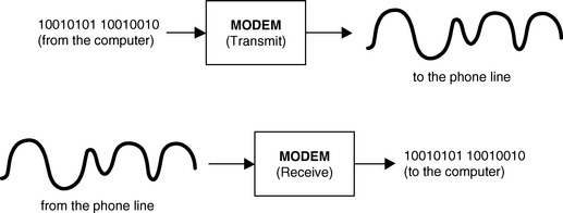
A modem is another common technology that illustrates mixed signal technology. If you’ve ever listened in on those awful squeaks and squawks that come out of a modem, you know there’s something strange going on. A modem interfaces between an analog system (the phone line) and a digital system (the data you are transmitting from your computer). In the case of a modem, digital information is processed in analog form.
These two simple illustrations of a music CD and a modem lead to a general definition of mixed signal technology: A mixed signal system (or component)
• processes analog information in digital form; or
Mixed signal technology forges analog and digital together into a powerful combination with tremendous potential. The ubiquitous cell phones and CD players are everyday examples of the importance and significance of mixed signal. But, how do we go about testing mixed signal devices? I’ll let you in on a secret, if you promise not to tell. Mixed signal test is not all that hard. It’s different, sure, but it’s not like you have to be some kind of rocket scientist to make this stuff work. Let’s begin by dispelling some myths:
Myth: Mixed signal test engineers are born, not made.
Fact: Mixed signal test is not any more difficult than logic test or analog test. It’s just different.
Myth: Mixed Signal test requires graduate-level math skills.
Fact: Computers are good at doing complex math. Slide rules and pocket protectors are not required.
Myth: You have to be some kind of guru.
Fact: Do I sound like a guru to you?
Myth: Mixed signal test parameters are weird and fuzzy.
Fact: Mixed signal test parameters often describe signal characteristics as parametric values. It’s not unlike testing supply current on a logic device.
Myth: You have to wear a long robe, a pointed hat, and carry a magic wand.
Fact: The wand is not necessary. Most mixed signal test engineers look and sound like normal people, until they start talking about FFTs. (As with all test engineers, a copy of Ye Olde Book of Spelles and Incantations is standard equipment.)
It’s like anything else. Master the fundamentals, practice, and eventually you’ll get to be pretty good. Mastering the fundamentals is what this book is about. Just don’t panic or go into brain-lock. Remember that movie, What About Bob? There was a pearl of wisdom beneath all that hilarity, which is “baby steps.” Take it slow, have some fun, and you’ll do just fine.
1.2 Some Terminology
What do we mean by “digital” and “analog”? Well, the word “digital” comes from the word “digits,” which in turn is Latin for “fingers.” No kidding! Using the “digits” on our hands was the first way we learned how to count, add, and subtract. The term “digital,” therefore, has to do with processing information that is in numerical form, or discrete units. Addition and subtraction of whole numbers is a digital process.
The term “analog” has the same root as “analogy.” Analog uses a representation or equivalent and deals with information as a continuum. A microphone that converts sound into electrical signals is analog.
Before we close the dictionary, let’s look at the term “signal.” (If we’re working with mixed signal, wouldn’t it be a good idea to know what a signal is?)
A detectable (or measurable) physical quality or impulse (as voltage, current, or magnetic field strength) by which messages or information can be transmitted. (from Webster’s New Collegiate Dictionary.)
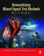
1.2.1 What’s an Analog Signal?
Analog signals concern electrical variables, their rate of change, and the associated energy levels. Any point on an analog signal may be at any level within a given range.
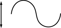
1.2.2 What’s a Digital Signal?
In this discussion, digital signals concern electrical variables that have been formatted to represent binary digits. Any point on a digital signal will be either at one of two levels, representing a binary 0 or binary 1; at some other level representing no data; or at a transition from one level to another.
1.2.3 However…
Digital is not always logic. For example, on a music CD (compact disc), analog information is encoded in digital form. And, as you might guess, logic is not always digital, Analog circuits can add, subtract, multiply, divide, and perform log calculations. Your car stereo includes a dual analog multiplier—it’s called an amplifier.
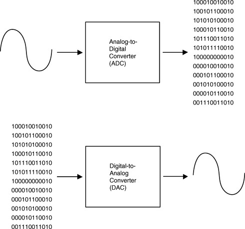
Sometimes, digital and analog are merged together, and that’s what mixed signal is all about. As just noted, the digital data on a music CD represents analog information in digital form. Or, consider an Analog-to-Digital converter (ADC), which generates digital values corresponding to analog input levels. The output of an Analog-to-Digital converter is digital, but it’s not logic. The output of an ADC is analog information that is represented in binary form.
There’s also the opposite case, where we encounter digital information in analog form. The transmit side of a modem converts digital data (like the ASCII text of an email) into modulated analog signals. Higher frequency data transmission gets an analog spin as well. An Ethernet transceiver shapes digital data into bipolar analog pulses with controlled slopes. Going back to the component level, let’s remember that the input to a Digital-to-Analog converter (DAC) is binary, but not logic. The input sequence to a DAC is simply analog information in digital form.
1.3 What Is a Mixed Signal Device?
Excellent question!1 Here’s an attempt at a definition:
A mixed signal device operates across digital and analog domains by representing or processing either analog or digital information in either analog or digital form.
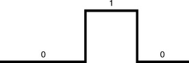
Consider a matrix that identifies a device according to function type and data type. Mixed signal devices cross diagonal boundaries of a process/data matrix.
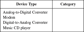
We would probably agree that an op amp is a “pure analog” type of device An op amp processes analog data, and performs an analog function. So it goes in quadrant “A” in Fig. 1.3. A NAND gate processes digital data, and performs a digital function, which puts it in quadrant “D.” A device that processes analog data with a digital function, or processes digital data with an analog function, is a mixed signal device. A mixed signal device crosses the boundaries between pure analog and pure digital.
Let’s try a few examples to get the hang of it. Which quadrant, or category, would you assign to the following device types?
1.4 What Isn’t Mixed Signal?
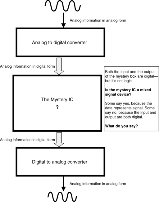
If you take these definitions to an extreme, you can make an argument that any integrated circuit is a mixed signal device. Deep inside a microprocessor are millions of transistors that are behaving in a very analog manner. Generally, we’ll see that mixed signal devices are loosely categorized according to the input/output pin function. If a device has analog and digital input and/or input pins, we’ll call it mixed signal. On the other hand, what if a device receives analog information in digital form, and then processes the signal information using digital techniques? If the output of this device is analog information in digital form, then the i/o pins are all digital. But the function is analog. A Digital Signal Processor (DSP) is such a device.
I’ve never heard of a company that comes out with their new slower and simpler part, have you? Developing additional features sometimes includes a higher level of integration. A cell phone, for example, might initially contain three integrated circuits for the voice-band processing—an input amplifier and A/D, a DSP device, and an output DAC and amplifier.
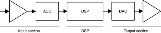
If all three sections are integrated into a single device, what do you have? Analog in, analog out—and digital signal processing in the middle.
1.5 Example of Mixed Signal Devices
There are many mixed signal device categories, including
1.5.1 Telecommunications Devices—Modems and Codecs
Telecommunications, or “telecom,” devices are used to transmit and receive audio, digital, or video information. The telephone system is one example of a telecommunications network, designed for voice communication and using a device called a codec. In another application, a mixed signal device called a modem interfaces between a computer and the phone line in order to transmit digital data on the analog-based phone system.
Codecs
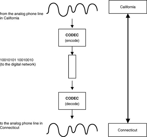
In order to efficiently process the analog signal information, the telephone system uses a device called a codec. Digital data is easier to transmit and store, and the purpose of the codec is to convert the audio voice analog signal into digital form. Codec is an abbreviation for “encoder and decoder.” Analog signal information is applied to the transmit, or encoder, section, which generates a digital bit stream. The receive, or decoder, section receives the digital bit stream, and reconstructs the analog signal information. From a simplified viewpoint, a codec can be described as a combination of an analog-to-digital converter and a digital-to-analog converter.
If you make a phone call from California to Connecticut, the voice information is actually transmitted in digital form. Codecs at either end of the connection are the interface between the analog phone signal and the digital phone system.
1.5.2 Micro-controllers with Embedded Analog
The ubiquitous micro-controller is found in applications ranging from industrial processes to consumer products such as microwave ovens and anti-lock brake systems. A powerful variation of the micro-controller chip includes on-chip analog-to-digital and digital-to-analog converters. This allows the controller to respond to analog input signals, and to produce a response in analog form. This combination of analog processing with digital logic illustrates a device category known as “digitally complex mixed signal.”
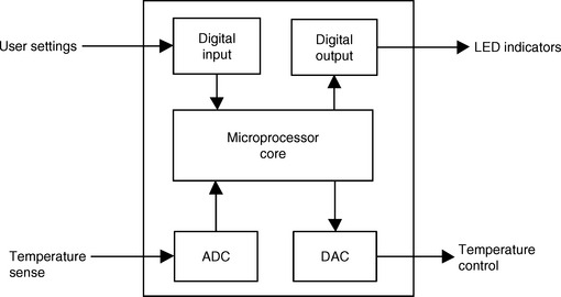
Suppose this is the micro-controller in an automatic bread-maker unit. The digital input port is used to read the various parameters that have been programmed by the user. The ADC input monitors the temperature of the bread dough. LED indicators are controlled by the digital output port, and the DAC output controls the bread-maker temperature.
During operation, the microprocessor core executes a program that reads the user parameters and the temperature data. In this example, the microprocessor program determines that, based on the user parameters, the temperature is too high. The program, in turn, sends a value to the digital output port that activates the “Over Temperature” LED and sends a digital value to the on-chip DAC to reduce the heat.
1.5.3 Discrete Converters
Converters are perhaps the most readily recognized type of mixed signal device. Analog-to-Digital converters accept an analog input, and generate a corresponding digital output code. Digital-to-Analog converters accept a digital input and generate an analog output level.
The design constraints for converters creates an inverse relationship between the analog precision and the conversion rate. Very high precision converters may feature an analog precision of one part per million, but have relatively slow conversion rates. High-speed converters may operate at several hundred megahertz, but tend to have relatively low analog precision. Depending on the end-use application, there are trade-offs concerning the required precision, speed, and cost. High-accuracy converters are found in audio and industrial control applications, whereas instrumentation and video applications utilize high-speed converters.
1.5.4 Mass Storage Interface
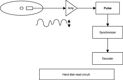
The hard disk drive unit of a personal computer requires extremely sophisticated mixed signal processing. The rotating media of the hard disk contains magnetically encoded digital data. The magnetic charges, arranged in concentric tracks of the disk, are sensed by positioning a coil mechanism, called the read head, over the track. As the disk rotates, the magnetic charge on the track creates an inductive pulse across the coil mechanism. The inductive pulse, in turn, generates current flow across the coil. The current pulse across a resistor produces a voltage signal.
The voltage pulse train from the disk read head is of low amplitude and high speed, and also contains a large amount of extraneous information, or noise. Variations in the location of the track cause corresponding variations in the amplitude and frequency of the digitally encoded analog signal. The analog signal frequency may be several hundred megahertz, with average peak amplitudes of less than 1 mV. Some of the mixed signal functions employed to extract the digital data from a hard disk include amplification, noise reduction, pulse detection, synchronization, and decoding.
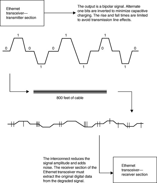
1.5.5 Ethernet Transceivers
Ethernet transceivers send and receive digital data in analog form. The constraints of the cable interconnect require that the transmitted digital bit stream be formatted to minimize the capacitance and transmission line effects. The receive side of the Ethernet transceiver must be able to properly extract the digital data from the degraded signal.
1.6 Automatic Test Equipment (ATE)
Now that we’ve got a general sense of what mixed signal devices are like, we can start to look at what mixed signal test is all about. To understand the architecture of a mixed signal test system, let’s look at automatic test equipment in general, and then examine logic test and analog test systems. Mixed signal test equipment includes characteristics of both digital and analog test systems.
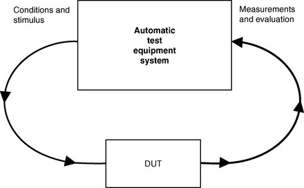
The conditions and stimulus provided by the ATE system include
The measurements performed by the ATE system include
The evaluation performed by the ATE system includes
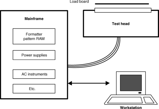
1.6.1 ATE System Components
The three primary components of an ATE system are the mainframe, the test head, and the workstation. The mainframe is the largest section, and contains the power supplies, DC system, logic system, and measurement instruments. The tester resources that are contained in the mainframe are connected to the test head via a cable set. The test head is designed to be small and light enough to easily interface with a handler or prober. Critical test hardware components that must be physically close to the Device Under Test (DUT), like the driver/receiver circuits, are located in the test head. The test head features a connector section that makes all of the test system resources available to the DUT. A custom circuit board, called the load board or device interface board, completes the connection path from the test head connection points to the DUT pins. The workstation is the computer system that runs the test program and serves as the interface between the test system and the user. Some test systems use a second computer, located in the mainframe, as the test system controller, while the workstation is dedicated to the user interface.
1.7 Comparing Logic Test and Mixed Signal Test
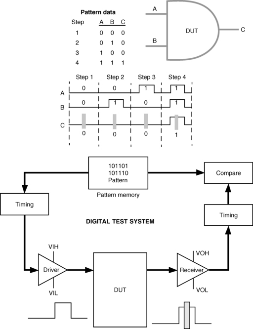
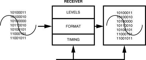
Let’s take a look at the different types of test systems, starting with logic testers. A logic tester will source digital data, capture digital data, and compare digital data against a model of the device function (pattern). When testing digital Integrated Circuits (ICs), the conditions and measurements are based on a pattern, which is a representation of the device functionality. The test system applies the pattern sequence of logic levels to the device under test and measures the response of the device by comparing the output against the expected pattern data.
1.7.1 Analog-only Test System
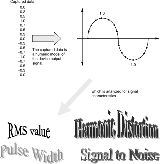
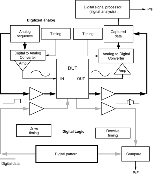
The test system applies the analog signal to the device under test via the signal source. The fixed signal source instruments used by early analog test systems have been almost entirely replaced by programmable signal instruments using digital synthesis techniques. An analog test system will source analog data, capture analog data, and analyze the captured analog data in relation to specified signal characteristics. Instead of driving a pattern as a digital logic tester does, an analog source converts a numeric model of the wave shape into an analog signal.
The test system captures the output signal with an ADC instrument, and stores a numeric replica, or digitized representation, of the signal. The digitized signal is then analyzed for signal characteristics by the test system DSP. The signal capture system performs a function similar to the pin receivers on a digital system, with two important differences. First, the test system’s analog capture instrument digitizes the DUT output with an ADC circuit, and stores a numeric replica of the signal information. Second, instead of comparing the device output with expected data, an analog test system performs an analysis of the output signal.
1.7.2 Mixed Signal Test Systems—Signal Source
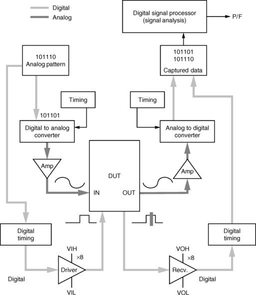
On a mixed signal test system the signal source is an arbitrary waveform generator with both analog and digital outputs. If the device under test is an ADC, then the tester must supply an analog input signal in analog form. If the device under test is a DAC, then the test system must supply an analog input signal in digital form. A numeric model of the waveform, called a sample set, is stored in the source RAM. This sample set is repeatedly cycled out to the DAC of the analog section, or to the timing and formatting circuit of the digital output section.
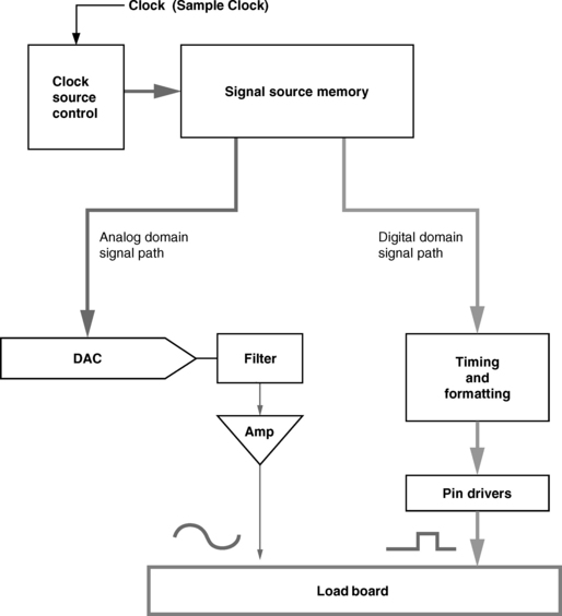
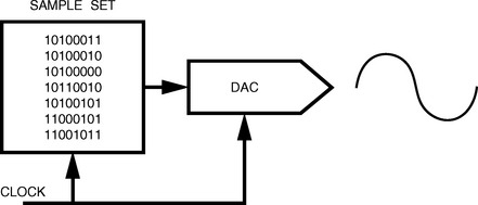
The analog side of the source works like a RAM behind a digital-to-analog converter. A numeric model of the waveform, called a sample set, is stored in the source RAM. This sample set is repeatedly cycled out to the DAC. The DAC, in turn, generates a sequence of voltage levels that produces the wave shape in analog form. The wave shape generated by the DAC is usually filtered and amplified before being presented to the DUT input.
The same signal source data set can be presented to the device in digital form through the digital output path. In that case, the signal data set is processed sequentially through the test system’s digital output timing, format, and drive circuits. The digital side of the source works just like drive data on a logic tester, except for where the data is stored, and what it represents. On a logic tester, the drive data is stored in pattern memory, and it represents the logic function input.
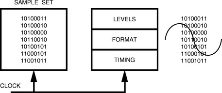
On a mixed signal tester, the source data may be stored in pattern memory or dedicated source memory, and it represents signal information. You still need to worry about timing, formatting, and levels, but the data no longer comes from the pattern, and it does not represent a logic function.
1.8 More about the Signal Source
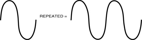
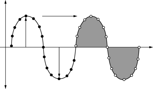
The hard part about getting the source to provide a proper input to the device is generating a periodic sample set. Remember that the source repeatedly loops on the sample set to generate a continuous wave form. The sample set, therefore, has to be set up so the loop-back generates a smooth transition.
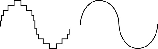
It’s usually helpful to be able to get the points in the sample set close together—it makes the wave shape smoother. The faster we can clock data through the DAC, the more sample points can be generated within a given period.

Amplitude resolution is also important. If we can only generate a few discrete levels, the output waveform will be crude. A 12-bit DAC, however, can generate 4,096 discrete levels, providing a higher level of accuracy.
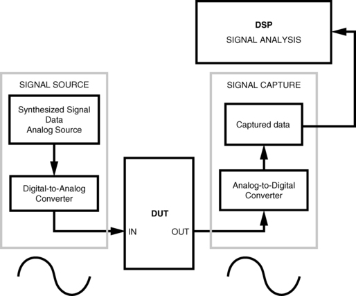
1.9 Mixed Signal Test System—Signal Capture
The capture section of a mixed signal tester is almost a mirror image of the signal source, acquiring analog information in either analog or digital form. Revisiting the previous example, let’s say the device under test is a digital-to-analog converter. The output of a DAC, of course, is an analog signal. Conversely, if the device under test is an analog-to-digital converter, then the device output is in digital form, but it’s not logic! The signal capture is a waveform digitizer with both analog and digital inputs.
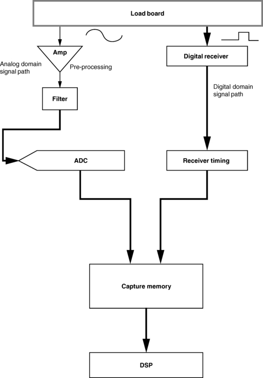
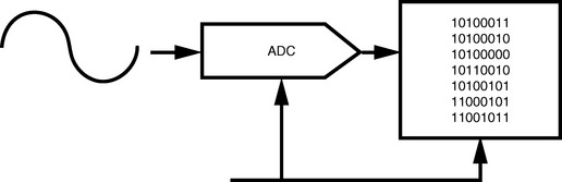
The analog side of the capture works like an ADC driving a RAM. The ADC samples and converts the analog signal from the device into a digital code corresponding to a numeric value. Each sampled point on the input waveform is successively digitized and stored in the capture RAM, resulting in a numeric replica of the analog signal from the device.
Like the source, the digital side of the capture is similar in function to the receive data on a logic tester. On a logic tester, the expected data is stored in pattern memory, and it is compared with the strobed logic states from the digital receiver. On a mixed signal tester, there is no expected data. Digital values from the DUT are stored in capture RAM and analyzed as a signal.
1.9.1 More about Signal Capture
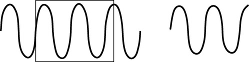
The capture section faces some of the same problems as the source. Setting up a periodic sample set on the capture side means the test system must capture an integer number of cycles for the signal under test. Acquiring an incomplete number of cycles of a signal will cause the capture “snap-shot” to misrepresent the actual data.
Like the source, it’s helpful to be able to get the points in the sample set close together—the faster we can clock data through the ADC, the less chance there is of “missing something” in the acquired data set.
Amplitude resolution controls the level of measurement precision. It’s a lot like using a voltmeter—the more digits we have, the less the uncertainty.

1.10 Mixed Signal Test System—Signal Analysis
The analysis section of a mixed signal tester evaluates the captured data as a signal. A digital signal processor (DSP) is used to extract signal characteristics in both the time domain and frequency domain.
A DSP processes the data from Capture RAM. Rather than comparing each bit in each vector against expected data, the DSP processes the entire sample set as a signal. The operational element of a DSP system is an array.
The DSP in a test system can be programmed to perform measurements as a virtual instrument. The DSP system does not control measurement hardware. It replaces it. The sample set representing the device output signal is processed with various DSP algorithms in order to analyze the data set for signal characteristics.
Using the DSP is like writing a separate sub-program within the test program using specialized commands. The DSP can use data from Capture RAM, from the main test program, from another array, or from disk. Results from the DSP sub-program are passed back to the main program as parametric values. These parametric values are then compared against pass/fail limits in the main program.
1.10.1 The Big Picture
A mixed signal test system will source analog data in either digital or analog form, capture analog data in either analog or digital form, and analyze the captured analog data in relation to specified signal characteristics.
Many mixed signal device types combine logic and mixed signal functions. The test system must combine logic test and mixed signal test on one platform.
1.10.2 More About Signal Analysis—Time Domain
Time domain signal analysis concerns the kind of signal information you might see on a oscilloscope.
1.10.3 Signal Analysis—Frequency Domain
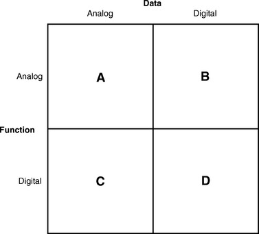
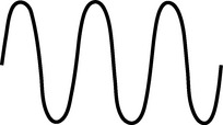
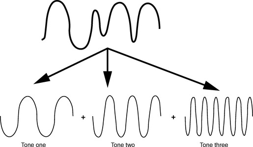
We’ve all been around oscilloscopes enough to feel pretty comfortable with time domain measurements, but what in the world is frequency domain? As it turns out, frequency domain is the kind of stuff you see on a spectrum analyzer. Let’s set the stage by looking at a special type of signal known as a multi-tone. In the example so far, we have been illustrating analog signals as a simple sine wave, as in Fig. 1.31.
Sometimes it is useful to have one signal that sums several signals into one waveform, as in Fig. 1.32.
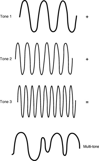
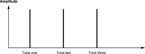
A multi-tone, therefore, is one signal that is made up of several different frequencies. Frequency domain analysis reverses this process. Transform functions deconstruct complex signals into their elemental components, and plot the relative amplitude of each component.
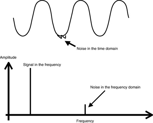
Once we’ve got frequency domain data, what can we do with it? Frequency domain testing often concerns evaluating characteristics of the signal shape or signal purity. Some features of the signal shape are more easily quantified in the frequency domain than in the time domain. For example, we might be able to use a scope to evaluate if a signal is noisy. But exactly how noisy is it? What is the amplitude and frequency of the noise? It’s hard to tell in the time domain, but looking at the signal in the frequency domain makes it crystal-clear.
Top Five Reasons to Know Mixed Signal Test
(with apologies to David Letterman!)
5. In the next industry recession, this knowledge will qualify us for jobs in TV
repair and alarm installation.
4. Our children and spouses seem to know a lot about mixed signals.
3. Everything is analog, anyway; and returning to our roots is a great cure for mid-life crisis.
2. The digital test acronyms are getting old. It’s time for some new acronyms And what does ISDN stand for, anyway? (ISDN stands for “I Still Don’t know!”)
1. Maybe we can use Digital Signal Processing to predict the stock market.
1. Mixed Signal Test is: (True or False)
| a. Arbitrary, Subjective, and Asinine. | T F |
| b. The same as Logic Test | T F |
| c. Based on analyzing device data as a signal. | T F |
2. The three sections of a Mixed Signal Test System are
3. In Logic Test, the device performance is evaluated by comparing the device output with expected binary logic states. In mixed signal test, the device output is tested by (choose one)
1There are two types of questions that I get from folks who attend my seminars—good questions, and excellent questions. Excellent questions are those to which I happen to know the answer.