
CHAPTER 2
Failsafe Software Design:
Embedded Programming in a Fail-Certain World
1. Software Matters
Ask yourself why you trust your microwave oven. Think about that as your daughter stares in the window and watches her milk warm. There in your kitchen is a ubiquitous lifestyle tool with components that could, in seconds, do severe harm to you or your family. Yet careful design of the physical cavity, the door, and various electronic and software interlocks render it as benign as a cereal spoon in most circumstances and far safer than the ordinary kitchen range next to it.
Meanwhile, tired and grumpy in the morning, you push a few buttons trusting utterly that your tea water or frozen sausage will heat up to your liking. A few beeps, the numbers glow, the magnetron energizes, and breakfast is served. The buttons always respond, the timer always counts down to zero, the door interlock always knows when you are in a hurry and safely disengages the innards. Somebody cares.
In my kitchen, on the wall across the room, hangs another piece of modern machinery: A two-line telephone by one of those late 1990 companies formerly known as AT&T. It’s lovely to look at, includes autodialing, conferencing, speaker phone, and two-line caller ID. The large LCD display is bordered by four “soft” buttons for menu control and—herein lies the rub—a red “new call” LED for each of the two lines.
As calls come in, the caller ID system dutifully decodes the name and number of the caller, recording this information together with the time, date, and incoming line, and the embedded software lights the “new call” LED for the appropriate line. Each call is marked “new” on the text screen until I review it once by sequencing through the list.
Curiously, sometimes as I sequence back through the list until I have seen the last new call, the LED steadfastly remains illuminated. If I sequence back through again, I see the software has clearly removed the “new” designation from each listed call; yet even if I delete the calls one by one, erasing the entire caller-ID list, the LED cheerfully continues to announce “new call.” If I pull the power to the phone, its clever brain keeps track of the situation and my Hal 9000 wall phone instantly boots back up glowing as if to announce, “I’m sorry Dave, but I can’t allow you to turn off that LED.” In designing this phone, somebody didn’t care quite so much.
It is possible to turn off the LED by a special sequence of strokes that clears memory, losing all record of all calls. In other words, the “soft reset” works. It didn’t take me long to think of that. In fact, the first time I witnessed my persistent “new call” light, I recognized the failure mode as an old friend and began tinkering to see which software pathways had been addressed and which had not. I have not only seen such an error before, I’ve created one. The circumstances were far less benign.
This chapter is about good software design for mission- and safety-critical systems. We will review simple principles and practices that help ensure systems work well and keep working. Our guiding mantra is Assume Fallibility.
We are generous in this assumption; don’t just blame your sales team or the sketchy documentation from your system architect. Assume fallibility in the hardware you are controlling, in the sensors you rely upon, in the next programmer that picks up your code, in your communications channels, in the idiot-proof end users, and, ego to the wind, in yourself. We will draw frequently from real-world examples to reinforce these points.
This chapter is not about the myriad guidance and regulating documents available for safety-sensitive and mission-critical software design. Certainly to those working in specific fields, documents such as DO-178b (avionics), MIL-STD-498 and -882 (military), and 21 CFR 820 (medical devices), will eventually be of keen interest. We shall instead consider some key unifying principles behind such guidance documents and attempt to motivate further interest in what sometimes appears to be tedious recitations of burdensome process.
Modern software engineers are often heavily schooled in how to employ good process and design strategies to find and avoid bugs. But in contrast to more physical engineering fields—electrical, mechanical, or civil—there is little emphasis placed on designing and compensating for failure modes. Where other fields employ redundancy and experience-driven safety factors as a matter of course, software developers are often tying their own hands in a tradition of minimalism and false assumptions.
This chapter is laid out in sections, each building on the previous. Section 2 is about process, and how and why it can work to your favor in engineering reliable critical systems. Section 3 delves into important core principles and patterns that arise repeatedly at all levels of failsafe design and implementation. Section 4 discusses the user interface and the key role it may play in the success of a mission—or safety—critical system. Section 5 addresses some of the design patterns in the context of the common practice of creating one’s own real-time operating software. Finally, section 6 considers an extended “what-if” scenario in which we examine a failsafe hardware design and consider how it might be usefully mimicked in software.
The recommendations and principles presented here were developed over many long years of both book learning and hands-on, hard-knocks experience. The topics will be of interest to applications software engineers moving into mission-critical/safety-sensitive systems work, as well as to hardware engineers transitioning to software work. They may also be of interest to those already in the field, either looking for new ways to think about their work or looking for material to help their manager understand why solid safety- and mission-critical software doesn’t often come cheap.
2. The Essence of Process
The development of engineered systems, and of software in particular, has been characterized from the start by evolving descriptions of process. The classic waterfall process, first defined in the 1950s, lays out a feed-forward effort in which requirements feed into design, design to implementation, implementation into test and verification, and so on down to delivery. The heart of the idea, sometimes referred to as the unmodified waterfall model, is illustrated in Fig. 2.1(A). Why “unmodified”? Because in practice, the waterfall model is nearly always modified.
The waterfall model is just an attempt to sketch on paper how engineers interact in sequential stages to produce a product. Many practitioners would add pre-process steps, such as a concept phase, and post-process steps, such as maintenance, as shown in Fig. 2.1(B). Many would further break down the stages into sub-blocks: design might become analysis, design, and test design, while implementation might become module implementation, module test, and integration. One example of a more refined form of the waterfall is shown in Fig. 2.1(C).
The added degrees of detail are attempts to capture a very complicated reality. Any engineer with real project experience could sit all day adding new boxes to the diagram—and probably remain unsatisfied. In fact, a true waterfall process is almost never used.
The exceptions are those rare cases where there is no time for, no money for, or simply no possibility of changing one’s mind. A one-off product, for example, might be sent out the door, ready or not, on an absolute limited budget; likewise, a satellite in orbit is not easy to reengineer once the final test data (launch!) are recorded.
Yet, even in those less common cases, there will almost certainly be some feedback between development stages—a prototype implemented gives information that changes the design, a test failed that changes the implementation—these small elements of feedback occur all the time. Even the termination of the process in “maintenance” is artificial since, nearly always, the results of any given project will feed into the next-generation product.
The closed-loop nature of most actual development leads to the spiral model of the development process, which simply recognizes the natural cycling between requirements definition, analysis, development, and testing. Various authors when describing the spiral call out different elements of the process, but the important concept is that good engineering is very seldom linear. Rather, good engineering is usually an iterative process of refining concepts and designs to converge on a solid result.


Figure 2.1: (A, B, C) The waterfall process diagram is a good metaphor for thinking about development, but does not capture the complicated reality of most engineering projects.
Attempts to better codify the development process have led to a host of ideas, and libraries of books on the topic. In addition to learning more about the waterfall and spiral methods, the avid reader may enjoy perusing the Internet for keywords like “agile,” “extreme,” “iterative,” “RUP,” and “RAD,” and seeing where those links take them. Attempts to firmly and definitively separate one process model from another or to quantify their respective failings fill nearly as many volumes as descriptions of the methods themselves.
At heart, the process chosen is often much less critical to success than the simple existence of a process. In fact, most guidance documents come to a similar conclusion. Well-known quality certifications, such as ISO 9001, do not specify a particular process; rather, they specify the existence of a process and consistent supporting documentation. The development process itself remains up to the organization. ISO 9000 is a body of quality standards, not an engineering guideline, but for purposes of applying process to mission- and safety-critical systems, thinking in terms of quality management is not far off the mark.
The purpose of defining a development process from a critical system perspective is to provide a clear framework for provability of the system. In the next section, provability is discussed as one of the fundamental principles of failsafe software design. In essence, the goal is to demonstrate that the system will perform as intended.
We typically speak about meeting requirements and specifications in terms of verification and validation. In general usage, verification refers to the process of ensuring that the project elements meet specifications, while validation considers whether the project satisfies its intended purpose. The common use of the two together, typically shortened to V & V, considers that the line between one and the other is sometimes fuzzy.
With this in mind, let us consider one more process model that captures concepts in a different way: the V-model, illustrated in Fig. 2.2(A). As drawn, the process clearly tends to flow from left to right, beginning in project definition, traversing implementation, integration, and test, and ending in operations and maintenance. However, the time arrow is only intended to indicate general flow, since information gained during test may easily feed back to a new iteration of coding or design. The V-model is not so concerned with a firm sequence of steps; one may use spiral, iterative, waterfall, or any other sequencing ideas to move the development team from requirements to delivery.
Rather than sequencing, the V-model is largely focusing on testability. The most important links of the diagram, from our perspective, are the verification-and-validation (V&V) flow arrows bridging the gap of the V. Definitions including requirements and specifications, analysis and architecture, and detailed design are set at stages on the descending leg on the left and are matched to corresponding tests, including system tests, integration testing, and module test at each ascending stage on the right.
System tests will naturally include testing of failure modes. We will see in the course of this chapter that encapsulating mission- and safety-critical elements of the design in ways that they can be isolated, implemented, and tested independently, goes a long way toward provability of those elements. Encapsulation lies at the heart of the design-for-test concept as it applies to software.
Iterative, stepwise, documented testing allows the engineer to build the critical elements of the system on a rock solid foundation. In particular, risk assessment and hazard analysis (RA/HA) become integral elements in the requirements and, subsequently, in the testing. Figure 2.2(B) illustrates how mission- and safety-critical elements can, and should, be called out, independently implemented, and independently verified. This critical-element subset of the V-model neatly captures how process relates to failsafe software design.

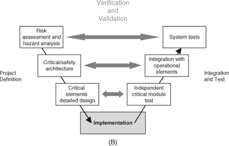
Figure 2.2: (A, B) The V-model of process reflects the ties between design and test aspects of a project. It can be adapted as a very good metaphor for understanding the process of developing, testing, and integrating safety- and mission-critical project pieces.
Any process model of software development is, at best, an approximation of reality, and the V-model is no better in that respect. The extreme emphasis on testing certainly will not appeal to applications programmers driven by tight deadlines rather than by hard mission- or safety-critical requirements. Rigid adherence will often be overkill for less demanding aspects of a project, such as general operations software. However, the V-model is an excellent graphic guide to best practices of traceability and provability for critical systems.
3. Three Principles for Design and Coding
3.1. What Does It Mean to Be Failsafe?
Having emphasized the importance of V&V in critical-system development, let’s take a step back and remember that testing isn’t everything. One problem with overemphasizing the design and test philosophy and relying on a third-party verification process is that if we design our tests to only test what we designed, then we are potentially blinding ourselves to unforeseen interaction of system elements.
Understanding what it means to be failsafe means understanding what can fail. We need to allow for unexpected failures both inside and outside the box. In a tip of the hat to Gödel’s classic logic proof, we need to recognize that we are nearly certain to experience failure modes in the field that were not realistically possible to anticipate in our design reviews.
Defining your embedded system as “the box,” consider first the outside-the-box elements. As the saying goes, nothing is idiot proof, given a sufficiently talented idiot. Your users are probably not idiots, in most cases, but they don’t necessarily think like you do. It is almost a certainty that your use cases and failure charts will not capture all the possible variations of input the system will ever see. Nor can you completely control the environments in which your system will be used—this is particularly true when the system has a long life cycle, such as medical or military projects that are likely to persist as legacy systems long after your primary design life.
Example 2.1. Outside-the-Box Testing
Sometimes what is obvious to the designer is not so obvious to the user. A medical test system required us to design a graphical interface that allowed patients to indicate their pain or other sensations by drawing on diagrams of their body. We very carefully thought out the interaction: The user circled regions of interest with a virtual pen. Each time the pen was lifted, a clever algorithm closed the curve and reduced the drawing to a shaded area of the body. This provided instant feedback to the patient and was very straightforward to anyone familiar with pen and paper. With a quick introduction by the medical practitioner, the patient was generally off and running.
Intriguingly, about 10% of the users found a second mode of interaction. Rather than circle the body region they wished to indicate, these users instead shaded it in, crayon style. The algorithm behaved predictably in response to this unplanned entry mode, providing positive feedback to the users just like a pen on paper so they continued to use it. This was a triumph of lucky design in some ways, but a big problem in others.
Data entered by shading produced vastly more closed-curve objects in a given drawing than data entered by simple circling. Our data analysis routines stepped through these closed-curve objects in a way that rendered the shaded data extremely slow to evaluate. So these 10% of our users required vastly disproportionate analysis time. We eventually wrote subroutines to combine overlapping closed curves into minimal convex hulls for purposes of both data compression and analysis speed—compensating for our own unplanned features.
The users had stepped beyond the designer’s intent and found another way of successfully using the system, with unforeseen consequences. They were unforeseen because the use case variation was completely outside the design scope. It just happened to work. No amount of planned testing was likely to reveal the issue.
In this very same system a bored alpha tester also took us quite literally outside the box. The young gentleman, a university student and research intern, was asked to test our system between his other tasks. He wasn’t given specific test instructions, just asked to try out different functions and let us know if anything broke. It wasn’t long until he succeeded.
Asked to demonstrate for us, he proceeded to circle the entire screen several times, lift his pen, and then make one more dot somewhere else on the screen. The system crashed instantly. In fact, he had triggered a rather unlikely buffer overrun condition that we promptly addressed. This was completely outside any rational use case since there was no reason any user would ever need to circle the entire screen, let alone more than once. It took a bored lad scribbling at random to find our failure mode.
What could a bored lad achieve by punching buttons at random on your embedded control device? What unintended user interactions might be supported, even reinforced by your user interface? You will not predict them all. Keep that in mind when contemplating the value of cross checks and critical element redundancies.
Consider next the inside-the-box elements. Today’s embedded processors sport an abundance of power and memory resources and encourage increasingly complex embedded code: complex code that is less and less provable. We now need to triage our complex systems and isolate critical elements from ordinary operations code. Even so, code for critical-system elements often interact with less reliable subsystems. Consider, for example, the now common situation of running your front-end operations and user interface on consumer-grade Windows. Even in the best of circumstances, bugs in large software systems can be insidious, with sleeper failure modes lying in wait for just the right combination of inputs or just the right intermittent hardware glitch. What about the future? If your code is subject to future modification, how resilient is it to bugs introduced later? How much testing will need to be repeated?
We simply cannot rely on high-level system testing of complex mission- and safety-critical designs. We need to fight the battle on the ground, at the foundation level of our design and coding. We begin with three strategic principles:
• Readability
• Redundancy
• Provability
The first of these principles, readability, will be familiar in some form or other to every software engineer who has cracked a textbook in the last 30 years. The details of the idea have evolved substantially and coding styles have gone in and out of fashion, but the concept remains and certain fundamentals persist, including clear blocking of code, transparent naming of variables, functions, and properties, extensive commenting: All of these niceties make it easier for your colleagues to read and understand your code and for you to remember what you were doing when the boss asks you to modify the code a year from now.
Example 2.2. Human Readable Is Human Recoverable
All software engineers go through a phase where they enjoy maximizing efficiency. It’s amazing how much information you can pack into a binary file, coding bits and bytes in tight structures. It’s also amazing how useless that information can become if corresponding “reader” software isn’t available. If the binary data files become corrupted, then one can only hope the original engineer took the time to write recovery functions into the reader software. Otherwise, the hour is truly dark.
There are instances where tight data are key. Perhaps there are system storage limitations. Perhaps the data are naturally structured, such as in image or audio files. There are also instances where an embedded system is fundamentally designed to process information for compression or transmission—think mobile phones.
There are, however, many, many instances where data are being logged or recorded for testing purposes on typical modern systems with typical modern storage capacities. In such cases the additional overhead of writing an ASCII field name with the data or in writing ASCII coded text is often trivial compared to the benefits of having a human readable output quickly available to review in any handy text editor.
The Linux world has long recognized the usefulness of ASCII control files and logs. Ironically, after years of increasingly obscure file formatting, even Windows now incorporates ASCII-coded configuration and log files.
In my work in experimental test systems and embedded design, it becomes impossible to count the occasions where an ASCII log file, or an ASCII coded header to a binary data file, has saved the day. Cases include testing, debugging, crash recovery, and a few substantial projects in legacy data recovery where systems have fallen into disuse.
Not long ago I received a phone call from a researcher asking my help on understanding data that we collected with a custom test system almost 20 years ago. The system no longer exists, and even the hardware it ran on is impossible to reproduce—but this gentleman had file after file of archived data from our work. I walked him through the data file headers, written in long-form text, which fully documented the experimental setup and each data field written in the file below. Needless to say, he was rather pleased.
Documentation gets lost. Code gets lost. Processors and operating systems change. Even storage media evolves. If your data are not stored in a well-documented and broadly applied standard format and your requirements are not truly data intensive by modern standards, consider keeping it human readable wherever possible.
Readability maximizes transparency, facilitating verification and bug fixes. In the realm of applications programming, these are good practices. In the realm of mission- and safety-sensitive software, these are critical practices. When the failure of your code could result in the loss of a quarter-billion-dollar aircraft and human lives, clarity counts.
As with process, it is not my intent to espouse a particular style convention. Depending on your background, the tools you work in, and your organization’s standards, your preferred style may vary quite a bit. However, general experience suggests that using as long and as descriptive a name as your own convention and software tools permit often goes a long way toward success. When code reads like a sentence, it becomes much more readable and much easier to verify. A friend who programs for a major airline-industry software provider relates the story of getting slightly embarrassing attention over her innocent choice of the polymorphic method name “isTurnedOn()” for checking the status of system objects. However, one may rest assured that the code reviewers had no trouble in understanding and verifying the logic during the walk-through.
Keep in mind that meaningful naming conventions also require consistent spelling. In an age when modern programming languages are reintroducing untyped, undeclared, and runtime allocated variables, it pays to get a little old school when it comes to your critical system elements. When writing code, turn on compiler flags that require explicit declarations and use code evaluation tools that help you find orphan spellings.
Programming standards have evolved through the introduction of functions and subroutines in software pre-history, to the organizational rules of structured programming, to the current object-oriented vogue. Modern embedded programmers may code in languages from assembly to Java these days, so there is not a one-size-fits-all solution. However, adapting a consistent strategy and complying with your own standards is the first step in any good practice manual.
Side Bar: Is OO the Enemy of Transparency
To the experienced embedded software engineer, there are advantages and tradeoffs to every tool. Some occasions call for hand-optimized assembly code, while others afford the luxury of the latest UML graphic design tools. Having lived through both the structured programming and objectoriented (OO) heydays, it is interesting to note that not all the purported gains of OO are blessings to the mission-critical programmer. In particular, inheritance and polymorphism can be sticky concepts since, in practical situations, progressive development of software or reuse of older code often entails modifications of root classes, potentially triggering an extensive re-verification process. If someone’s safety is on the line, every test pass may need to be deep and exhaustive.
OO gurus will take exception. In fact, the same aspects of OO that allow one to define inheritance will aid in tracing dependencies and defining test plans. It is certainly possible to adhere to good OO design patterns and build systems where properties of OO work to the mission-critical programmer’s advantage. In the author’s experience, however, this is seldom achieved, since evolving hardware choices and other system considerations combine with delivery time pressures to spoil design perfection. Particularly in complicated event-driven object code where user input and time-cued events continually modify the system state, it becomes remarkably easy to lose track of which methods or call-backs handle which hardware checks, resets, and state updates under which circumstances. Independence of the critical safety code as espoused in the chapter can help mitigate those risks.
OO programming does have advantages. In particular, OO allows easy abstraction of real-world elements so that the code interaction model is more intuitively understandable. The “Hardware as Software” exercise in this chapter (see section 6) is intentionally sketched using an old-school, structured subroutine model. It would be much more transparent to sketch a UML diagram where an object like the “PrimaryInterlockSwitch” had a property “Closed.” However, while the OO model clarifies intent, it deliberately hides functionality. Inside the “PrimaryInterlockSwitch” object, someone would eventually have to write and verify a subroutine that acted on changes in the property “Closed,” and the hardware control aspects of that subroutine code would look rather similar to the subroutine presented. The UML object model must be linked to the hardware eventually.
OO may have a natural appeal to hardware engineers moving into software engineering. OO programming can be thought of analogously to component-based hardware design. In many ways, each object class is like a discrete device, with external interactions governed entirely by fixed public “properties” and “methods” in the manner of the documented electrical connections on a chip. The internal manner of function is not of concern to the user; only the published behavior is important.
Relying on the hidden embedded functionality, however, dictates thorough component module testing. It also dictates isolation and tracking of critical functions—a recurrent theme of this chapter.
This brings us to another point: a key positive feature that both structured and OO programming styles share is encapsulation. Use it! As discussed in the text, encapsulation helps enable both readability and provability. However, the existence of encapsulation is not sufficient—think very carefully at the design stage about how to employ encapsulation. If safety and critical elements of the system are scattered across the system classes, the design may be a recipe for disaster. Complex interactions between classes can conceal unanticipated failure modes. Extensive, repeated testing may become necessary at each software change to verify critical system behaviors. Because of lack of transparency, verification can become a matter of probabilities rather than certainty.
How does one overcome the transparency issues that can arise in OO programming? First and foremost, by applying the principles of redundancy and provability to the safety- and missioncritical aspects of the system. Burying critical safety checks in your operational classes is both unnecessary and poor practice. Instead, encapsulate critical software aspects in independent classes that can be verified independently of other operations code.
Yes, one may very well incorporate secondary safety and status checks in operational code that are redundant with the independent safety modules; however, by clearly calling out critical hazard mitigations in the object design, the system will become readily verifiable and inherently lower risk.
The second principle is redundancy. This concept may be natural to the mechanical engineer designing bridges, but it is seldom second nature to the applications software engineer who relies habitually on computer hardware and operating systems to perform as advertised. It has been said that the best engineers are lazy—that is to say, we innovate intensively to save work in the long run. For many, the elegance of software somehow lies in the art of creating minimal code to achieve maximal effect. It may seem counterintuitive to save work by allowing more than one piece of code to perform the same task. It’s not.
In fact we save work, in the long run, because by carefully employing redundancy we are enabling the last of the three principles: provability. In particular, we enhance provability by reducing the required testing load.
Consider what happens if you introduce a change in the operational code that mistakenly removes or inactivates a sequential safety check. Consider what happens if someone else comes along and mucks up your code with their own ideas—perhaps simply because they didn’t fully understand the dependencies. No one is perfect and any practicing engineer can probably recount a few such experiences.
At another level, consider that software is inherently reliant upon the hardware that supports it. Consider how completely you want to rely on your internal state variables accurately reflecting the real-world environment if an erroneous hardware setting could permanently injure an innocent user. Hardware engineers certainly don’t take their hardware’s continued normal operation on faith; likewise, critical system software engineers should not take either the hardware or their own software on faith.
We address these issues by clearly calling out and enabling mission-critical and safety elements in separate, verifiable code. If the disabled in-line safety check were backed up by a redundant, independent-watchdog safety check, a potentially life threatening bug can be reduced to merely an important future software patch. If the system is able to use independent sensors to verify reality, rather than relying on internal state variables, entire classes of failure modes can be detected and avoided.
Working field software should not even trust itself. In space, military, medical, and heavyindustry environments, well-designed embedded systems always start up with a thorough self-check. Is the code intact according to checksum tests? Did it load correctly? Are there any stuck bits, registers, or sensors? Space systems, due to ionizing radiation exposure, sometimes include means of continually verifying software, processor, and memory conformity during operation—at times replicating entire embedded subsystems in two or three copies.
Hardware engineers are unashamed of redundancy because they are trained to design to failure modes. Examine the schematic in section 6 (Figure 2.6) and you will find that multiple redundant interlocks consume most of the design. Software engineers are sometimes burdened with an education that suggests if only they follow certain steps they should be able to achieve provable, efficient, bug-free code. That thinking is not wrong, but it is dangerously self-deceiving. Software designers need to fundamentally understand that rushed releases, borrowed code, broken updates, flakey hardware, and honest mistakes are part and parcel to the field. A critically designed highway bridge may, with some luck, carry traffic for years at its design load, but a three-times safety factor over that expected load will truly protect the health and safety of the public in the face of the unpredictable.
Assume fallibility and create failsafe watchdog checks that address not only failure of the system and user error, but also failure of the code. (See Example 2.4.) Just as in building airplanes and bridges, critical-system software must include redundancy: design a complete operational system meeting requirements and, in addition, build in independent watchdog and backup elements to protect against critical failures.
Example 2.4. Brain Stimulation Backup
What happens when a little change in code mucks things up in a working system? A failsafe watchdog can really improve your day. In the late 1990s, I was involved in designing softwarecontrolled test systems that included electrical brain stimulation. We used the stimulation in conjunction with behavioral tasks to assist surgeons in mapping language and motor skills in the brain before surgery. These systems were noncommercial and we frequently updated our software to incorporate new specialized tests for individual patients under very tight time pressure. Several tightly choreographed computers performed numerous operations, including presenting visual and audio cues to a patient, and recording EEG, speech, and reaction time, all while stimulating across pairs of electrodes laid directly on the brain.
During operation, the general sequence of events was supposed to work like this:
Send trial information to recording computer
Begin recording
Turn on electrical stimulation
Present psychological test cue
Record patient response
End psychological test
Turn off electrical stimulation
End Recording
Store data
Repeat for each trial until done
Caveats abounded. Chief among them was that electrical stimulation could under no circumstances remain active for longer than 5 seconds for safety reasons. The length of the psychological test could vary and patient response time was up to the subject, meaning that the timing and even the sequence of events were never completely predictable. The system incorporated several levels of software cross-checks and, of course, emergency hardware disconnects.
The hospital monitored human subjects work with an excellent group of independent engineers known as the “clinical engineering” group. Our job was to build it; their job was to try to break it and to make sure, in the worst case, that it didn’t hurt anyone.
As our work progressed, the physicians asked us to speed up testing by allowing multiple psychological tests to occur during a single electrical stimulation period. This necessitated a delicate restringing of the control code, and time pressures always meant too little testing. In due course, we demonstrated the updated system to clinical engineering, verifying that we could interrupt stimulation at any point using keyboard inputs and that the multitest sequencing worked properly. After an hour or so, by chance, we discovered a bug: In certain rare cases, where the last scheduled psychological test overlapped the scheduled electrical stimulation endpoint, a flag was miss-set and the state variables lost track of the fact that the stimulator was on.
It was rather stomach-wrenching to have a deeply concerned third party ask, “Why is the stimulation still on?” during this sort of clearance demonstration. However, the clinical engineer immediately checked the electrical stimulator itself and corrected himself: the stimulation was off. In fact, while the computer screen was still indicating “stimulation on” in rather bold and alarming fashion, watchdog timer code that had never before been executed in need, had already detected the 5-second timeout limit and turned the juice off. The system corrected its erroneous display shortly thereafter, verifying reality by checking the stimulation relay status before moving on to the next trial sequence.
Perhaps this reminds you of the “new call” light mentioned in the introduction? It should. (See Example 2.8.) There was no way of directly monitoring stimulation status from the control computer in this case. Instead, a function named something like ElectricalStimOn() checked the control relay and reported whether it was open or closed via a hardware register bit. This function did not fail; instead the operations code simply failed to clear the blinking warning from the display because the check-and-update sequence was skipped. The error is akin to the problems with setting internal-state variables to mimic reality; in this case, the presence or absence or a line of text on the display was the “flag” that a human operator saw and it was simply out of synch.
Our clinical system came out ahead of my telephone, with its perpetual “new call” situation, because of strategic redundancy: my software contained independent watchdog safety code and verified reality by forcing things to known conditions at the end of each trial.
The bug was easy to fix once detected. The failsafe watchdog timer not only saved face, it also would have fully protected the patient had one been attached. Ultimately, our third-party reviewer was very favorably impressed with the safe, demonstrable redundancy of the system, especially given the non-commercial nature of the project and the likelihood of frequent future changes.
Independently designed and tested failsafe routines that are not part of the primary control code are key to reliable, demonstrable safety. Put more simply: CYA.
This brings us to the third principle: provability. Certain small embedded systems are in fact simple enough to examine and prove exhaustively. These are increasingly rare, and even where they are possible, maintenance and update processes become significant costs when one must re-verify everything.
In general, operational code in modern systems is simply too complex (or too expensive) to test exhaustively. Triage in the form of RA/HA is the key to getting our hands around the problem. We can use the above principles to verify the mission- and safety-critical system aspects to achieve a failsafe product.
Some aspects of provability come about in code validation, others in functional system design. Encapsulation of mission- and safety-critical code not only aids readability, it also enables provability. For example, by designing a watchdog monitoring thread that is independent of my system operations code, I encapsulate a critical aspect of my system. That safety check can be verified in early code reviews and in independent systems testing and thereafter frozen out of most future updates. I then know with some certainty that even if the more intricate operations code is broken in future updates, I have a friendly big brother watching things. Not only is encapsulated code thread independent of the other components, making for a reliable functional design, it is also compact and easy to read and verify without tracking through the full complexities of operations.
Even where code is not multithreaded, a natural extension of this idea applies. Encapsulate the mission- or safety-critical aspect in a standalone function call that can be verified, frozen, and relied upon. For example, MakeLaserSafe might be a nice function name for a sequence of events that included testing for lack of energy in the exciter, powering down the laser if necessary, engaging interlocks, and warning the user if anything fails. TestLaserSafe might be a nice function name for a routine that checked the exciter, checked the interlocks, and set display warnings accordingly. Once these safety routines were coded, verified, and frozen, the presence of these function calls in any updated operation code would become part of the standard verification procedure.
In single-threaded code designs, even where outside physical events cannot affect hardware status, it is good practice to use these sorts of calls redundantly. In this case, redundancy enables provability. For example, one might call MakeLaserSafe followed by TestLaserSafe in the operations code as part of ending an ordinary cutting operation. The function UnlockDoor might make the very same calls, redundantly, before operating the door solenoid. This would protect against later bugs in which a programmer fails to sequence the commands properly. It would also allow the UnlockDoor command to be verified against the RA/HA chart independently of the operations code. Conversely, it would allow operations code updates to be verified without relying on the institutional memory of whether or not UnlockDoor makes the system safe.
With modern fast hardware and cheap memory, the only real excuse to avoid such redundancy is ultra tight real-time operating constraints. But generally in such circumstances the entire response-time-critical operating branch becomes a critical component subject to verification and review with each modification.
Another aspect of provability occurs during operation, but must be planned for during design. The idea can be reduced to verify reality.
Again, the provability and redundancy ideas complement each other. In the example above, we not only turned off the laser, we made sure it was off, hopefully by means of an independent hardware sensor. Were we to use only software state variables and believe that the laser was off simply because we turned it off, then our user might one day experience a very unpleasant failure mode. Hardware busses fail, registers fail, relays stick. . . . Safety cannot be left to an internal model of the physical system that is not continuously updated and verified.
When software can issue a hardware command but not confirm the result, the situation is often referred to as open-loop control. Open-loop control leads to assumptions by its nature; and unverified assumptions are very, very frequently the root cause of high-risk failure modes in safety- and mission-critical systems.
In a safety-critical system, your software control is extremely likely to be backed up by hardware interlocks. In fact, unless it is physically impossible to achieve, it had better be. On the one hand, don’t leave home without making the hardware as safe as possible in its own right. On the other hand, do not rely on hardware safeties to compensate for your code failures. Hardware switches and interlocks alone, in some sense, work in big broad strokes, while software can generally act much more nimbly to detect, compensate for, and even predict hardware failures.
3.2. Safety (and Mission) First
For anyone who has wandered the grounds of an industrial lab or manufacturing plant, “safety first” seems like an overworked catch phrase. In fact, in mission- and safety-critical system design, it is an actionable design approach. This approach begins with risk assessment and hazard analysis.
Hazard analysis is a process used to assess risk. The hazard analysis identifies and quantifies risks and then defines means of controlling or eliminating them. This process occurs in the very early stages of the software development cycle, often before operational features are fully specified.
A common format for such documents is a multicolumn matrix, such as the following.
![]()
Failure modes may be caused by equipment problems, software problems, user actions, environmental situations, hardware or power glitches, or even acts of God. The hazard level typically reflects at least three levels of risk assessment characterizing the significance of the threat. This is sometimes a combination of the possible cost of the failure mode (in safety or mission risk) combined with its likelihood of occurrence. In general, however, one attempts to write down everything bad that could happen since it is often meaningless to sort out likelihood early in the design. The design action is a brief statement of how we intend to control the hazard in our design—always stated in an actionable and traceable way.
The three columns show the essence of the idea. Many practitioners develop their analysis with several more columns, breaking out information and adding additional details specific to the project or to company process. For example, hazard level might be explicitly separated into estimated probability of occurrence and risk level upon occurrence. Design action might be complemented with a column assigning the task to a project group, and each row may include a traceable number or code to be used in tracking.
From the perspective of software, we need to know which of the system-level RA/HA items are actionable. These items should form the basis of a software RA/HA matrix. To that matrix we should add our own additions. These include software-specific risks such as hidden hardware dependencies, potential for state verification, and software bugs that might slip through in initial coding or updates. These are exactly the topics we’ve discussed above.
Such hidden software risks may not always be on the system engineer’s mind, and where they pose significant potential for safety or mission compromise, they should be brought to the overall design group’s attention. They should also be documented and tracked within the software group.
We need to recognize that common software failures can be harder to explicitly predict and harder to identify and trace when they occur than common hardware failures (Fig. 2.3). It is incumbent upon the software engineer to recognize the limitations in our craft, to convey the risks to those who need to know, and to design and code in a way that compensates for these recognized, but often nebulous, risks.
In many systems both safety- and mission-critical aspects arise. Sometimes they are related; sometimes they are not. In medical products development, it is common to focus heavily on safety since this is what the Food and Drug Administration and other regulatory agencies will audit and control. But in any embedded software design, there will also be missioncritical aspects that are important to the success and usability of the product. A product may be perfectly safe but ineffective, rendering it a failure in its mission. Why build expensive doorstops? Safe and effective products are our goal, and we achieve this by tracking the balance of mission- and safety-critical aspects of a project.

Figure 2.3: Burnt offering: Common software failures can be harder to predict and, when they occur, much harder to identify and trace than common hardware failures. (Photo courtesy of Jeffrey M. Sieracki)
By tracking both aspects in parallel, a critical system designer—or any embedded system engineer—can make clear, traceable choices that increase probability of producing a working, verifiable system that meets design goals.
Consider again the V&V process in Fig. 2.2(B). After we quantify our safety- and mission-critical aspects in an RA/HA chart, we move on to designing the critical architecture components to address this list. We then design code modules to enable this critical backbone architecture. Insofar as is possible, this design will be independent of the operational architecture that we design later to meet the basic functional goals.
After implementation, we assemble our components working bottom up to test and verify. Each descending leg of the V corresponds to an ascending verification step. The critical elements detail design maps to independent testing of those modules, and the critical architecture informs the integration of those modules as well as integration with the operational elements of the system. Finally, the list of critical aspects the original RA/HA chart directly drives set of system-level validations, including both functional tests and RA/HA-specific end-to-end design reviews and code walk-through.
By starting the project with the critical elements rather than general operational aspects of the project, we design to the failure modes. We can then move forward on the feature-driven aspects of the project with some confidence that we have covered ourselves on the critical side. In the author’s experience, this safety-first approach often leads to clearer and simpler operational code for two reasons: (1) the operational code can be written directly to the feature list without thinking and rethinking what might go wrong at every step; and (2) the critical design architecture often becomes the backbone of the basic operations architecture with very little additional overhead.
Use cases can also be extended to failure modes. Modern software designers often build up a collection of storylines that helps all stakeholders visualize how the system will interact with users and the environment. These are called use cases. They are generally used to help define user interfaces and operations sequences to enable the system to better serve its application. In practice, their use is typically emphasized in early design stages to help flesh out the look and feel with respect to the basic mission; their importance generally diminishes as development progresses and the actual system elements are available for examination and testing. Application of use causes is often limited to understanding and defining core operations elements. However, they can also serve as a powerful tool for evaluating failure modes and in planning for risk mitigation in safety- and mission-critical systems.
What happens if an alarm sounds in my plant control center or on my aircraft cockpit panel? Is there a defined user checklist? Are there mechanisms by which a user can acknowledge the situation and eliminate the distraction? What if the user simply silences the alarm and moves on—is there contingency code for ensuring that critical alarms cannot be ignored?
Suppose that a primary control fails. Consider the steps by which the user (or the embedded software) will enable a backup system. Is it natural and achievable under expected operating conditions? Are additional steps required to ensure safety during transition?
Consider the myriad insidious software errors discussed earlier. Can the code help a user recognize possible internal failure? At a minimum, we should log inconsistencies in internal states variables and sensors so that they can be reviewed later. Failure of a hardware system to respond as expected could be a hardware error or a software bug. Where detection is possible, it should be addressed automatically to the fullest extent possible.
The failure-mode use-case analysis should assess the risks associated with the problem, whether and how the user will be notified, and how to log the error and notify technicians that something must be investigated. The “check engine” light in your car is a classic example of dealing with low-risk failure modes—by simple means it notifies the user that a non-critical problem exists that cannot quickly be acted upon. The actual problem is logged and a technician can later short a few jumpers to request that the embedded software report the problem in detail.
In some cases, the failure will present a clear and present hazard to safety or to the critical mission of the system. The failure-mode use case should carefully address how the user is notified, and whether and how the system is shut down, the mission aborted, or the situation is otherwise made safe as appropriate.
Example 2.5. Expecting the Unexpected
We give a great deal of emphasis to risk assessment and hazard analysis, as, indeed, we should. These critical paths become part of our design and traceable elements in our test plan. Similarly, requirements documents and specifications lead to our core operational design and operational test plan.
In both commercial and research systems requirements, there are always requirements that will not be documented in advance. These include tacit assumptions or environmental factors that do not become apparent until we get to field releases and beta testing.
In developing a computer-based medical research system designed to be left alone with a patient, we did not fully consider the habits and expectations of the clinical staff. Commercial medical devices are nearly always either permanently installed, equipped with battery backup, or both. Nurses thought nothing of walking in, unplugging the computer, and wheeling it out of the way. In the days before uninterruptible power supplies became cheap and ubiquitous, this was a serious problem. Hours of patient testing could be lost if the system was not shut down properly. Thus “plug-pull tolerance” made its way to the top of the evolving requirements list after a few weeks in the field. By ensuring that the software flushed file buffers early and often and that we tracked recovery information in case of sudden interruption, we prevented loss of data. This meant less wasted patient time and fewer surly exchanges between the research and medical staffs.
To the surprise of the surgeon who directed the lab, the change was fairly quick and easy. The change was accomplished with minor, traceable edits to the working code and one small additional module. There were three changes: (1) The file system was flushed after each minimal unit of meaningful data was collected. This required a single line of code and did not impose any unacceptable delays in operation since it was coordinated with a natural momentary break in the test sequence. (2) An indicator flag file was written before patient testing began and cleared after testing ended. (3) On start-up, the software checked for the flag file and, if present, executed a separate subroutine that checked the last data file for any partially written information and cleaned it up. The software then passed parameters to the existing code to restore the patient interface to the point at which the plug was pulled.
The code was already well encapsulated. The only modification to the critical core control code was the file flush—a single line of code, easily verified. The other modifications were outside the core control code and added to the start-up and wrap-up sequences—again with one or two lines of code, in clear sequence, easily verified. Existing well-tested software modules already worked reliably and major modification and retesting was unnecessary. The new clean-up subroutine was created and verified separately.
Inevitably, your requirements and your code will progress, so encapsulate and generalize safety- and mission-critical aspects. Thinking and designing modularly is efficient at every step, from documentation to code delivery to testing.
In addition to failure-mode use cases, also consider the postmortem in the event of failure. Consider how the technicians can learn what went wrong so that they can repair the system, or convey issues to the designer to fix in the next update.
With respect to good design practices, we can learn a lot from the black boxes used in aircraft and other public transportation. At the hardware level, they follow all of the mission-critical design guidance steps that we are advocating for software. The boxes comprise an independent, encapsulated, and separately tested subsystem. The encapsulated design is limited to a specific, narrow critical mission, and is not subject to revision in conjunction with the rest of the operational system.
Black boxes have become ubiquitous in transportation and are, to some extent, becoming ubiquitous in applications software—in the latter case, they take the form of system event logs. In embedded systems, they have often been limited to simple error-state flags, such as the “check engine” model. With increasingly cheap computing and memory capacity, the safety- and mission-critical designer has little excuse not to include a means to keep detailed track of field problems.
3.3. Verification and Redundancy in the Implementation Process
Relying on encapsulated functionality, as discussed previously, dictates thorough component module testing. These critical paths become part of the design and should be traceable elements in the test plan, just as requirements and specifications documents lead to the core operational design and operational test plan.
To the extent possible, meet specific needs with specific traceable code. In some cases, this may be a watchdog timer running on a separate thread; in others, it may mean encapsulating hardware and sensor interactions; and in still others, it may be as simple as laying out code so that a master loop clearly and unavoidably checks and confirms hardware status on each pass-through.
Ideally, each software mitigation step listed in the RA/HA should be traceable to a specific, encapsulated code segment. This will reduce risk of unforeseen interactions, simplify verification, and increase the likelihood of delivering a robust, operational system.
In practice, not every aspect of every mitigation step can be encapsulated. For example, start-up code needs to make calls to initiate certain modules. Operational sequence code may also need to make specific tests to take advantage of the encapsulated aspects—such as making the laser safe before opening the door. As discussed earlier, however, a certain degree of redundancy can help simplify verification and ensure compliance with required procedure.
Non-encapsulated steps need to be conveyed clearly to code designers and verified as a matter of course in code reviews. Permitting and encouraging strategic code redundancy where safety- and mission-hardware interaction occurs not only aids the reviewer’s work, but also provides a safety net. It is certainly possible to achieve Six-Sigma level verification without doing so, but the potential for hidden bugs in complex modern software is so high that the belt-and-suspenders approach of targeted redundancy will almost certainly be a safer and more cost-effective plan.
Targeted redundancy is not synonymous with bloated code. Repeated elements are limited to calls that verify critical hardware status, and the redundancy occurs in that these calls may occur in more than one subroutine that may be part of a sequential code sequence. The hardware functions should be encapsulated and the operational code clean and readable. Old-school software efficiency hounds (the author among them) can take solace in the reality that modern chip designers often must include a high percentage of entirely redundant circuit regions on their silicon dies to compensate for frequent failures in the manufacturing process. A high mission success rate takes precedence, and carefully applied redundancy is ultimately efficient and cost effective.
Version control, test and control plans, and linked verification of the elements in the RA/HA matrix are the means by which safety- and mission-critical elements are traced and ensured in the final product. The process documentation often feels like a burdensome evil when an engineer would rather get down to coding, but it is ultimately a powerful tool for quality assurance. Taken with a positive view, the process can be leveraged by the critical-system engineer to make implementation a very targeted and efficient process.
Other elements of redundancy are becoming standard fare in modern development. A generation ago, programmers tended to be quite curmudgeonly about their peers looking over their shoulders. Today code reviews are ingrained in the development process. By subjecting each function call and line of code to multiple pairs of eyes, the chances of catching and identifying bugs and obscure potential failure modes go up enormously. Code reviews should consider style, insofar as keeping code readable and conforming as necessary to maintain consistency across a work group. However, the emphasis of the review should be on examining whether a particular code segment meets its design purpose and avoids hidden flaws. The best code reviews include multiple team members stepping through the code visually, not only looking for bugs but also challenging each other intellectually with various use cases and code entry conditions to determine whether something was missed.
Adding in safety–or mission–critical crosschecks can become natural. If reviewing encapsulated critical code, make sure that it meets its design parameters, that it is tight and straightforward, and is strictly independent from other systems operation insofar as possible. If reviewing general operational code, have the RA/HA checklist handy, ask risk-associated questions as you go, and make an explicit pass through the checklist once to evaluate that each condition is either addressed or not applicable.
Some shops have introduced more extreme levels of implementation code production redundancy with good effect. These include ongoing multiple programmer integration and even paired “extreme” coding teams that work side by side on every line. The success of these ideas lends more and more credence to the cost effectiveness of carefully applied redundancy when it comes to saving time in achieving a reliable result.
4. The User Interface
On June 22, 2009, a DC metro train at full speed rear-ended a second train that had stopped shy of the station. Six people were killed, and over 50 injured. The failure was not supposed to be possible. Not only are the trains generally operated under automatic control, they also have a separate system that automatically stops a train if it enters a track zone already occupied by another—even when under manual operation. In theory, the system was designed so that if any critical sensor or communications failed, it would “fail safe” by bringing the affected trains to a halt. Clearly something failed out of keeping with anyone’s predictions and was either not detected or not acted on by the critical safety systems. The ultimate backup control system—the human operator—also failed to notice or act in time to prevent disaster.
Today even jet aircraft can demonstrably take off, fly, and land themselves without human intervention. For an airline pilot, or a train operator, a boring day at the office is an excellent state of affairs. One reason that systems like this still have human operators is to provide a sanity check on the state of the environment. Our best efforts as designers can never foresee all the possibilities. In spite of all possible engineering finesse, a component will eventually fail or an unplanned situation will eventually arise.
When something does go wrong, letting your user know about it is critical. But just as important is keeping your users informed of the state of things in the ordinary course of operation in a way that is meaningful and actionable. An uninformed user may act unwittingly to cause a problem; conversely a user overwhelmed with information cannot discern and act promptly on important data. Alarms and alerts must also strike a balance. Users can get bored and inattentive in a vacuum, but frequent, low-priority alarms lead to complacency and bad habits.
Numerous transportation and heavy industry safety failures have been attributed to users either inappropriately disabling or sometimes literally fighting with safety systems. This has happened with stick-shaker and other incrementally introduced safety systems in aircraft. In some cases, automated systems can inadvertently hide information. Again, in aircraft, several cases have been documented in which an autopilot system has progressively compensated for a problem, such as flight surface icing, until it either fails suddenly or is manually turned off by a pilot who is instantly thrust into an unexpected critical situation.
Failures have also been attributed to simply having too many features and not enough information. An example of the second sort occurred in the 1990s with an implanted medical device designed to deliver dosed concentrated pain medicine directly to the spinal column. A laptop style controller was used to program the pump system via an RF link. The user interface was seemingly straightforward, with doctors able to simply tab down and adjust a list of operating parameters, such as on–off time, dose rate, and so forth. There are wide variations in delivery rates for different drugs in different circumstances and the device had multiple anticipated uses. For flexibility, the software allowed the users to change the units in which dosing was measured. However, the units were not adjusted as a matter of course and were not on the main operating screen. This led to a situation in which it was possible for an unknowing operator to program a dosage that was off by factors of 10 or 100 from his or her intention—a possibly life-threatening error. In this case “feature creep” had dangerously outpaced hazard analysis.
It’s easy to provide information in software, but good user interfaces take hard work. Logical organization of the information and triaging of critical data are extremely important aspects of safety- and mission-critical software design.
Designers of high-performance aircraft were among the first to stumble down this road. Look at the “steam gauge” cockpits in the F-4 Phantom, 1960s jetliners, and most subsequent high-performance aircraft right up until the 1990s. More and more systems were added, each with its own control quadrant and display system. Training on new aircraft became more a process of learning to find and process information than it was of learning to handle the new flight characteristics. First multifunction panels, then critical-information–concentrating heads-up displays, and now modern glass cockpits have all been exercises in clearly using software to reduce information and convey knowledge rather than raw data.
Radar and navigation systems designers journeyed down a similar path, adding more and more elements to their display systems to an overload point where buttons literally labeled “de-clutter” were then added to the design. Next-generation designs took a general-purpose engineering approach, giving the user menus by which to select what elements to show or hide on the display. The newest systems are finally taking effective advantage of software by triaging what is displayed by its importance and by situational context (e.g., zoom in when approaching destination). This gives the user “soft” control over the situation, so that they can customize their experience without inadvertently shutting out critical information.
It is impossible to generalize every aspect of critical-system, user interface design. A jet aircraft, a satellite phone, and a nuclear power plant all have very different control and display requirements. However, there are a few critical common factors to all user interface design.
The first of these is efficient information conveyance. We have already touched on several aspects of efficient information conveyance in the examples above. It is important to concisely and clearly convey situational knowledge to the user rather than simply raw data. In some cases, this means designing effective display tools—a graphic speedometer or thermometer conveys information much more rapidly and concisely than a screen full of digital numbers.
In many cases it means combining information to convey situational awareness. A graphical position on a map with an error ring is far easier to process than longitude and latitude or range data from five separate systems. A single indicator that says “laser safe” is sometimes far more functional than a screen full of subsystem status information.
It is critical to work with your target audience to determine what information they need to know in what circumstances, and in what form they would find it most useful. Starting with what is already familiar is a safe bet, but don’t fix on preconceived ideas. As designers and engineers, we are full of clever ideas and possibilities. Some of these may, indeed, be the way of the future; all of them need to face the cold light of day in actual user field-testing.
Responsiveness is another significant factor in both user experience and safety- and mission-critical effectiveness. Human reaction time can range from a few hundred milliseconds to over a second, depending on the task, age, and physical condition of the subject. However, we are anticipatory creatures who expect our interactions to be regular and predictable. Poor user interface experiences can degrade safety and increase mission risks.
Consider my cell phone—being a “smart” phone, it has a lot of capabilities and processing capacity. But this capacity is noticeably finite. The limitations become all too evident during boot-up. While the O/S merrily winds up, the phone begins searching for a signal, loading system components, and otherwise verifying its existence. The designers gave some modicum of thought to priority levels, reasoning that when voice communication is your mission, painting pretty pictures can wait. Hence the display is perceptively very low in the queue servicing. Trying to operate most functions during the first minute or two of spool-up is not a good experience—inputs are buffered and multisecond display lag means it takes great care and planning not to get lost in menu navigation. This is simply a hardware limit, but the designers were in one aspect thoughtful about this limitation. While navigation is slow, numbers entered on the keypad are nearly immediately reflected on the display. This means that even while the smart-phone features are bogged down and unusable, I can still make a basic phone call as soon as I have a signal. In this case, the responsiveness has been reasonably tailored to the critical mission: making phone calls.
Consider what information and control inputs are critical to the safety or mission of the system. Make choices that make it possible to meet these needs. This may seem obvious from the perspective of real-time system design: You must service priority elements in a time-deterministic fashion. But it is not always a leap that designers make with respect to the user interface in other circumstances.
Even when the mission is not hard real time per se, the system may include display elements that are time critical. These include warnings and alerts, as well as other safety or mission-critical situational awareness. In addition, general display lags can contribute to safety or mission failures simply through increased user error and frustration.
Flexibility can also be dangerous. As with the medical drug pump example, hidden information and diverse user options can lead to unsafe operation. In adding features, it is important to discern not “what can you do” but “what should you do.” What features and display options will enhance the performance without compromising the core mission, compromising safety, or potentially misleading users into inappropriate complacency?
Each option demands its own risk assessment. If the option carries substantial risk and is unnecessary to operations, rethink it. If the option carries substantial risk and is necessary to operations, control access and clearly flag the dangerous operation mode.
For example, the drug pump “units” feature could have been placed in a restricted access menu, requiring a password to change. The units could have been flagged clearly on the usual operating screen, and called to the attention of any operator when not in a standard setting. Even better, the software could have examined other settings, such as the pump type and medication type, to provide a sanity check and flag unusual circumstances.
Consider a train system with automatic proximity braking designed to avoid collision. Clearly there will be circumstances under which the train may need to be operated closer to another train that the system would normally allow—perhaps in joining cars or during testing and maintenance cycles. Access to such an unsafe mode should be controlled, possibly with a physical key system, and warnings of the unsafe mode should be clear and persistent.
This leads us to alarm clarity. Problem notifications should be clear, accurate, and above all actionable. (See Example 2.6.) The user must understand immediately which alarms are advisory and which alarms are critical. Alarm clutter is a serious cause of safety issues. If an alarm becomes routine, it is not an alarm. Users become complacent and may fail to heed the same message when it is critical, or even fail to heed other messages because they are simply conditioned to clear the alarm and ignore salient information.
As mentioned previously, triage is important. Design and RA/HA review should consider how to rank and rate alerts and alarms. Those that are merely warnings can often be flagged clearly but less obtrusively so that users are not conditioned to ignore more significant alerts.
For example, rather than announcing when a non-critical sensor reading is out of range, it might be appropriate to merely highlight the problematic data field in another color. Some successful systems avoid alarm clutter by simply announcing that a non-critical warning exists and leaving it to the user to actively investigate the warning at their convenience by going to another screen.
Determining whether an alert is actionable can play a key role in triaging the event. If the user can do nothing about it, the detection is merely a data point, not an alert. On the other extreme, if the event is so mission- or safety-critical so as to demand instant action, the designer needs to carefully consider whether the system should automatically take action rather than merely begging the user for attention. The most important alerts are those that are safety- or mission-critical and require immediate human action.
Example 2.6. Error Messages Matter
The ubiquitous “check engine” light on the modern automobile has frustrated many an engineer. Why give such incomplete information? The simple answer is to not provide too much information to a user to whom it makes little difference. The errors indicated by your check engine light range from computer errors, to sensor failures, to timing problems and emissions control issues. None of these are correctable by the driver in the short term, nor are they critical enough to demand an immediate change in behavior.
Other “idiot” lights are more specific: “Check oil” demands almost immediate action. “Brakes,” “hot,” “gen,” and “low fuel” demand fairly prompt attention. Give users what they can act on. In aviation, the critical notice is often reduced to “in op,” simply red flagging an instrument that can no longer be relied upon. The best notices are useful, actionable, and lack hidden assumptions that might cause an inexperienced person to aggravate the situation. Good user interface design anticipates the likely audience.
Give the user information that can be acted upon. Otherwise, give him or her an indication that service is required at their convenience, such as “check engine.” Leave it to the technician (or the engineer with a good mechanics manual) to collect the detailed information and correct the subtler problems under controlled conditions.
Software in embedded systems is increasingly reliable. This was not so in the early days of building on–off systems on available hardware such as the IBM PC. In addition to detectable failure modes and code exceptions, these systems would also fail catastrophically because of charming idiosyncratic compiler bugs, operating system errors, or actual hardware burps. Thus it was important to include a catchall exception handler in the code so that the technician could gather information about what happened and try to avoid repeats.
In developing an experimental PC-based medical test system for controlling spinal cord stimulation, I came on just such a situation. The exception handler grew and grew to accommodate and recover gracefully from known issues; nonetheless, when a new error appeared, it needed to be tracked and fixed. From an operational use case perspective, this usually meant shutting down testing and starting over in a controlled fashion. In order to avoid startling or confusing the patient, we did this gracefully with the equivalent of a “check engine” light.
We have all made a few regrettable word choices, and here I must admit to one of mine. Imagine if you will, that you are a patient with an electrical device implanted in your body and you are left alone in your room to work with the computer. You are physically wired to the machine with an RF antenna lead taped to your lower back. You are experiencing strange sensations from the implanted device and probably a bit nervous about the whole situation. Things seemingly are going well when, suddenly, the screen goes blank and then announces, “Fatal error. Please call for assistance now.”
In the era of the classic Microsoft Windows “blue screen of death,” we had done them one better. This message occurred exactly once in the field and, fortunately, the patient was computer savvy and very understanding. However, upon consulting with the medical staff, we rapidly changed that particular message to “system error” and released a new version.
5. Rolling Your Own
Whether there are tight real-time requirements, good embedded control systems share certain common properties and design aspects. You will benefit from understanding common patterns, and even to rely on an existing legacy systems or commercial RTOS. (See the following side bar.)
An RTOS, or real-time operating system, provides standard elements of embedded system operation that facilitate building real-time systems. The RTOS will typically include multitasking with minimal thread switching latency and give developers tools to guarantee deterministic timelines. These advantages can become stars in real-time operating situations.
But one person’s “real-time” requirement is another’s Sunday walk in the park. Human interaction typically demands multimillisecond response times, with, say, fly-by-wire flight controls requiring a tad tighter time cap than cell-phone display updates. In fact, one often speaks of hard real time versus soft real time in practical applications. Typically, hard real-time requirements exist when late completion of a task may lead to critical failure or useless results, while soft real-time requirements exist where the system can tolerate latency while degrading gently.
As illustrated by the mobile phone in my pocket, it is often acceptable to delay informational updates on the LCD in favor of boot-up and call processing threads. This does not make me a fan of the designer from a user-experience point of view, but I admit that I would rather have a slow-moving cursor than audio drop-outs and missed calls. In contrast, a fly-by-wire flight control may also degrade gently, at least over the span of a few milliseconds. But pilots operate to some extent by muscle memory and increasingly long or unpredictable dynamic response times will rapidly put the pilot behind the aircraft and degrade flight operations to a high-risk condition. Likewise, in a more down-to-earth example, I would not want my car’s anti-lock brake controller waiting for me to adjust the radio.
Car-engine control systems, medical devices such as pacemakers, and systems that include software signal generation are other examples of systems that typically have tight, hard real-time requirements. Not all operations will have the same tight requirements. A good RTOS allows us to define priorities among threads and embed hard deterministic time limits and orders of execution.
So why would you not use an RTOS?
First of all, not all mission- and safety-critical systems have critical real-time aspects. Often, those systems that do have limited, critical time requirements can offload the requirements to separate components—either independent software or hardware.
For example, in working on a spinal-cord stimulation control system, we isolated the timing-critical elements in a separate subsystem. This embedded control device ran simple, tight code that served only the hard real-time aspects of the system, such as inter-pulse timing, energy adjustment, and emergency shutoff. The bulk of the system was soft real-time and resided on the controlling PC running a standard O/S. The O/S provided convenient tools for extensive user interface development, data storage and processing, and provided platform portability. The control system provided safety checks on operational parameters and included mission-critical functions, such as reliable interaction with the patient; however, none of these had hard real-time requirements that were not redundantly backed up by the separate controller subsystem.
This brings us to convenience. If your requirements dictate heavy user-interface development, a small footprint RTOS may not be the best starting point. If your requirements dictate use of broadly available “standard” platforms for deployment, then an RTOS simply may not be available or practical to install. Licensing and royalty aspects may restrict your company’s willingness to invest. RTOSs, like any other third-party components, are subject to changes and discontinuation, thereby adding elements of project risk. Finally, a full-blown RTOS may be overkill for many applications.
Also be aware that multithreading and interrupt-driven operating systems by their nature can introduce a host of other verification issues. For example, so-called race conditions may arise in which one process is unexpectedly critically dependent on the sequence or timing of other events. Such issues can occur where hardware responses or user input happen with variable time course on competing threads—they comprise one more reason to emphasize keeping safety-critical system code encapsulated and deterministic.
Some engineers designing smaller embedded systems or working on nonstandard-platforms decide to “roll their own” with respect to the core control code. This is sometimes due to lack of familiarity with the RTOS options; but often it is a carefully considered design choice balancing the system’s real-time needs, interaction complexity, investment costs, and learning curves.
Classic time-sharing designs switch between task threads on a regular round-robin basis. When the entire system is yours, time-sharing designs are generally switched on a periodic clock interrupt. Each thread is programmed as if it has sole use of the machine and interaction is based on semaphores and process blocking.
More modern event-driven designs switch threads based on priority, with the occurrence of a higher-priority event preempting a thread in progress. The approach is natural, since many embedded systems respond to real-world dynamics; however, it requires very careful consideration of interrupt interactions, since a process requiring service can make only limited assumptions as to the state of the system or the sequence in which it was triggered.
On very limited processors, it is quite reasonable to simulate aspects of these O/S design philosophies with simple tight loops and switch statements. Consider the flow chart in Fig. 2.4. After a start-up process, the main loop executes continuously until the user shuts it down. Each time through the loop, the process checks the status of a list of system-state variables and acts if they are true. This simple loop is the equivalent of a round-robin list of tasks with equal priority. Setting a flag variable blocks or unblocks a particular task and allows operation. Each of the side-chain processes act as threads that can perform tasks or can set and clear request flags. These system threads interact primarily by setting state and parameter variables that are examined and acted on in the next pass-through.
Provided that no piece of code traps execution, this simple design can actually deliver deterministic real-time behavior. The danger, of course, is that without preemptive interrupts, a bug or unexpected condition in the sequential code may lead to lockup. The design also lacks flexibility in task ordering.
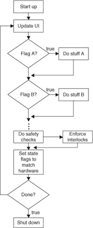
Figure 2.4: A typical tight-loop, switched operating design.
We can make this design pattern more flexible with dynamic scheduling. In Fig. 2.5, we replace the fixed switch code order with a tasking process that acts on a sequential list of scheduled events. On each pass, a new event is pulled from the list and the queue trimmed (or a pointer advanced). Switching code processes each active event; this code executes one or more subroutines to handle the event and perform requisite functions. Interaction between task threads can still include semaphore flags; however, these tasks flags can also modify the queue by adding, subtracting, or resequencing upcoming event requests.
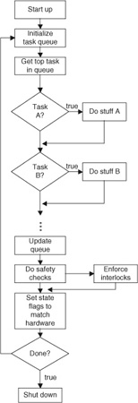
Figure 2.5: A typical tight-loop, queued operating design.
Note that including parameters for the queued tasks in the same data structure is only a small addition, so that the system can vary details of scheduled events. One of these parameters may even be an execution start time, so that events are delayed and left on the queue until a system timer value exceeds the passed parameter. Depending upon implementation, the “update queue” process may be as simple as advancing a pointer or clearing the top item; however, it might also include a quick sorting operation that tests requested execution times of newly added items and ensures proper priority sequencing.
In practice, the actual switching code will depend on the programming language and the processor: It may be a switch statement, it may be a list of conditional tests, or it may be a jump to an executable memory location. This detail is not important to the design pattern.
Scheduled events will typically include most operational tasks. Interactions can be quite complex: One event may schedule another event, change operational parameters, or remove one or more events from the queue. Note that one can easily schedule and queue some of the same tasks that are in the round-robin test list—taking advantage of the independent encapsulated code to handle both cases.
This brings us directly to the applicability of this design pattern in mission- and safety-critical systems. As shown in the figures, the fixed round-robin event section is a natural place to embed safety checks and interlocks. They are always executed, on each loop, no matter what task is processed from the queue. However, nothing prevents a designer from calling one of these safety checks, interlocks, or other operations within the operational code during a queued task. This permits re-application of heavily tested safety-critical routines that have been established early in the design process. It provides redundancy at the level of code reuse as well as critical crosscheck redundancy at the level of system operation. Memory overhead is minimal since critical code is encapsulated in subroutines. Reviewers can check each task for safety steps and separately confirm that the main loop always contains backups.
If one considers the scheduled events to be ordinary operational processes, it becomes natural to look at fixed round-robin tasks, such as safety checks and hardware state verification, as the equivalent of “interrupts” in a more advanced operating system. These conditions are tested on every loop with finite time latency. If true, they are acted upon. As with true hardware interrupts, good design dictates that these fixed events are quickly executed to minimize delays before returning to ordinary system interaction.
In some cases, rather than executing a long subroutine, a fixed event might instead test a hardware condition and then queue an appropriate action event to process the information through ordinary scheduling. Judgment must be made as to where to encapsulate the safety-critical actions, making sure to include those subroutines in the critical path testing, verification, and freezing process during development.
This section is intended to provide guidance on how one might incorporate fail-safe design patterns, even in very basic, homegrown embedded software. If your embedded system incorporates an O/S that already provides much of the event-handling architecture, the key failsafe ideas of encapsulated independence and redundancy should be retained and adapted to that structure. The choice of whether to rely on such solutions or to turn to a full-blown RTOS that handles deterministic queuing and multithreading is up to the engineer.
6. Hardware as Software: A Thought Exercise in Crossover Thinking
Both hardware and software engineers can benefit from crossover thinking when it comes to failsafe software design. Let us consider the microwave oven as a tangible example. We will start by considering the hazards and failure modes, look at how they are typically addressed in hardware, and then, as an exercise, consider how we would mimic the hardware design in solid traceable software. One would never fully eliminate hardware interlocks in a production appliance, simply because hardware can always fail in a manner that is undetectable in software. However, this thought exercise illustrates good practices in design that can be applied where software is required to play a major role in a mission-critical system.
First, let us carry out an abbreviated risk analysis of our basic microwave oven.

In addition, our usability requirements will include deciding under what conditions to allow the operations control logic to operate, and when to make an error condition apparent to the user so that it may be resolved.
Figure 2.6 illustrates a realistic hardware circuit that addresses the failure modes above. It is somewhat simplified for this discussion, but you will find that ovens in many kitchens comply with this basic model.
In brief, a fuse and two thermal protection devices cover the “low” and “moderate” risk-failure hazards by providing direct interruption of the primary line power to the device. Energizing the magnetron with the door open is an extremely high-risk failure and is addressed with redundant interlock systems.
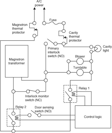
Figure 2.6: Typical schematic for hardware interlocks in a microwave oven.
The primary interlock switch is a mechanical door interlock that is open while the door is ajar. It prevents line power from reaching the magnetron transformer with the door open. Because it is possible that this switch could fail closed (perhaps due to age-related failure or simply dried food wedged in the wrong place), there is a second interlock monitor switch that shorts the transformer while the door is ajar. These two opposite acting physical switches provide primary protection against software errors, wiring shorts, physical abuse, and other significant failure modes.
It is possible, however, unlikely, that both of these switches might fail—one fused shut and the other stuck open. Low probability aside, the results would be very high hazard so the engineer has also incorporated a secondary interlock. This is accomplished with another, physically separate door-sensing switch. The sensing switch informs the control logic unit of the door state. In addition, relay 2, used by the control logic to energize the magnetron under proper conditions, is physically wired through this same switch, providing a final backup to software failure. Note the unabashed redundancy.
In ordinary operation of the oven, the control logic software, sensing the door ajar, disables keypad input so that (1) the start button cannot be activated and (2) the user has feedback that the oven will not function. Additional user feedback is provided by the cavity light, which remains lit until the door is closed. This provides an indication to the user as to why the keypad will not operate; more elaborate software might augment the door light by displaying “door ajar.” The error indication is clear and actionable.
There is significant redundancy built into this system. In fact, we could eliminate every mechanical switch but the door sensor and the basic features of the oven would operate correctly. Even though the boss might like to save a little money on switches, it is unlikely that a hardware engineer would be considered wasteful. The liability for a field failure is huge. Likewise the critical system software engineer should not look ill upon a few extra lines of code that add clarity and resilience to the design.
Note the labeling of the components. We consider the direct hardware interlock as the primary failsafe protection, and the ordinary operational sensor as the secondary system. Many software engineers not versed in mission-critical programming would address this system design in the opposite direction. That is, they would start at ordinary control operations, and then consider detection and notification of error states, and finally consider how to address failures outside their control. This forward approach is dangerous because the programmer cannot help but tacitly assume that his or her code will basically work correctly and that it can and will be fully tested and debugged. Yet forward thinking is entirely natural to the engineer because the control logic and the operational design features are the satisfying part of seeing a project come to fruition—the fun part of software.
Instead we make “safety first” our design approach. We give some real thought to “when all else fails,” even before spending much time on the “all else.” Then, with basic safety fallbacks in mind and set aside from the operational aspects of the project, we move ahead to the more challenging feature sets.
Let’s begin. We will build a basic code structure that mimics our microwave schematic while using principles of testability and encapsulation to isolate and control risks. For purposes of the exercise, we assume that we can replace each circuit-switching device with a software-controlled relay and a sensor. The schematic in Fig. 2.7 shows the idea. Each sensor can be read and each relay set directly by control logic via a simple applications programming interface (API).
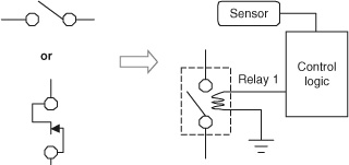
Figure 2.7: Imagine replacing each physical switch with a software-controlled sensor/relay combination.
Such APIs are typical and there is no sense dwelling on the bit-twiddling aspects of this example. More to the point, there should be no tolerance for propagating arcane code lines in a mission-critical project. So we begin by encapsulating our hardware operations in meaningful functions. In pseudo-code, our basic operations for the primary interlock system are:
PrimaryInterlockSensorDoorClosed()
if (primary interlock door detect sensor register) = true then
return true
else
return false
endif
to read the primary interlock door sensor,
PrimaryInterlockRelayClosed()
if (test primary interlock switch state) = (closed) then
return true
else
return false
endif
to check the primary interlock switch relay status,
SetPrimaryInterlockSwitch(setstate)
if setstate = true then
(set primary interlock switch closed)
wait (delay)
if PrimaryInterlockRelayClosed() = true then
return true
else
return false
endif
else
(set primary interlock switch open)
wait (delay)
if PrimaryInterlockRelayClosed() = false then
return true
else
return false
endif
endif
and to set the primary interlock switch. Similarly we can define other basic operations. These are simply listed in the following:
SetInterlockMonitorSwitch(setstate)
To control the interlock monitor switch
DoorSensorDoorClosed()
To read the secondary door sensor
SecondaryInterlockRelayClosed()
To check the door sensor relay switch status
SetSecondaryInterlockSwitch()
To control the door sensor relay switch
SetMagnetronEnergizeSwitch(setstate)
To control the Magnetron relay 2
The exact naming is not critical, but we emphasize clarity. Here we have used basic camel-back notation to label each function in long form with a meaningful name. Moreover, the name clearly defines what the stated response means, so we need not resort to poring over the documentation every time we call a function. A conditional of the form,
if DoorSensorDoorClosed() then
Do the right thing
else
Make a fuss
endif
is clear at a glance. Functions become methods in object-oriented languages, and will look a little different. Those who prefer typed variable-naming conventions will create even longer names. Regardless, the meaning should be transparent to you, to your code reviewer, and to whoever is gifted with the task of maintaining your code two years from now.
Each of these base-level routines can be tested in isolation to verify proper operation. For example:
PrimaryInterlockDoorTest()
do
If PrimaryInterlockSensorDoorClosed() the
(report door closed)
else
(report door open)
endif
loop
This trivial code allows basic testing to ensure that the door sensor is reading the door position correctly. As part of a verification plan, simple programs may be designed to exercise each low-level hardware routine while asking the tester to change the door state and record results. This auxiliary code is the equivalent of a test harness in the hardware world. Again, encapsulation lies at the heart of the “design-for-test” concept.
We can encapsulate the primary interlock system operation as follows:
PrimaryInterlockCheck()
if PrimaryInterlockSensorDoorClosed() then
switchOk = SetPrimaryInterlockSwitch (true)
if switchOk = false then
trap hardwareerror
endif
switchOk = SetInterlockMonitorSwitch (false)
if switchOk = false then
trap hardwareerror
endif
else
switchOk = SetPrimaryInterlockSwitch (false)
if switchOk = false then
trap hardwareerror
endif
switchOk = SetInterlockMonitorSwitch (true)
if switchOk = false then
trap hardware error
endif
endif
The function returns true if the door interlock switch is properly closed, and false if it is not. Physical interlock switches are set appropriately. If physical hardware fails to respond in a verifiable way, the routine does not return at all; rather it executes special-purpose error handling code.
The line “trap hardware error” is shorthand for abandoning ordinary operation in favor of a catchall operation that takes care of detectable hardware failures. This is sometimes called “throwing an exception,” developed further in discussion on “Exception Handling” later. In a safety-critical system, this will generally result in an attempt to return everything as quickly as possible to a known safe state.
Every time this function is executed, the system tests the interlock sensor and sets the two control switches appropriate to the door state. Now we ask the question, how often do we execute this? Remember, the door itself is outside your control. Your practical options depend on your O/S and processor. Three options in decreasing order of desirability are considered:
Interrupt Driven: This critical operation is an obvious candidate for a hardware interrupt. If the primary interlock door sensor–state change can trigger a hardware interrupt, then PrimaryInterlockCheck() can be executed at each interrupt to change the relay states.
Schedule Driven: If the O/S supports multithread or scheduled execution, then PrimaryInterlockCheck() can be executed periodically on an independent thread from the primary operations software. “Periodically” must mean frequently enough to provide protection; hence, in this case, it will likely be on the order of no more than a few milliseconds between loops.
Main Loop: In very basic microprocessors, for simple tasks, one often relies on a tight main loop that tracks and triggers other operations. In this case, we would include the code:
do
PrimaryInterlockCheck()
query keypad
. . .
do otherstuff
. . .
loop until shutdown
The third method is common in “roll-your-own” real-time designs. We consider this common design pattern further in section 5. It is risky, in that any glitch or bug in the “otherstuff” could freeze or delay the main loop, causing a safety hazard. This choice should be coupled with very careful version control, since any modification to the code that results in a new bug could create a severe safety hazard.
If forced to use method three, one should immediately consider other places to add redundancy. For example, one presumes that somewhere in “otherstuff,” there will appear commands to turn on the magnetron; if available code space allows an extra call to PrimaryInterlockCheck(), why not be safe?
Independence is key: Safety critical functions should be designed, tested, and executed independently of control operations code.
Methods 1 and 2 have the advantage, in that they will better survive code changes and new bugs in the operational code. They are by no means immune from the software failure modes and should also include strategic redundancy. However, with method 3, we are simulating periodic interrupts; hence adding redundant checks at other frequented portions of the control code should be considered, particularly where you expect longer latency. Function over form in this case, as safety is never inelegant. For a personal example, see Example 2.4.
Keep in mind that this is a thought exercise and there is a fourth method, illustrated by the original schematic diagram: analog hardware. No software engineer should consider his or her system beyond fallibility and, in practice, one would not recommend implementing this or any safety-critical system without hardware interlock redundancy. Every critical-system software engineer should study the Therac-25 radiation therapy device failure (see Example 2.8) as inspiration.
Moving down the safety ladder, let us consider the secondary interlock system:
SecondaryInterlockCheck()
if DoorSensorDoorClosed() then
switchOk = SetSecondaryInterlockSwitch (true)
if switchOk = false then
trap hardwareerror
endif
else
switchOk = SetSecondaryInterlockSwitch (false)
if switchOk = false then
trap hardwareerror
endif
endif
As with the first interlock check, it makes sense to run this secondary code frequently in an interrupt-driven fashion or a scheduled thread. If we do not have that option, then, again, redundancy doesn’t hurt. For example, we might write simple code to start cooking as follows:
TurnOnMagnetron()
PrimaryInterlockCheck()
SecondaryInterlockCheck()
if DoorSensorDoorClosed() then
SwitchOK = SetMagnetronEnergizeSwitch(true)
if switchOk = false then
trap hardwareerror
endif
magnetronActive = true
else
magnetronActive = false
endif
As used here, magnetronActive is a state variable. This could correspond to a global variable in function-based code, or a property of the Magnetron class object in an OO language like C++. It provides convenience for our control code, allowing us to determine the state where we think that we’ve placed the Magnetron. In fact, using the principles we have established, it would be better to make magnetronActive a function that actually tests the state of the magnetron. In this fashion, there is no way we could mislead ourselves into believing that the magnetron is energized when it is off, or (worse!) that it is off when in fact it is energized. Assuming that our hardware allows us to read back the register that controls relay 2, we can improve our design.
MagnetronActive()
if (test magnetron switch state) = (closed) then
return true
else
return false
endif
Even better would be to get independent secondary information, such as a direct measurement of current to the magnetron or direct detection of microwaves.
Example 2.8. The Therac-25 Nightmare
The Therac-25 radiation therapy debacle has become a standard case study in failure modes of software-based safety-critical systems. Between 1985 and 1987, multiple patients were given radiation doses roughly 100 times higher than intended as a result of an undiscovered software bug. At least six of these overdoses are known to have resulted in severe radiation poisoning and three of the patients eventually died.
This therapy system was feature-rich, with multiple distinct operating modes. In particular, the machine was able to deliver either short-duration direct electron-beam therapy or diffuse x-ray therapy. In order to produce x-rays, the system used the same electron beam at high energy directed against an emitting target. Radiation therapy devices represent an enormous capital investment and this was a clever engineering idea to maximize available treatment options within a single unit. Secondary mechanisms were used to diffuse and collimate the beam to achieve properly controlled dosing for each mode.
The two operation modes required that diverse components be physically moved into and out of the beam path by mechanical actuation. Open-loop control was used to configure the mechanical components. Eventually, a hidden software bug emerged: when certain atypical user-interface entry sequences were made, the unit was temporarily misconfigured, sometimes resulting in a high power beam directed at the patient without being diffused to safe levels.
The Therac-25 software failed to verify hardware conditions. In fact, it has been reported that the open-loop control code had been retained from previous system designs in which hardware interlocks prevented such malfunctions; however, there were no hardware interlocks in the Therac-25. The problem triggered large-scale rethinking of the role of software and software process in safety-critical systems.
Not only was code inappropriately reapplied, the overall architecture was glued together in a way that made contextual verification very difficult. The designers probably relied on past field experience, unaware of having inherited hidden critical dependence on the hardware interlocks.
A chain of design failures contributed to the unsafe system, a list of which reads like a textbook nightmare example. Convenient features were prioritized compared to hazard analysis. The software was not independently reviewed. Borrowed code was reapplied without risk assessment. The hidden bug was triggered by rare keyboard entries, making detection in V&V unlikely and discovery and tracing in the field difficult. The machine detected irregularities in beam energy and shut down, but did so too slowly to protect the patient. Upon shutdown, only obscure alert codes were presented to the operator, offering no actionable information and encouraging complacency.
Each design failure compounded the others and, in not following good practices, the resulting system was not failsafe, user tolerant, nor engineering-flaw robust.
Numerous detailed reviews of the Therac-25 experience have been published, and we strongly encourage the reader to locate a few of them to help drive home the importance of good process and design strategies. A convenient summary with a list of references is available online at en.wikipedia.org/wiki/Therac-25 and en.wikipedia.org/wiki/List_of_software_bugs.
Verify reality: Avoid mirroring hardware in state variables when the state is directly testable. In some cases you are at the mercy of the hardware or the physical system. The goal of the mission-critical software engineer, however, should be to ascertain and verify the actual state of the physical hardware insofar as possible so that critical decisions are not made on faulty assumptions.
Following similar patterns, we can write straightforward code to test thermal conditions. For example,
MagnetronTempCheck()
if GetMagnetronTemperature() > 135c then
SwitchOK = SetMagnetronThermalSwitch(false)
if switchOk = false then
trap hardwareerror
endif
return false
else
SwitchOK = SetMagnetronThermalSwitch(true)
if switchOk = false then
trap hardwareerror
endif
return true
endif
Similarly, we can create a CavityTempCheck() function.
Leaving power surges and shorts to the good old hardware fuse, we now have four scheduled tasks to keep track of our safety state. We can bundle them for convenience:
SafetyStateCheck()
PrimaryInterlockCheck()
SecondaryInterlockCheck()
MagnetronTempCheck()
CavityTempCheck()
Finally, we can provide an encapsulated crosscheck routine that quickly verifies the state of all hardware and sensors so that the operational code can remain coupled to the state of the hardware and does not rely entirely on state variables.
SafeToOperate()
If PrimaryInterlockSensorDoorClosed() and
DoorSensorDoorClosed() and
PrimaryInterlockRelayClosed() and
SecondaryInterlockRelayClosed() and
GetMagnetronTemperature() < 135 and
GetCavityTemperature() < 120 then
return true
else
return false
endif
Note what we have achieved. We have clearly named functions that perform our safety checks, bundled outside of the main control code so that they can be individually tested and readily verified by visual inspection in code review. Requirements generated by the hazard analysis are directly traceable to code.
Each function takes care of ensuring safety internally. Certain safety checks may return a status flag to the calling routine for purposes of notifying operating software that it is okay to continue to interact with the user. However, the actual safety of the system is not jeopardized even if these flags are ignored.
Now, with our safety-critical elements bundled, we can turn to implementing the control code. To keep things simple, let us assume this microwave oven has only one button: 60-second heat. Two mission-critical requirements emerge, one of which overlaps with our safety checks. These are:
1. Cook as close as possible to 60 seconds.
2. Interrupt if the door is opened.
Let us assume for maximum programmer hardship that we do not have interrupt or thread-based O/S support. We might code this sequentially as follows for our cooking checks first:
CookingChecks()
timerCnt = timerCnt—1
if timerCnt = 0 then
TurnOffMagnetron()
if MagnetronActive then
PanicOff()
endif
endif
if DoorSensorDoorClosed() = false then
TurnOffMagnetron()
if MagnetronActive then
PanicOff()
endif
endif
Note we have put a direct crosscheck on the state of the magnetron. If it fails to go off when requested, we execute a panic routine that attempts to force the system to a known safe state. This is discussed further when we get to exception handling.
Next we code our tiny user interface:
ButtonCheck()
if (button pushed) then
SoundKeyPressBeep()
TimerCnt = 60 (time factor)
SafetyStateCheck()
If SafeToOperate() then
TurnOnMagnetron()
else
(complain to user)
endif
endif
“Complain to the user” in a simple system could be just a feedback beep that differs from the key-press sound, or could be a flashing error message. If the hardware allows, then longer explanations are more desirable. However, in the event of a dangerous condition out of keeping with expected events—such as a stuck relay or sensor—the designer should seriously consider disabling the interface in a manner that requires technician intervention. This would prevent a frustrated user from ignoring the alarm and possibly escalating the alarm condition into a situation that compromises safety.
Our main operation code is fairly simple:
Main ()
If SelfTestEmbeddedCodeOK() = false then
(complain to user)
end execution
endif
If SelfTestHardwareOK() = false then
(complain to user)
end execution
endif
SetInitialHardwareState()
do
SafetyStateCheck()
if MagnetronActive then
If SafeToOperate() then
CookingChecks()
else
PanicOff()
endif
else
if DoorSensorDoorClosed() then
CavityLightOff()
ButtonCheck()
else
CavityLightOn()
endif
endif
loop
On cold re-start, the system first established that the software is uncompromised and that each testable hardware component and register responds properly—taking care, of course, not to exercise components during self-tests in any way that could itself compromise safety. Once we verify the system, we set initial hardware states and enter the main execution loop. Since this is an always-ready cooking appliance, there is no need for an explicit shut-down. That will occur either when the plug is pulled or an exception is detected.
We began with the safety-critical elements and then constructed the operational code. Note that we reused hardware status tests both in the safety-critical code and in the operational segments, simplifying implementation. We also make safety check calls at each level of the code, sometimes redundantly in the sense that we make similar checks at different code levels that might, when unwound, result in duplication in the sequence of events.
However, the duplication involves only the re-execution of tiny code segments and will not detract noticeably from response feel. Advantages include easy review of the code, since safety steps are visible at a glance at each level. Failure modes in our RA/HA chart can be mapped directly to independent, encapsulated code during critical safety reviews, while operational code can be verified against design operating sequences without nervously working through possible safety compromises at every software update. The redundancy also provides protection against future bugs introduced in the operational code and even some parts of the critical code segments.
Finally, a note on exception handling: In aviation, pilots have a general mnemonic phrase to keep priorities straight during emergencies. The phrase is, “Aviate, navigate, communicate.” The same principles apply to an emergency situation in a critical-system design.
When something goes wrong, priority one is to get the operation of the system under control and into a known safe state. The first step in this example would be to execute a PanicOff() operation. In practice, the difference between ordinary “off” routines and the panic routine comes down to assumptions about hardware compliance. The detected failure could represent a transient symptom of an intermittent hardware issue. Rather than simply shutting down the magnetron by the usual means, it is advisable to issue API commands multiple times to each available interlock switch. Do so in a loop that tests for compliance and tests sensors for verification.
Once the hardware is safe, then attempt to sort out the device status and whether it is safe to do anything other than remain shut down. Next, communicate the situation to the user.
If the shut-down loop times out without reaching a verified safe state, take all reasonable measures to otherwise shut down the system. Carefully consider this use case during design of the safety-critical elements: How long should you wait to notify the user? How can you notify the user clearly and effectively to achieve desired action? Generally your software can act far faster than any user can react; however, there are circumstances, such as precautionary personnel evacuation, where it will be advisable to sound the alarm in advance of trying to solve the problem and then communicate details later. Obviously, if active user intervention is required, notification then becomes the safety shut-down step.
Again, this thought exercise is not intended to show useful design patterns. It is not intended to be realistic, as one would never produce a microwave oven or any other dangerous physical device without including additional layers of hardware interlocks. Our purpose is to try to connect safety-first, failsafe redundant hardware engineering practices to similar possible practices in software.
Example 2.9. Telephone Tag
What about that perpetual “new call” light in my kitchen? I’ve never seen the firmware for my wall phone, but I’d wager a week of Venté Mochas that the error is conceptually similar to that described in Example 2.4. A state variable of some sort (perhaps simply the register that controls the light) is intended to mirror reality. When it gets out of synch with reality, there is no periodic verification, and hence, in contrast to the brain stimulator, there is no automatic means of correcting the problem. Fortunately, this is not a mission-critical function of the phone; it is merely annoying.
A few years of sporadic test data reveal that the stuck “new call” light often occurs when the phone ring is interrupted before an incoming caller ID code is fully processed.
Let us fix these ideas with an example. Consider a block of code triggered by the ringing phone:
OnRing()
...
setNewCallLight
start RingerSound Thread
start GetCallerID Thread
...
and somewhere in the GetCallerID thread code:
getInComingCallerID()
...
do until last byte received
get data
accumulate CallIDstring
if waitTimeOut then
return “No Caller ID Available”
endif
...
loop
...
addCallerIDtoCallList(CallIDstring)
newCallCount = newCallCount + 1
return CallIDstring
Most of the time the phone will ring and a fully processed result will be added to the call list. On this assumption, the engineer probably delegates clearing of the “new call” light to the call review operation: each time a call is viewed in the list, the individual “new” flag is cleared and the newCallCount is decremented. If newCallCount hits zero, then the clearNewCallLight is executed. However, if the newCallCount = 0 already, then clearNewCallLight is never executed. A classic coding error is to use too specific a conditional:
...
newCallCount = newCallCount−1
if newCallCount = 0 then
clearNewCallLight
endif
...
The problem, of course, is that if newCallCount = 0 already, then the decrement (depending upon the arithmetic type) either takes the counter negative or wraps to the highest possible integer. With all individual “new” flags cleared, the counter is now misaligned with the actual number of new calls, and the counter light will likely never be cleared no matter how many times we cycle through the review list.
How could this happen? Caller ID is generally transmitted over the beginning of the first ring period; if it is possible to pick up the phone or otherwise interrupt the process between turning on the “new call” light and incrementing the newCallCount, then we will have triggered the intermittent bug.
This is only one concocted scenario and there are ample other possibilities. Perhaps the “new call” light-circuit switch simply intermittently fails to respond and the code never revisits turning off the light once the internal state reflects an off condition. We can be sure that it is not a pure hardware error, such as a stuck gate, since clearing all calls from memory with a “soft reset” reliably switches off the light.
It does not so much matter what is failing—an interrupted firmware thread, or a slightly sticky bit. Ultimately, the engineer has made an assumption that the state of the light will always remain in synch and has failed to subsequently verify reality in the code.
Defensive programming possibilities abound: forcing the indicator light and program state to synchronize at any regular point in the phone operation could have easily provided a catchall check. Certainly the user expects the new call light to go out when all calls are cleared. Why not make a quick count of “new” call flags in the list as the software is leaving “call review” mode, and simply force the light “off” whenever that count comes up zero? Perhaps that is too time consuming for the tiny embedded processor; then why not at least force the light “off” when the user scrolls back to call number #1 in the review list? If the user has reviewed all the calls in the list, then he or she has obviously seen them all.
This is a benign example of where good coding practices could improve the user experience. Obviously, our curmudgeonly light is not safety sensitive, nor is it mission critical to the operation of the telephone. But it certainly was not the intent of the architect to force phone users to exercise the soft reset—deleting all incoming call records—on a regular basis. Lack of redundancy and lack of provability led to a low-occurrence failure mode that escaped testing. By providing independent secondary code elements as a matter of course one can easily design in low-overhead redundancy that ensures a reliable user experience.
7. Conclusions
We discussed three principles that drive all aspects of the critical-system development process that persist through design, implementation, and testing. Our ultimate goal is the last of these: provability. To achieve it we need to carefully apply the other two, and broaden our view with respect to how we think about failure modes, how we think about the fallibility of our system components, and how we think about the fallibility of human designers.
The second principle, redundancy, like the second law of thermodynamics, is perhaps the most significant in obtaining useful results. Strategic redundancy at all stages of the design process and in the code architecture underlies consistently successful critical-system development.
Critical-safety functions should be designed, tested, encapsulated, and executed independently of control operations code insofar as possible. Design these elements first, begin with a carefully thought-out RA/HA matrix that includes hardware, environmental, software, and user-associated risks. Verify the critical backbone subsystems independently before focusing on integration with operational code. To the extent possible, meet specific needs with specific, traceable code. Think of it as defensive programming.
Where possible, always design systems to verify reality: avoid open-loop designs and mirroring hardware with state variables when the physical state is directly measurable. Consider the user and the user interface in terms of how they affect the mission risks and establish explicit use cases; make sure that information conveyed is necessary, clear, and actionable and that feature creep does not overrun function.
Even non-critical embedded systems can benefit from some of these design patterns. All embedded software has a mission; predictably, achieving that mission is what makes a good-quality product. (My kitchen phone still insists I have a new call.)
Failsafe software design means acknowledging a broad spectrum of downside threats and possibilities and carefully bounding the risks. No human engineered system is inherently infallible and we should not design systems on the expectation that we can make them so. Instead we can engineer for anticipated failure modes insofar as possible and for unanticipated failure modes through built-in redundancy and safety factors. By taking considered steps and exercising good practices, we can create critical systems that are robust to physical component failures and unplanned situations, highly user tolerant, and even forgiving of the system’s own potential hidden flaws.