It’s all in the detail. And attention to detail is key to successful design and delivery of quality homes. Lack of attention to detail leads to critical errors that affect the performance of new homes. This book is an attempt to rectify some of these performance issues to help designers and contractors reduce this performance and quality gap so that we can consistently deliver better homes.
Better homes have low energy use, good thermal comfort and excellent indoor air quality. Studies by the Zero Carbon Hub, Innovate UK and others show that the majority of newly built homes are failing to meet their required performance. The underlying reason for this failure is that energy efficiency, comfort and indoor air quality are difficult to check.
The home buyer cannot see the quality of the inner construction, elements that directly influence their heating bills, indoor air quality and comfort. Thermal performance is unlikely to attract customers and therefore it is not high on the list for housebuilders to engage with. All of the 300 homes in the Zero Carbon Hub inspections (2012–2016) and Innovate UK BPE study (2016) failed to meet their intended performance when tested. The majority were short of Part L and Part F of the Building Regulations by a significant margin (50% or more).
Common failings uncovered in this study are highlighted in the Builders’ Book, Services Guide and the Thermal Bridging Guide (Zero Carbon Hub 2016) and include unaccounted thermal bridging, thermal bypass, uncontrolled air leakage and poorly designed, installed and commissioned building services. The evidence showed many minor errors that have a significant impact on performance. An example is shown in Figures 0.1 and 0.2, where the installation of the window differed by 50 mm and reduced the performance of the junction by 140%.1
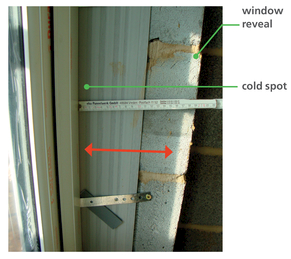
Figure 0.1
No overlap of window and cavity creates a thermal bridge (below left).
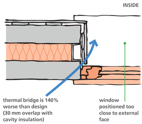
Figure 0.2
Thermal bridge example2 (below right).
The combined result of these failures is poorly performing homes. This book highlights such common failings and offers solutions for design and construction of homes that do what they should be doing: providing a low-energy, healthy environment to live in.
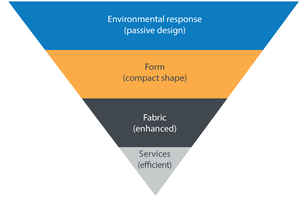
Figure 0.3
Energy performance hierarchy.
The energy performance hierarchy (Figure 0.3) illustrates that orientation and form have the largest impact on the performance of a home and are determined by a range of factors to meet the brief and function. Form responds to environmental context, but this is normally secondary to other planning considerations such as height, density, house type, vernacular style and design constraints such as existing roads, buildings, noise sources and conservation areas. As the form is normally decided according to these site-specific constraints, this book focuses on making improvements to the last two parts of the performance hierarchy – fabric and services, which are common to all new homes. This is where the largest performance gap lies, and where the largest improvements can be made.
Chapter 1 examines the gap between design and as-built performance and highlights common areas that designers and builders need to engage with. It also takes a strategic view on ways industry and government can improve the performance of new-build housing. Chapter 2 describes current performance standards, and the principles of a thermally efficient building envelope. It summarises good practice, detailing principles applicable to all construction methods.
Chapters 3 to 7 highlight different construction types common for new homes and key areas of the thermal envelope that often are problematic. The drawings show potential solutions that will help designers and contractors improve the performance. These chapters look at each construction fabric in turn, starting with the most common in the UK and finishing with the least common yet more innovative methods.
All photos were taken by the author on live construction sites except where noted. The detail drawings of good practice show a fabric-first approach that meets and exceeds Part L 2016 of the Building Regulations and is likely to comply with future versions of Part L and higher standards such as Passivhaus and zero-energy buildings. All details have been built and checked for buildability and compliance on site. Some of the details are compatible with the Passivhaus standard and have been noted as such. The diagrams can directly inform the architect’s own detail drawings of the building envelope. The construction principles in this book will be valuable to all those who are seeking to design better performing thermal envelopes. In particular it addresses thermal bridging, thermal bypass, airtightness, buildability and site issues.
Applying the principles of reduced thermal bridging and improved airtightness to all elements of the building will significantly reduce the heat demand, associated heating bills and overall CO2 emissions. The book highlights the typical construction junctions and typical performance given in U-values and psi-values. The psi-values have made standard assumptions for the thermal resistance of materials, which are stated in Appendix 3.


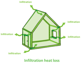
Figure 0.4
U-values, psi-values and infiltration combine to give the total heat loss of a dwelling.
Key details have been modelled in thermal bridging software to ensure minimal heat loss at the junctions and to provide a psi-value to aid designers in energy calculations (SAP). For use in SAP calculations, they should be recalculated with project-specific information. The psi-values have been calculated using THERM 7.4.3 for 2D and TRISCO 13.0 software for 3D models in accordance with BR 497. Figure 0.4 shows how U-values, psi-values and infiltration combine to give the total heat loss of a dwelling.
Chapter 8 examines the common mechanical and electrical services in new homes. The diagrams help improve the detailing and specification of new homes at construction stage, and also inform designers of services requirements at early stage design. Heating and ventilation systems that are not installed or commissioned correctly form a significant part of the performance gap.
Common examples of this poor design and installation of services are shown in Figures 0.5, 0.6 and 0.7 (see page 6). Chapter 8 highlights basic performance recommendations for key building services to deliver their intended performance.
Chapter 9 concludes the book with a summary of how to deliver improved performance for new homes. Designers, contractors, policy makers and clients all have significant roles to play in improving the quality of new-build homes, and this chapter offers some recommendations for improvement.
Chapter 10 examines the common mechanical and electrical services in new homes. The diagrams help architects to improve their detailing and specification at construction stage, and also inform concept designers of services requirements at early stage design. The building services in new homes commonly fail to meet Building Regulations, in particular the heating and ventilation systems that are being installed incorrectly and not commissioned.3
The Appendices include checklists for both designers and contractors based on the RIBA Plan of Work and traditional build sequencing. These checklists are project management tools, and should be adapted to suit individual project requirements and construction methods. It is hoped this book will offer some practical guidance to help professional, client and contractor teams improve the design and construction quality of new homes.
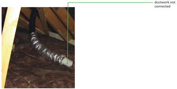
Figure 0.5
Poorly installed ventilation ductwork in loft space (left).
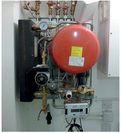
Figure 0.6
Uninsulated, poorly installed heat interface unit (HIU) (right).
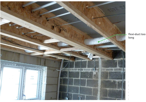
Figure 0.7
Flexi-duct too long and not supported means that fans will be noisy and inefficient.