2
Microgrids Control Issues
2.1 Introduction
The notion of control is central in microgrids. In fact, what distinguishes a microgrid from a distribution system with distributed energy resources is exactly the capability of their control, so that they appear to the upstream network as a controlled, coordinated unit [1,2]. Primary control of DER is discussed in Chapter 3. This chapter focuses on secondary control or energy management issues [3]. Effective energy management within microgrids is a key to achieving vital efficiency benefits by optimizing production and consumption of heat, gas and electricity. It should be kept in mind, that the microgrid is called to operate within an energy market environment probably coordinated by an energy service provider/company (ESCO), who will act as an aggregator of various distributed sources and probably a number of microgrids.
The coordinated control of a large number of DERs can be achieved by various techniques, ranging from a basically centralized control approach to a fully decentralized approach, depending on the share of responsibilities assumed by a central controller and the local controllers of the distributed generators and flexible loads. In particular, control with limited communication and computing facilities is a challenging problem favoring the adoption of decentralized techniques. Complexity is increased by the large number of distributed resources and the possible conflicting requirements of their owners. The scope of this chapter is to present an overview of the technical solutions regarding the implementation of control functionalities. Thus, not only the electrical operation will be presented but also issues regarding the ICT challenges.
2.2 Control Functions
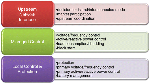
Before analyzing the technical implementation of control, a general overview of the main control functionalities in a microgrid is presented. These functionalities can be distinguished in three groups, as shown in Figure 2.1. The lower level is closely related to the individual components and local control (micro sources, storage, loads and electronic interfaces), the medium level to the overall microgrid control and the upper level to the interface to the upstream network.
Figure 2.1 Overall system functionalities
More specifically:
Upstream network interface
The core interaction with the upstream network is related to market participation, more specifically the microgrid actions to import or export energy following the decisions of the ESCO. Owing to the relatively small size of a microgrid, the ESCO can manage a larger number of microgrids, in order to maximize its profit and provide ancillary services to the upstream network. The operation of multi-microgrids is discussed in Chapter 5.
Internal microgrid control
This level includes all the functionalities within the microgrid that require the collaboration of more than two actors. Functions within this level are:
- load and RES forecast,
- load shedding/management,
- unit commitment/dispatch,
- secondary voltage/frequency control,
- secondary active/reactive power control,
- security monitoring,
- black start.
Local control
This level includes all the functionalities that are local and performed by a single DG, storage or controllable load, that is:
- protection functions,
- primary voltage/frequency control,
- primary active/reactive power control,
- battery management.
It should be noted that these functionalities are relevant to the normal state of operation. They might need to change in critical or emergency states, as discussed in Chapter 5.
Chapter 2 focuses on internal microgrid control (management) in the normal state of operation. The normal state covers both islanded and interconnected mode and does not deal with transition to island mode. The role of information and communication technology is critical for the relevant control functions.
2.3 The Role of Information and Communication Technology
Information and communication technology (ICT) is a critical component of future power networks. Beyond any doubt, the control and operation of the future power grids, including microgrids, needs to be supported by sophisticated information systems (ISs) and advanced communication networks. Currently, several technologies have been used or tested at distribution systems and it is expected that their usage will become more extensive during the coming years. The usual approach is to use existing solutions as a starting point, in order to develop new applications for microgrids. The main technological areas are as follows:
Microprocessors
Modern microprocessors are utilized extensively within microgrids providing the ability to develop sophisticated inverters and to develop load controllers or other active components within microgrids. An interesting characteristic of the new version of microprocessors is that they provide adequate processing power, communication capabilities and sophisticated software-middleware at low prices.
Communication
The past decade has been characterized by developments in communication networks and systems. These networks provide sufficient bandwidth and can offer several services to the users. It is obvious that active control of microgrids will be based on existing communication infrastructures, in order to reduce the cost.
Software
Service oriented architectures (SOA) is the modern trend in building information systems. The core of this approach is the web service. The W3C (World Wide Web Consortium [4]) defines a “web service” as “a software system designed to support interoperable machine-to-machine interaction over a network”. There are many definitions of the concept of SOA. For the purpose of this chapter an SOA is defined as a set of web services properly organized in multiple layers, capable of solving a set of complex problems.
The internet of energy
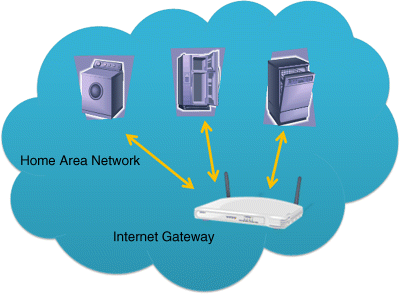
The internet of energy is the usage of technologies, developed for the world wide web, that allows avoiding installation and maintenance costs of dedicated devices for the control of DGs and loads. With this approach, all the applications for household control could take the form of a piece of software running on a device with processing capabilities: a smart TV or the internet gateway, for example. It is also assumed that the next generation of home appliance will be equipped with the necessary interfaces to allow remote access via the home area network (Figure 2.2).
Figure 2.2 The smart home
A significant part of the necessary technology already exists: internet gateways, IPv6, embedded processors, smart phones, corresponding operating systems and so on. Furthermore, several houses nowadays are quite automated, using advanced sets of home cinemas with internet connection, advanced wireless alarm systems, central automated air-conditioning systems and so on.
2.4 Microgrid Control Architecture
2.4.1 Hierarchical Control Levels
There is no general structure of microgrid control architecture, since the configuration depends on the type of microgrid or the existing infrastructure. Before analyzing the microgrid control and management architecture, let's have a look at today's distribution systems. Figure 2.3 presents the major parts of the control and management infrastructure of a typical distribution system with increased DG penetration. We can distinguish the distribution management system (DMS) and the automated meter reading (AMR) systems. The DMS is mainly responsible for the monitoring of the main HV/MV and maybe some critical MV/LV substations. The hardware system consists of the main server and several remote terminal units (RTUs) or intelligent electronic devices (IEDs) spread across the distribution system. Usually the DMS does not control the DGs/RESs (except for some large installations in certain cases) or the loads. Typical control actions are network reconfiguration, by switching operations in the main feeders, and voltage control via capacitor switching or perhaps transformer tap changing (mostly manually). The AMR system is responsible for the collection of electronic meter readings and is used mainly for billing purposes. In Figure 2.3, we do not consider the existence of the advanced meter infrastructure (AMI), since this is considered next, as part of the microgrid control system. By AMI, we also mean the capability of controlling some loads locally, either directly via the meter or via the home area network, in which case the electronic meter is the gateway.
Figure 2.3 Typical distribution system management structure
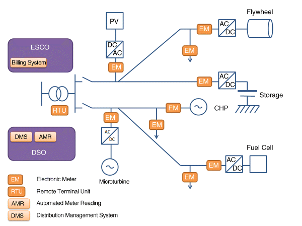
As discussed in Section 1.5.1 the DSO is responsible for managing and controlling the distribution system and is also responsible for collecting the energy metering data, although in some countries meter reading can be handled by an independent entity. The DSO sends the metering data to the supplier/ESCO, who is a market player and is responsible among other things for the billing of customers.
The structure shown in Figure 2.3 is not sufficient for microgrid management, since it provides limited control capabilities, especially within a market environment. Thus, it is important to introduce a new control level locally at DG and loads, capable of meeting the goals of
- enabling all relevant actors to advanced market participation
- being scalable in order to allow the integration of a large number of users (scalability)
- allowing integration of the components of different vendors (open architecture)
- ease of installing new components (plug-and-play)
- ease of integrating new functionalities and business cases (expandability).
Using the local control level, a more complicated, hierarchical architecture is introduced in Figure 2.4. This architecture comprises the following:
Figure 2.4 Typical microgrid management structure
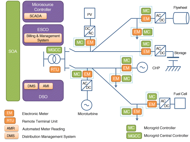
The microsource controller (MC) which is responsible for controlling and monitoring distributed energy resources, such as DGs, storage devices and loads, including electric vehicles. The MC could be a separate hardware device or piece of software installed in either the electronic meter, the DG power electronic interface or any device in the field with sufficient processing capacity. This is shown as a dashed frame that surrounds both the MC and the EM.
The microgrid central controller (MGCC) provides the main interface between the microgrid and other actors such as the DSO or the ESCO, and can assume different roles, ranging from the main responsibility for the maximization of the microgrid value to simple coordination of the local MCs. It can provide setpoints for the MCs or simply monitor or supervise their operation. It is housed in the MV/LV substation and comprises a suite of software routines of various functionalities depending on its role.
The distribution management system (DMS), discussed previously, is responsible among others for the collaboration between the DSO, the ESCO and the microgrid operator. The existence of a backbone system, a platform, based on service oriented architecture is assumed for the integration of its functionalities. In some cases, the MGCC software can be integrated in this platform.
2.4.2 Microgrid Operators
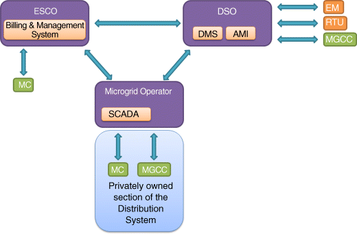
The microgrid operator, introduced in Section 1.5.1 can be further distinguished depending on the type of microgrid and the roles of the DSO and supplier/ESCO. The role of the DSO as a “flexibility facilitator” or “flexibility actor” is central in these distinctions. Based on Figure 2.4, three main general configurations, as presented in Figures 2.5–2.7 can be identified. It should be noted that the aim of these figures is to show the flow of information among actors and not to present microgrid business models.
- DSO as flexibility actor: The DSO controls the DER via the available infrastructure. The ESCO sends requests to the DSO and not directly to the field. This function is fully applicable in the DSO monopoly model of Section 1.5.2, but can be also relevant to the liberalized market model.
- DSO as flexibility facilitator: The supplier/ESCO installs separate control equipment in the field and directly manages at least some of the DER. There is close collaboration with the DSO. This function is fully applicable in the liberalized market model of Section 1.5.2.
- Dedicated microgrid operator: This is a special configuration suitable for an independent (privately owned) part of the distribution network, such as a mall or an airport. In this case, a dedicated microgrid operator can be responsible for the management of this part of the network. A typical case is the prosumer consortium model of Section 1.5.2.
Figure 2.5 DSO as flexibility actor

Figure 2.6 DSO as flexibility facilitator

Figure 2.7 Dedicated microgrid operator
2.5 Centralized and Decentralized Control
The microgrid structure depicted in Figure 2.4 can be operated in a centralized or decentralized way, depending on the responsibilities assumed by the different control levels. In centralized control, the main responsibility for the maximization of the microgrid value and the optimization of its operation lies with the MGCC. The MGCC using market prices of electricity and gas costs, and based on grid security concerns and ancillary services requests by the DSO, determines the amount of power that the microgrid should import from the upstream distribution system, optimizing local production or consumption capabilities. The defined optimized operating scenario is realized by controlling the microsources and controllable loads within the microgrid by sending control signals to the field. In this framework, non-critical, flexible loads can be shed, when profitable. Furthermore, it is necessary to monitor the actual active and reactive power of the components. In a fully decentralized approach, the main responsibility is given to the MCs that compete or collaborate, to optimize their production, in order to satisfy the demand and probably provide the maximum possible export to the grid, taking into account current market prices. This approach is suitable in cases of different ownership of DERs, where several decisions should be taken locally, making centralized control very difficult. Apart from the main objectives and characteristics of the controlled microgrid, the choice between centralized and decentralized approaches for microgrid control, depends on the available or affordable resources: personnel and equipment. The two approaches are presented in Figures 2.8 and 2.9. In both approaches, some basic functions are centrally available, such as local production and demand forecasting and security monitoring.
Figure 2.8 Principles of centralized control
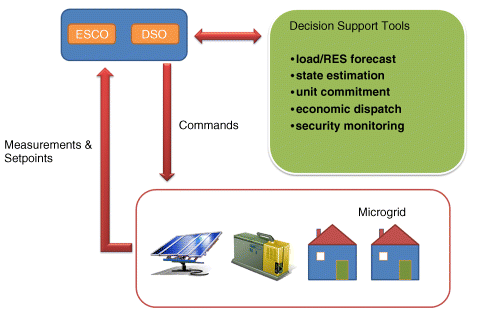
Figure 2.9 Principles of decentralized control
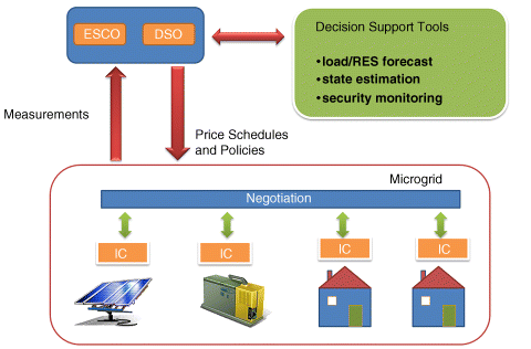
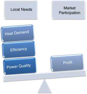
Figure 2.10 The control system should be able to balance between market participation and local needs
In this section, the effectiveness of the two approaches in terms of calculation time, scalability and accuracy is discussed. At this point, the introduction of algorithm complexity is useful. Algorithm complexity refers to the calculation time that an algorithm needs to finish a task. This calculation usually correlates the execution time needed with one or more arguments, for example, the solution time of the unit commitment problem is correlated to the number of the generating units available. Capital O is used to denote the algorithms classification according to their response (e.g. processing time, number of messages exchanged or memory requirements) to changes in input size. As an example, let's consider the problem of sorting a list of n numbers into ascending order. The algorithm sorts the list by swapping at each iteration a pair of numbers between two positions of the list. The critical task in this algorithm is the number of swaps between numbers. If the complexity of the sorting algorithm is O(n 2), this means that the maximum number of swaps is the square of the number of items in the list, so a list of 10 numbers requires at maximum 100 swaps, a list of 100 numbers requires at maximum 10 000 swaps, and so on. This notion is important in order to compare the two approaches not only with respect to the number of nodes (e.g. number of items in the list), but also their correlation with the most time- or effort-consuming action (e.g. number of swaps). Next, the key attributes that affect the performance of the control algorithms for microgrids are listed.
- Number of nodes: A microgrid consists of several microsources and controllable loads. The number of DERs affects critically the complexity of the problem and the computational time.
- Number of message exchanges: DGs and loads in microgrids are usually dispersed, and communication systems at LV usually have limited bandwidth. In several cases the number of messages required to perform a task is of primary importance. A decentralized control approach reduces the number of messages, since only a small part of the information is transferred to the higher levels of control hierarchy.
- Size and structure of the system model: The structure and complexity of the system need to be considered. Decisions taken by different actors might not only increase the number of nodes, but also impose extra technical and non-technical constraints. A relevant issue is the level of information, such as what parameter or constraint should be made available for the decision process of the various actors. For example, the state of charge of a battery might be important to the neighboring DGs, while the internal temperature or voltage level of a cell and the associated technical constraints, might not be relevant.
- Accuracy and optimality: An algorithm may converge to the optimal solution or near the optimal solution. It is self-evident that the convergence and the accuracy of the solutions depend on the accuracy of the models used and of the relevant input data. The question is whether a suboptimal solution is acceptable and, if so, at what cost.
The choice between the centralized and decentralized approach for microgrid control, depends on the main objectives and the special characteristics of the controlled microgrid and the available or affordable resources: personnel and equipment.
Clearly, centralized control is more suitable if the users of the microgrid (DG and load owners) have common goals or a common operational environment seeking cooperation, in order to meet their goals. Such an example is an industrial microgrid, in which a single owner might exercise full control of all its energy sources and loads, is able to continuously monitor them and aims to operate the system in the most economical way. Considering the general attributes listed earlier, the number of nodes is generally limited and it is relatively easy to install a fast communication system and a set of sensors. Dedicated operating personnel for the operation of the microgrid might be available. Furthermore, the optimization problem has a limited set of constraints and specific objectives, such as cost minimization. Finally, the requested solution should be as accurate as possible since a suboptimal solution may lead to profit losses.
Microgrids operating in a market environment might require that competitive actions of the controller of each unit have a certain degree of independence and intelligence. Furthermore, local DER owners might have different objectives: in addition to selling power to the network, they might have other tasks, such as producing heat for local installations, keeping the voltage locally at a certain level or providing a backup system for local critical loads in case of main system failure. Some microgrid customers might primarily seek their own energy cost minimization and have diverse needs, although they all might benefit from the common objective of lowering operating costs of their feeder. In a residential microgrid, for example, one household might have at one particular moment increased electric energy needs, for example for cooking, while another household might need no electricity at all, because all its tenants are absent. Both households would like to sell the extra power produced locally to the grid, but it is unlikely that they would accept remote control of their production. Considering again the general attributes mentioned earlier, we should identify that in this case the number of nodes might increase significantly. A neighborhood might have dozens of households or installed DGs, and if we consider multi-microgrids the number is increasing further. In such cases, it is not possible to have a dedicated communication system, but existing infrastructure should be used. Thus, part of the system might not have sufficient bandwidth or the communication could be expensive. An approach that limits the amount of data transfer is essential. The availability of powerful computing facilities or dedicated operators is also highly unlikely.
Furthermore, the optimization problem is becoming extremely complex, as a result of specific characteristics. For example, it is extremely complicated to model the comfort requirements in each household or to include all the special technical constraints of all appliances in a single optimization problem. The decentralized approach suggests that this type of constraint and sub-problem should be solved locally in each household or DG. In the general control problem, each household could be presented as a load node that has the ability to shed or shift some load, or a production node with DGs that can offer a certain amount of energy without caring about the type of the engine or the technical constraints. Finally, in this case, a suboptimal solution is probably acceptable, given the high costs of the installation of fast communication networks or powerful processors dedicated to energy optimization.
Another important factor is the openness of the system. The distributed computing technology allows DG manufacturers and loads to provide plug-and-play components by embedding control agents (following some rules) in their devices. The software should be intelligent enough to monitor the process and follow the best policy. The availability of dedicated personnel responsible for system installation and maintenance, likely in centralized systems, might relax this requirement to some extent. In this case, dedicated personnel could also be available for monitoring the process, which could intervene in an emergency.
The general conclusion is that the centralized approach is suitable for a system with one specific goal and a decentralized one in a system with several goals.
The above considerations are summarized in the Table 2.1.
Table 2.1 Considerations in the applicability of centralized and decentralized control. Reproduced by permission of the IEEE
| Centralized control | Decentralized control | |
| DG ownership | Single owner | Multiple owners |
| Goals | A clear, single task, e.g. minimization of energy costs | Uncertainty over what each owner wants at any particular moment |
| Availability of operating personnel (monitoring, low-level management, special switching operations, etc.) | Available | Not available |
| Market participation | Implementation of complicated algorithms | Owners unlikely to use complex algorithms |
| Installation of new equipment | Requirements of specialized personnel | Should be plug-and-play |
| Optimality | Optimal solutions | Mostly suboptimal solutions |
| Communication requirements | High | Modest |
| Market participation | All units collaborate | Some units may be competitive |
| Microgrid operation is attached to a larger and more critical operation | Possible | Not possible |
2.6 Forecasting
2.6.1 Introduction
Both centralized and decentralized control approaches require forecasts of the electricity demand, heat demand, generation from renewable power sources and external electricity prices, for the next few hours, as shown in Figures 2.8 and Figure 2.9. Forecasting the evolution of these quantities allows us to face unsafe situations and to optimize production costs and in general to maximize revenues of the production process in the marketplace. As a consequence, forecasting options may have a direct impact on the economic viability of microgrids, since they allow them to enhance their competitiveness compared to centralized generation.
The aim of this section is to introduce the problem of short-term forecasting in the frame of microgrids and to provide example methods for forecasting relevant quantities. It is recognized, however, that it is still premature to propose a particular operational forecasting tool for microgrids. First, the role of forecasting functionalities in microgrids needs to be discussed.
2.6.1.1 Are Forecasting Functionalities Relevant for Microgrids?
Depending on the mode of operation, it is clear that in islanded operation, prediction of demand is of primary importance, since the aim is to achieve the balance of the system. In interconnected operation, however, the importance of demand or production forecasting may change, depending on the focus – a system-driven or a customer-driven approach. In the first case, forecasting functions may have less importance since we may consider that a microgrid connected to an “infinite” source of power is able to cover any deficit at any time. However, in a customer-driven approach, economics – and thus forecasting – gain in importance. If microgrids is the “business case” of an energy service provider, who has to consider electricity prices, then decisions will be based on forecasting. Forecasting functions gain in importance when one considers multi-microgrids scenarios.
The scale of a microgrid imposes the consideration of cost-effective approaches for forecasting. Today, forecasting technology for renewable generation is not plug-and-play. Developing and implementing forecasting options for a power system application involves costs for research and development, instrumentation for data collection, operational costs for numerical weather predictions and so on. Forecasts can be provided commercially, either in the form of a service or by software installed on-site. In any case, forecasting solutions have a price that should be compared to the benefits they provide. Decentralizing power generation, especially by adding renewables, adds intermittency in power generation, and retaining the same quality of service means that accurate forecasting is a cost-effective solution to counterbalance intermittency. Another relevant issue is the acceptability of power system operators, who are used to manage almost deterministic processes; for example, they are able, even without mathematical tools, to forecast the system load with an impressive accuracy of a few percent. The capacity to accept more intermittent options is linked to the capacity to provide tools to compensate intermittency and manage uncertainties. This is especially true, in electricity market operation, where penalties are associated to uncertainties, and decisions have to be taken as a function of the prices in the near future.
Considerable work in the power systems area has been devoted to forecasting demand, wind power, heat demand and, more recently, electricity prices and PV generation. The work, especially on demand, concerns mainly large interconnected systems. Less experience is available on forecasting for smaller systems and with a high temporal resolution (i.e. 5–10 minutes) for the next 1–4 hours. For this reason, in very small applications persistence is usually applied. This is a simple method saying that the predicted variable will retain the current value during the next period:
(2.1) ![]()
This can be the baseline model for heat, wind and price forecasting, while for load or PV generation one could use the “diurnal persistence” which consists in using as forecast the measured value of the process at the same hour of the previous day. Using this model for taking decisions may reduce benefits, especially in electricity markets with highly volatile prices. In order to quantify the value of forecasting, we need to simulate the operation of a microgrid using persistence against perfect forecasting. The difference between the two would indicate the interest in investing in advanced forecasting methods. Results from such a study would, however, be difficult to generalize, since they depend critically on the structure of the microgrid and the characteristics of the electricity market.
2.6.2 Demand Forecasting
In interconnected or large island power systems, demand depends on weather conditions, habits and activities of the customers and thus it is highly correlated to the time of day and the type of the day or season of the year. Predictions are usually required for the next 24/48 hours in hourly or 30-minute time steps. Typically, forecasting accuracy is high – in the order of 1–5% – depending on the time horizon and the type/size of the system. Uncertainty can be estimated by classical methods, such as resampling. A large number of methods for load forecasting can be found in the literature, for example, an extended review focusing on artificial intelligence based techniques is given in [5,6].
Downscaling the demand prediction problem to smaller power systems, such as the systems of islands, increases the difficulties, because the variability of the load also increases. At the level of a microgrid, the aggregation or smoothing effect is significantly reduced, and uncertainty increases as the size of the system gets smaller. To meet this difficulty we should add the increase in time resolution. We enter the area of very-short-term forecasting with reduced smoothing effects [7]. However, at the level of a feeder, the aggregation is still enough so that time-series approaches can be applied for forecasting. When it gets down to the level of a single client (i.e. demand of a house) there is, in general, a lack of measured data to adequately characterize the problem. The deployment of smart meters permits the collection of data for that purpose.
The shortest time resolution for load forecasting in microgrids could not be less than 5–10 minutes, if one would like to speak about large-scale applications. The load patterns of individual customers can be highly correlated with each other, that is, due to external temperature dependency. First attempts to predict customer load using smart meter data show that such data have a quite high variability, but there is still a prominent daily pattern that makes the time series predictable. First evaluation results suggest an accuracy at the level of 30% of mean absolute percentage error. In contrast to the classical load forecasting problem, it is also expected that the demand will be correlated to electricity prices, especially when customer behavior is influenced by dynamic demand-side management actions. Prediction models for demand may consider electricity prices as input (predictions) to accommodate this correlation.
2.6.2.1 Contribution of Weather Predictions to Operation at Best Efficiency Point
The consideration of weather forecasts as a general input to the various forecasting functions in the MGCC seems to be an option that may be exploited in multiple ways. Apart from their use for reliable forecasting of production of renewable units and power demand, the role of weather forecasts can be also important in predicting the operation (efficiency) of micro turbines. This aspect is also important in larger-scale systems or multi-microgrid systems. For light load conditions, it would be better to have fewer microturbines running, but running at rated load, than to have several microturbines running at partial load. This is because microturbines are more efficient when operating at rated load. The decision of how many machines to run, and at what load, can best be made by the MGCC, because it has knowledge of the process condition, the weather forecast and the production schedule. This requirement is also identified in [2] for energy management systems destined for microgrids.
2.6.3 Wind and PV Production Forecasting
Although for microgrids developed in urban environments, wind energy might not be widely adopted, small wind turbines can provide a viable option with a high potential in several cases. Short-term forecasting is of primary importance for integrating wind energy, especially in larger power systems, and there is very rich literature on the subject. Research in wind power forecasting is a multidisciplinary field, since it combines areas such as meteorology, statistics, physical modeling, computational intelligence [8]. Similar efforts exist in other areas, such as forecasting of PV, heat and hydro. An excellent reference with a detailed state of the art on wind power forecasting is provided in [9]. In the case of very-short-term wind power prediction a review of available models is given in [10].
In microgrids, forecasts of renewable generation can be provided in a centralized way (i.e. in the case of an MGCC) using input from weather forecasts and past measurements. In a decentralized management approach, where local intelligence has to be considered (i.e. at the level of customers with PV panels and batteries), plug-and-play approaches that use basic weather forecasts from the internet, or simply measurements, can be considered. The plug-and-play capacity refers to the requirement for low human intervention and also to the possibility of providing forecasts of adequate accuracy in cases with little history of measured data available, as can be the case with new PV plant installations. Both physical methods and statistical methods, such as fuzzy neural networks, random forests, regime switching and kernel density estimators, can be used.
2.6.4 Heat Demand Forecasting
Forecasting heat consumption is a necessary functionality for the MGCC of a micro-CHP based microgrid. The main factors affecting heat demand are:
- time of day effect,
- weekend/weekday effect,
- seasonal effects,
- time varying volatility,
- high negative correlation between heat demand and external temperature.
Several approaches have been developed for online prediction of heat consumption in district heating systems. The time horizon is often 72 hours and the time step hourly.
The simpler approaches are based on purely autoregressive moving average (ARMA) models that use only heat demand data as input. Models considering seasonal differencing have been also applied. As an extension, models are also considered with temperature as an explanatory variable. More advanced developments assume that meteorological forecasts are available online, although such a facility is not commonly expected in microgrids.
The methods of prediction applied are based on adaptive estimation that allows for adaptation to slow changes in the system. This approach is also used to track the transition from, say, warm to cold periods. Due to different preferences of the households to which the heat is supplied, this transition is smooth.
Alternatively, black box models such as neural networks [11,12] or fuzzy logic neural networks can be applied. In this case, more flexibility is gained regarding the structure of the model and the available information according to the application.
2.6.5 Electricity Prices Forecasting
Short-term forecasting of electricity prices may be important in volatile electricity markets. Spot prices may significantly influence decisions on the use of microsources. Various approaches have been tested for this purpose. Electricity prices vary from other commodities because the primary good, electricity, cannot be stored, implying that inventories cannot be created and managed to arbitrage prices over time. As an example, the process in the Leipzig Power Exchange can be characterized by the following features [12,13]:
- strong mean reversion: deviation of the price due to random effects are corrected to a certain degree,
- time of the day effect,
- calendar effects such as weekdays, weekends and holidays,
- seasonal effects,
- time-varying volatility and volatility clustering,
- high percentage of unusual prices, mainly in periods of high demand,
- inverse leverage effect: a positive price shock has a bigger impact than a negative one,
- non-constant mean and variance
Models applied for short-term price forecasting include [14]:
- mean reverting processes
- mean reverting processes with time-varying mean
- autoregressive moving average models (ARMA)
- exponential generalized autoregressive conditional heteroscedasticity models (EGARCH).
2.6.6 Evaluation of Uncertainties on Predictions
In general, statistical methods based on machine learning are among the promising approaches that can be applied for forecasting purposes in microgrids. However, forecasting models, especially of load or heat demand, have to be validated with measured data reflecting the situation in real microgrids. As discussed above, due to the small size of microgrids, the smoothing effect is reduced due to the limited aggregation of the forecasted processes. Moreover, the need for higher time resolution results in an increase of intermittency. Therefore, in parallel to the research on forecasting models, it is necessary to develop research for online evaluation of the uncertainty of the predictions. Such approaches for wind power forecasting in larger systems have been developed, and it is today possible to provide directly probabilistic forecasts for wind or PV prediction. These provide the whole distribution for each time step and from this one can obtain various uncertainty products such as quantiles or prediction intervals [15]. Studying the predictability and the variability of the various processes related to microgrids is of major importance for deciding what kind of approaches are appropriate for the management functions (i.e. deterministic or probabilistic ones) [16]. The development of cost-effective prediction tools with plug-and-play capabilities suitable for the limited facilities of a microgrid environment is still an open research issue.
2.7 Centralized Control
Microgrids can be centrally managed by extending and properly adapting the functionalities of existing energy management system (EMS) functions. Regarding steady-state operation, as shown in Figure 2.8, the basic feature of centralized control is that decisions about the operation of the DER are taken by the microgrid operator or ESCO at the MGCC level. The MGCC is equipped, among other things, with scheduling routines that provide optimal setpoints to the MCs, based on the overall optimization objectives. This section describes the scheduling functions that are required for centralized scheduling of microgrids [17].
The local distributed energy sources, acting either as individual market players or as one coordinated market player, provide energy and ancillary services by bidding in energy and ancillary markets, based on the prices provided by the system. Two market policies can be distinguished: In the first case, the microgrid serves its own needs only, displacing as much energy from the grid as economically optimal. In the second case, the microgrid participates in the market probably through an energy service provider or aggregator. Due to its size and the uncontrollability of the microsources, it is unlikely that the microgrid bids will concern longer term horizons. It is conceivable, however, to have microgrid bids covering a short time ahead, say the next 15–30 minutes.
Moreover, in normal interconnected operation, individual consumers can participate in the market operation, providing load flexibility, directly or indirectly, by suitable programmable controllers. It is assumed that each consumer may have low and high priority loads and would send separate bids to the MGCC for each of them. In this way, the total consumption of the consumer is known in advance. Some of the loads will be served and others not, according to the bids of both the consumers and the local power producers. Two options can be considered for the consumers' bids: (a) the consumer's bid for supply of high and low priority loads or (b) the consumer's offer to shed low priority loads at fixed prices in the next operating periods. For the loads that the MGCC decides not to serve, a signal is sent to the load controllers in order to interrupt the power supply.
It should be noted that the owners of DGs or flexible loads might not have, as a primary motivation, profit maximization obtained in the wholesale market. Instead, their goal might be to satisfy other needs, such as heat demand or increased quality of service (power quality). The control system should be able to identify the specific needs in each case and to use the market services in the most beneficial way (Figure 2.10). The balance between individual needs and market participation should be found in each case, separately.
2.7.1 Economic Operation
A typical microgrid operates as follows: The local controller MC takes into account the operational cost function of the microsource, a profit margin sought for by the DG owner, and the prices of the external market provided by the MGCC, in order to announce offers to the MGCC as well as technical constraints. These offers are made at fixed time intervals m for the next few hours, that is, the optimization horizon. A typical interval might be 15 minutes, if we assume system operation in line with the functions of current AMR/AMI systems. The MGCC optimizes the microgrid operation according to the external market prices, the bids received by the DG sources and the forecasted loads, and sends signals to the MCs of the DG sources to be committed and, if applicable, to determine the level of their production. In addition, consumers within the microgrid might bid for supply of their loads for the next hour in the same m minute intervals, or might bid to curtail their loads, if fairly remunerated. In this case, the MGCC optimizes operation based on DG sources and flexible load bids, and sends dispatch signals to both the MCs and LCs. Figure 2.11 shows a typical information exchange flow in microgrid operation.
Figure 2.11 Closed loop for energy markets – information exchange diagram
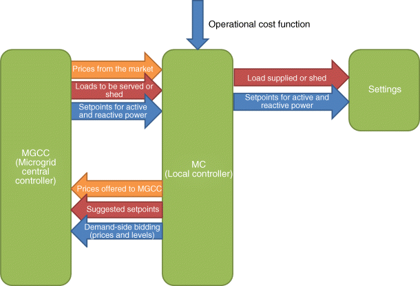
The optimization procedure clearly depends on the market policy adopted in the microgrid operation. In the following section, alternative market policies are considered.
2.7.2 Participation in Energy Markets
2.7.2.1 Market Policies
Two market policies are assumed: In the first policy the MGCC aims to serve the total demand of the microgrid, using its local production, as much as possible when financially beneficial, without exporting power to the upstream distribution grid. Moreover, the MGCC tries to minimize its reactive power requests from the distribution grid. This is equivalent to the “good citizen” behavior, as termed in [18]. For the overall distribution grid operation, such a behavior is beneficial, because:
- at the time of peak demand leading to high energy prices in the open market, the microgrid relieves possible network congestion by supplying partly or fully its energy needs
- the distribution grid does not have to deal with the reactive power support of the microgrid, making voltage control easier.
From the end-users point of view, the MGCC minimizes operational cost of the microgrid, taking into account open market prices, demand and DG bids. The end-users of the microgrid share the benefits of reduced operational costs.
In the second of the two policies, the microgrid participates in the open market, buying and selling active and reactive power to the grid, probably via an aggregator or energy service provider. According to this policy, the MGCC tries to maximize the value of the microgrid, that is, maximize the corresponding revenues of the aggregator, by exchanging power with the grid. The end-users are charged for their active and reactive power consumption at open market prices. From the grid's point of view, this is equivalent to the “ideal citizen” behavior referred to in [18]. The microgrid behaves as a single generator capable of relieving possible network congestion not only in the microgrid itself, but also by transferring energy to nearby feeders of the distribution network.
It should be noted that the MGCC can take into account environmental parameters such as green house gas (GHG) emissions reductions, optimizing the microgrid operation accordingly.
2.7.2.2 Demand Side Bidding
Each consumer may have low and high priority loads allowing him to send separate bids to the MGCC for each type of load. Without loss of generality, it is assumed that each consumer places bids for his demand at two levels, and the prices reflect his priorities. It is preferable that “low” priority loads are not served when the market prices are high, but can either be satisfied at periods of lower prices (shift) or not served at all (curtailment). Two options are considered for the consumers' bids:
In both options, the MGCC
- informs consumers about the external market prices,
- accepts bids from the consumers every hour, corresponding to m minute intervals, and
- sends signals to the MCs, according to the outcome of the optimization routine.
The external market prices help consumers prepare their bids. According to the “good citizen” policy, these prices correspond to the highest prices that the end-users can possibly be charged, if security constraints are not considered. The MGCC optimizes the microgrid operation according to the bids of both DG and loads. In the shift option, the MGCC sums up the DG sources' bids in ascending order, and the demand side bids in descending order, in order to decide which DG sources will operate for the next hour and which loads will be served. This is shown schematically in Figure 2.12. Optimal operation is achieved at the intersection point of the producers and demand bids.
Figure 2.12 The decision made by the MGCC for the shift option. Reproduced by permission of the IEEE
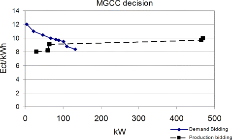
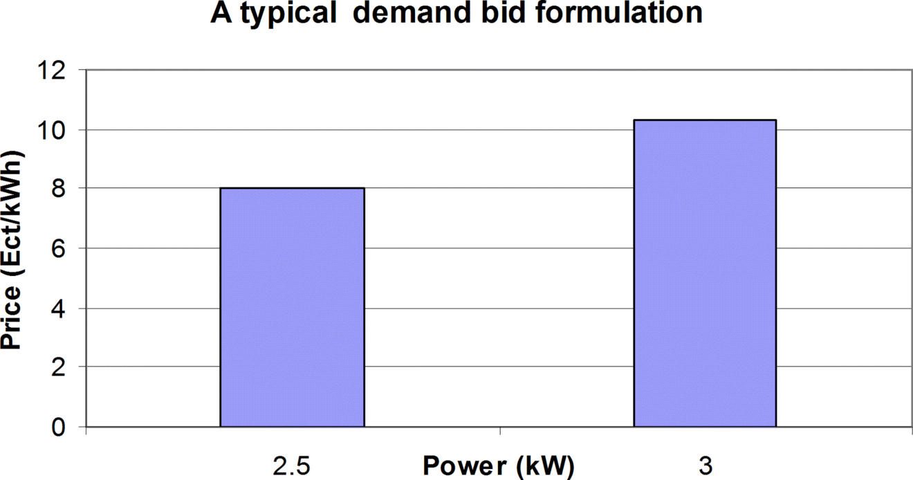
In the curtailment option, consumers bid for the part of their load that they are willing to shed in the next time intervals, if compensated. A possible formulation of the customer bid is shown in Figure 2.13. The main difference with the shift option is that the MGCC knows the current total demand of the microgrid, and sends interruption signals to the MCs, if financially beneficial.
Figure 2.13 Typical bid formulation
2.7.2.3 Security Issues
Similar to large power systems, steady-state security issues concern operation of the microgrid satisfying voltage constraints and power flows within thermal limits. A critical consideration concerns overloading the interconnection between the microgrid with the upstream distribution network. Dynamic security issues could also be considered to ensure microgrid operation under a number of contingencies within and above it. For microgrids the seamless transition between interconnected and islanded mode of operation is of particular importance. Such security considerations can be expressed as additional constraints and might affect the optimization outcome [19].
2.7.3 Mathematical Formulation
2.7.3.1 General
The optimization problem is formulated differently, according to the market policies assumed. Since there are no mature reactive power markets at the distribution level, such a market is not considered within a microgrid. If, however, such a market is to be implemented, the following functions can be easily altered to take it into account.
2.7.3.2 Market Policy 1
As discussed in Section 2.7.2, the MGCC aims to minimize the microgrid operational cost. It is assumed that the operator of the MGCC is a non-profit organization and the end-users share the benefits. The scope is to lower electricity prices for the microgrid end-users and protect them, as much as possible, from the volatility of the open market prices. The objective function to be minimized for each one of the m-minute intervals is
(2.2) ![]()
If demand side bidding is considered, then bid j refers to the bid of the j -th load of the L loads bidding. If the customer is compensated, then the cost of compensation load _bid (bid j), assumed as a linear function of bid j, should be added to the operation cost.
The constraints for this optimization problem are
- technical limits of the DG sources, such as minimum and maximum limits of operation, P–Q curves and start-up times
- active power balance of the microgrid, (Eq. 2.3), where P _demand is the active power demand.
2.7.3.3 Market Policy 2
According to this policy, the MGCC (aggregator) maximizes revenues from the power exchange with the grid. End-users are assumed to be charged with open market prices.
The optimization problem is
![]()
Income comes from selling active power to both the grid and the microgrid end-users. If the demand is higher than the production of the DG sources, power bought from the grid is sold to the end-users of the microgrid. If the demand is lower than the production of the DG sources, term X in (Eqs. 2.4) and (2.5) is zero.
The term Expenses includes costs for active power bought from the grid plus compensation to DG sources. If demand side bidding is considered, relevant costs are added to Expenses.
The MGCC should maximize (Eq. 2.6)
Constraints are the technical limits of the units and that at least the demand of the microgrid should be met, as expressed by (Eq. 2.7).
2.7.4 Solution Methodology
There are several methods for solving the unit commitment (UC) problem, namely to identify which of the bids of both DGs and loads will be accepted. A simple method is the use of a priority list. The DG bids, the load bids, if DSB options are applied, and the external market prices are placed sequentially according to their differential cost at the highest level of production for the specific period. This list is sorted in ascending bid values so that the total demand is met.
DG bids are assumed to have a quadratic form:
Economic dispatch (ED) must be performed next, so that the production settings of the DG sources, whose output can be regulated, and the power exchange with the grid are determined. The production of non-regulated DG and the loads that will not be served has been decided by the UC function, as described in the previous paragraph. If the bids are continuous convex functions, like (Eq. 2.8) then mathematical optimization methods can be utilized, such as sequential quadratic programming (SQP), as described in [20]. Artificial intelligence techniques can also be used, especially if scalar or discontinuous bids are considered [21,22]. The rest of the demand is met by the DG sources and the power bought from the grid.
2.7.5 Study Case
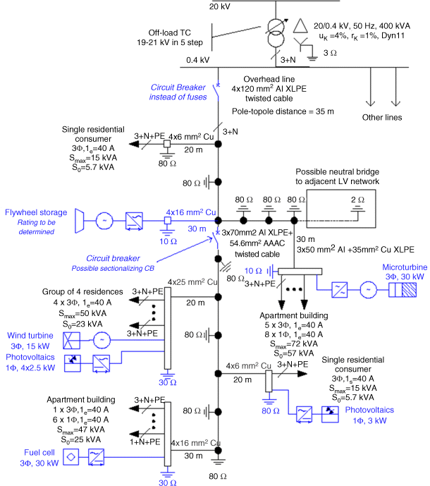
Results from a typical study case LV network, shown in Figure 2.14 [23], are presented in this section. Network data and the other parameters of the study are included for completeness. The network comprises three feeders, one serving a primarily residential area, one industrial feeder serving a small workshop and one commercial feeder. Load curves for each feeder and the whole microgrid for a typical day are shown in Figure 2.15. The total energy demand for this day is 3188 kWh. The power factor of all loads is assumed to be 0.85 lagging. A variety of DG sources, such as a microturbine (MT), a fuel cell (FC), a directly coupled wind turbine (WT) and several PVs, are installed in the residential feeder, as shown in Figure 2.16. It is assumed that all DG produce active power at unity power factor. The resistances and reactances of the lines, the capacity of the DG sources and their bids parameters, installation costs and basic economic assumptions are provided in Appendix 2.A.
Figure 2.14 The study case LV network. Reproduced by permission of the IEEE
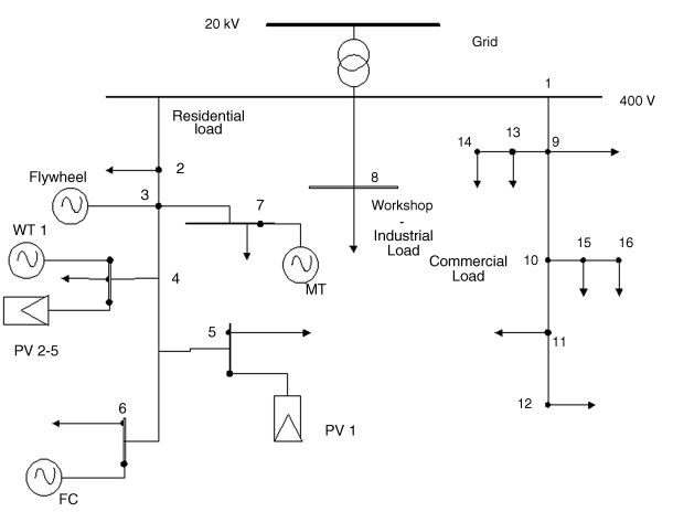
Figure 2.15 Typical load curve for each feeder of the study case network. Reproduced by permission of the IEEE

Figure 2.16 The residential feeder with DG sources
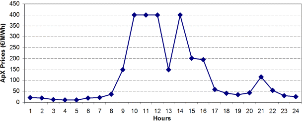
Normalized data of actual wind power and PV production are shown in Figure 2.17. The output of the renewable energy sources (RESs) is not regulated. The respective bids to the MGCC can be the output of a RES forecasting tool, as discussed in Section 2.6 [24]. In addition, actual energy prices from the Amsterdam Power Exchange (APX) in 2003, on a day [25] with volatile prices are used to represent the external market, as shown in Figure 2.18.
Figure 2.17 Normalized RES production
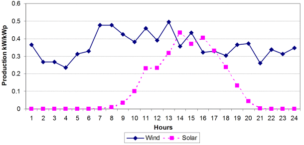
Figure 2.18 Market price variation
2.7.6 Results
For both market policies, the priority list method and the SQP method have been used. The operating cost for the day considered is ![]() 471.83, and the price is 14.8
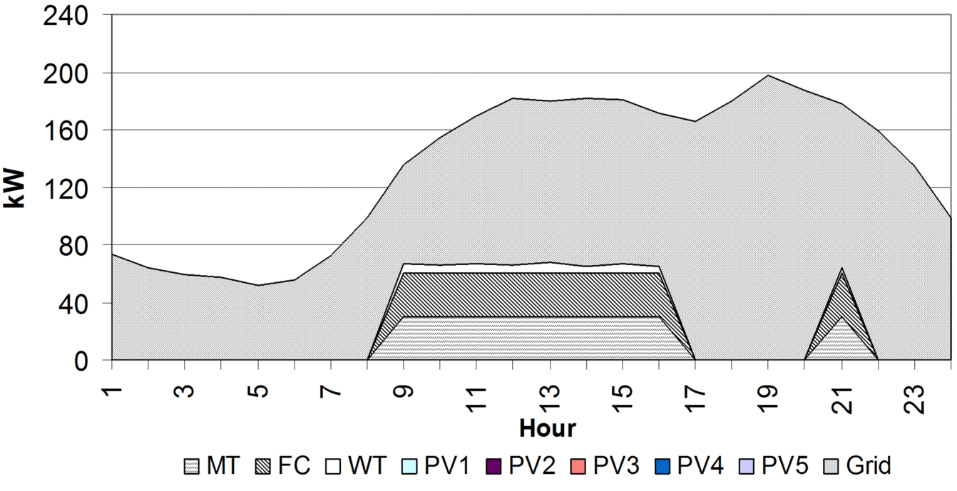
471.83, and the price is 14.8 ![]() ct/kWh, if no DGs are installed. Tables 2.2 and 2.3 provide results for the same day, if the two policies of Section 2.7.3 are simulated. The economic scheduling of the units is shown in Figure 2.19.
ct/kWh, if no DGs are installed. Tables 2.2 and 2.3 provide results for the same day, if the two policies of Section 2.7.3 are simulated. The economic scheduling of the units is shown in Figure 2.19.
Table 2.2 Results of market policy 1. Reproduced by permission of the IEEE
| Cost euro | Difference with actual operation | Average price( |
| 370.09 | 21.56% | 11.61 |
Table 2.3 Results of market policy 2. Reproduced by permission of the IEEE
| Revenues euro | Percentage of revenues | Average price( |
| 101.73 | 21.56% | 14.8 |
Figure 2.19 Typical results of the daily operation. Reproduced by permission of the IEEE
Reduced costs for the consumers by 21.56% are noticed in market policy 1. In market policy 2, the operation of DG does not affect the average price for the consumers of the microgrid; instead the aggregator receives profits of ![]() 102.
102.
The effect of demand side bidding is calculated by assuming that the consumers have two types of loads, “high” and “low” priority, and they bid for their supply, shift option or shedding, curtailment option. It is assumed that all consumers have 2 kW of low priority loads (e.g. an air conditioning) and the price at which they bid is 6.8 ![]() ct/kWh. The rest of their demand is considered as “high” priority load, and the price for the bid is assumed to be 8–10 times higher than the “low” priority price. Results from DSB for the two market policies for the load options described above are presented in the Tables 2.4 and 2.5.
ct/kWh. The rest of their demand is considered as “high” priority load, and the price for the bid is assumed to be 8–10 times higher than the “low” priority price. Results from DSB for the two market policies for the load options described above are presented in the Tables 2.4 and 2.5.
Table 2.4 Results of market policy 1 with demand side bidding. Reproduced by permission of the IEEE
| Shift option – market policy 1 | Curtail option – market policy 1 | |
| Revenues ( |
307.66 | 323.44 |
| Load shed (kWh) | 232 | 232 |
| Cost reduction (%) | 34.79 | 31.44 |
| Average price ( |
10.41 | 10.94 |
Table 2.5 Results of market policy 2 with demand side bidding. Reproduced by permission of the IEEE
| Shift option – market policy 2 | Curtail option – market policy 2 | |
| Revenues ( |
101.73 | 101.73 |
| Load shed (kWh) | 232 | 0 |
| Revenues (%) | 21.56 | 21.56 |
| Average price ( |
14.8 | 14.8 |
The reason why the MGCC following market policy 2, does not shed load in the curtailment option is that the aggregator's revenues are decreased not only from the limitation of DG production, but also from the compensation he has to pay to the loads to be shed. When the load shift option is utilized, the revenues of the aggregator do not change, since the energy produced by the DG sources is sold to the external market at the same prices as in the microgrid internal market. However, the power exchange with the grid is altered by decreasing the grid demand. This service, especially during hours of stress, can be extremely beneficial even for customers that are not part of the microgrid.
This example shows the potential benefits provided by the coordinated operation of DER in a microgrid. Exploiting local DER can significantly reduce costs for the microgrid consumers, or provide revenues to the microgrid's operator, especially in periods of high external market prices. A more complete analysis of microgrid benefits is provided in Chapter 7.
2.8 Decentralized Control
The idea of decentralized control is becoming popular nowadays, not only for microgrids but also for other functions of power systems [26,27]. An interesting approach to designing and developing decentralized systems is based on multi-agent system (MAS) theory. The core idea is that an autonomous control process is assumed by each controllable element, namely inverters, DGs or loads. The MAS theory describes the coordination algorithms, the communication between the agents and the organization of the whole system. Practical applications of these technologies are presented in Sections 6.2.1 and 6.2.2. Next, after a short introduction to MAS theory, these three topics will be addressed.
2.8.1 Multi-Agent System Theory
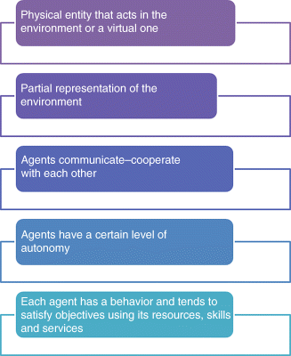
There is no formal definition of an agent, but in the literature [28,29] the following basic characteristics are provided:
- An agent can be a physical entity that acts in the environment or a virtual one, that is, with no physical existence. In our application, a physical entity can be the agent that directly controls a microturbine or a virtual one, such as a piece of software that allows the ESCO or the DSO to participate in the market.
- An agent is capable of acting in the environment, that is, the agent changes its environment by its actions. A diesel generator, by altering its production, affects the production level of the other local units, changes the voltage level of the adjacent buses and, in general, changes the security level of the system, for example, the available spinning reserve.
- Agents communicate with each other, and this could be regarded as part of their capability for acting in the environment. As an example, let's consider a system that includes a wind generator and a battery system: the battery system uses energy from the wind turbine to charge it and it discharges in times of no wind. In order to achieve this operation optimally, the two agents have to exchange messages. This is considered a type of action, because the environment is affected by this communication differently from the case the two agents were acting without any kind of coordination.
- Agents have a certain level of autonomy, which means that they can take decisions without a central controller or commander. To achieve this, they are driven by a set of tendencies. For a battery system, a tendency could be: “charge the batteries when the price for the kWh is low and the state of charge is low, too.” Thus, the MAS decides when to start charging, based on its own rules and goals and not by an external command. In addition, the autonomy of every agent is related to the resources that it possesses and uses. These resources could be the available fuel for a diesel generator.
- Another significant characteristic of the agents is that they have partial representation – or no representation at all – of the environment. For example, in a power system the agent of a generator knows only the voltage level of its own bus and it can, perhaps, estimate what is happening in certain buses. However, the agent does not know the status of the whole system. This is the core of the MAS technology, since the goal is to control a very complicated system with minimum data exchange and minimum computational resources.
- Finally, an agent has a certain behavior and tends to satisfy certain objectives using its resources, skills and services. An example of these skills is the ability to produce or store power and an example of the services is the ability to sell power in a market. The way that the agent uses its resources, skills and services characterizes its behavior. As a consequence, it is obvious that the behavior of every agent is formed by its goals. An agent that controls a battery system, and whose goal is to supply uninterruptible power to a load, will have different behavior from a similar battery whose primary goal is to maximize profits by bidding in the energy market.
The agents' characteristics are summarized in Figure 2.20.
Figure 2.20 Agents characteristics
2.8.1.1 Reactive versus Intelligent Agents
Any entity or device that has one or more of the characteristics of Figure 2.20 can be considered an agent. But how smart can an agent be?
Let's consider an under-voltage relay. The relay has the following characteristics:
- has partial representation of the environment (measures the voltage locally only),
- possesses skills (controls a switch), and
- reacts autonomously, according to its goals (opens the switch when the voltage goes beyond certain limits).
According to the literature [28], this type of entity can be considered as a reactive agent that just responds to stimuli from the environment.
What is a cognitive or intelligent agent? Again, there is no formal definition of what an intelligent agent is, but some basic characteristics can be listed:
- memory to acquire and store knowledge of the environment: The memory is one fundamental element of the intelligence and the ability to learn.
- ability to perceive the environment: Having an internal modeling and representation of the environment, detailed enough, is mandatory in order to support the decision making process. The environment model allows the agent to understand the environment state having local information and to predict the effect of a possible action on the environment.
- ability to take decisions according to its memory and the status of the environment and not just to react: The agent has a process (algorithm) that uses the model of the environment and the measurements in order to define the next actions.
- ability for high level communication: The agents have the ability to exchange knowledge and use communication as a tool to proceed with complex coordinated actions.
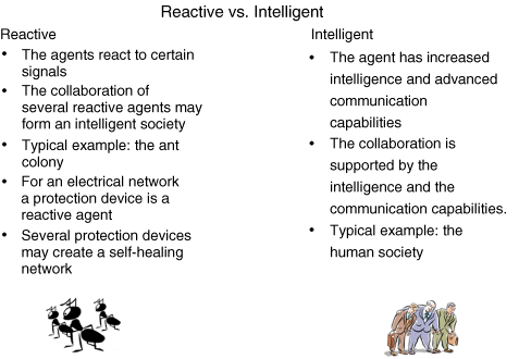
Figure 2.21 summarizes the differences between reactive and intelligent agents, using two well-known societies, human society and an ant colony. In the case of ant colonies, ants do not have significant intelligence and they simply react to stimuli; however, they manage to achieve their main goal, to preserve the society and feed the queen. Human society is formed of intelligent agents: humans. The human intelligence is strengthened by the capability to exchange ideas and knowledge, that is, to communicate.
Figure 2.21 Reactive and intelligent agents
Finally, we should define the concept of the multi-agent system. An MAS is a system comprising two or more reactive or intelligent agents. It is important to recognize that usually there is no global coordination, simply the local goals of each individual agent are sufficient for a system to solve a problem. Furthermore, under Wooldridge's definitions [30], intelligent agents must have social ability and therefore must be capable of communication with each other.
2.8.2 Agent Communication and Development
Communication is one of the most critical elements that allow the intelligent agents to form a society, a multi-agent system. The transmission of the messages can be done via any traditional communication system, such as IP communications, wired or wireless channels. This section focuses on the context and the structure of the messages. Figure 2.22 presents the agent version of the story of the Tower of Babel, where the workers could not finish the tower due to the lack of communication [31].
Figure 2.22 The problem of communication. Reproduced by permission of the IEEE
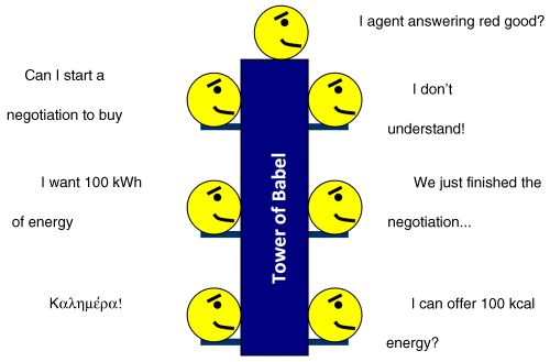
This figure presents the main characteristics of the agent communication language (ACL) and the associate problems:
All these issues are further analyzed in the following sections. Before that, the Foundation of Intelligent Physical Agent and a platform for agent development are introduced.
2.8.2.1 Java Agent Development Framework (JADE)
JADE (Java Agent DEvelopment framework [32]) is a software development framework aimed at developing multi-agent systems and applications conforming to the Foundation of Intelligent Physical Agent's [33] (FIPA's) standards for intelligent agents. FIPA is an IEEE Computer Society standards organization that promotes agent-based technology and the interoperability of its standards with other technologies. FIPA developed a collection of standards that are intended to promote the interoperation of heterogeneous agents and the services that they can represent. The complete set of specifications covers different categories: agent communication, agent management, abstract architecture and applications. Of these categories, agent communication is the core category at the heart of the FIPA multi-agent system model.
JADE includes two main products: a FIPA-compliant agent platform and a package to develop Java agents. JADE has been fully coded in Java, and so an agent programmer, in order to exploit the framework, should code agents in Java, following the implementation guidelines described in the programmer's guide. This guide supposes that the reader is familiar with the FIPA standards, at least with the Agent Management specifications (FIPA no. 23), the Agent Communication Language and the ACL Message Structure (FIPA no. 61) (Table 2.6).
Table 2.6 Structure of an ACL Message
| Parameter | Description |
| performative | Type of the communicative act of the message |
| sender | Identity of the sender of the message |
| receiver | Identity of the intended recipients of the message |
| reply-to | Which agent to direct subsequent messages to within a conversation thread |
| content | Content of the message |
| language | Language in which the content parameter is expressed |
| encoding | Specific encoding of the message content |
| ontology | Reference to an ontology to give meaning to symbols in the message content |
| protocol | Interaction protocol used to structure a conversation |
| conversation-id | Unique identity of a conversation thread |
| reply-with | An expression to be used by a responding agent to identify the message |
| in-reply-to | Reference to an earlier action to which the message is a reply |
| reply-by | A time/date indicating when a reply should be received |
JADE is written in the Java language and is made of various Java packages, giving application programmers both ready-made pieces of functionality and abstract interfaces for custom application-dependent tasks. Java was the programming language of choice because of its many attractive features, particularly geared towards object-oriented programming in distributed heterogeneous environments; some of these features are object serialization, reflection API and remote method invocation (RMI).
The standard model of an agent platform, as defined by FIPA, is presented in Figure 2.23.
Figure 2.23 The AMS platform
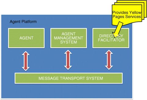
The agent management system (AMS) is the agent that exerts supervisory control over access to and use of the agent platform. Only one AMS will exist in a single platform. The AMS provides white-page and life-cycle service, maintaining a directory of agent identifiers (AIDs) and the agent state. Each agent must register with an AMS in order to get a valid AID.
The directory facilitator (DF) is the agent that provides the default yellow page service in the platform. The message transport system, also called agent communication channel (ACC), is the software component controlling all the exchange of messages within the platform, including messages to/from remote platforms.
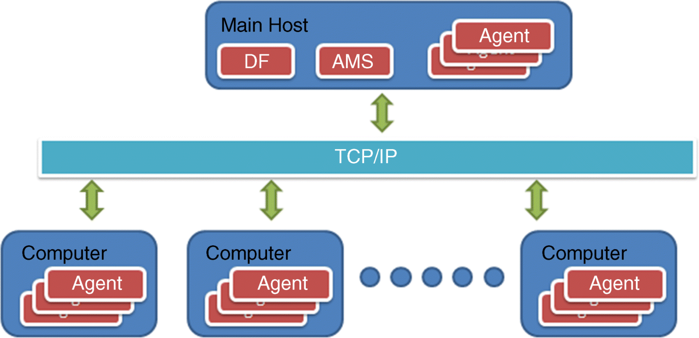
JADE fully complies with this reference architecture, and when a JADE platform is launched, the AMS and DF are immediately created, and the ACC module is set to allow message communication. The agent platform can be split on several hosts. Only one Java application, and therefore only one Java virtual machine (JVM), is executed on each host. Each JVM is a basic container of agents that provides a complete run-time environment for agent execution and allows several agents to concurrently execute on the same host. The main container, or front-end, is the agent container where the AMS and DF reside, and where the RMI registry, that is used internally by JADE, is created. The other agent containers instead, connect to the main container and provide a complete run-time environment for the execution of any set of JADE agents. The installation of the system requires at least one computer that hosts the JADE platform. The agents may exist in this computer or other computers in communication via the internet/Ethernet (Figure 2.24).
Figure 2.24 The implementation of the MAS
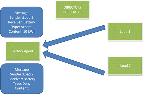
A critical component of this architecture is the DF, which is actually the basis for the development of plug-and-play capabilities. To further understand this, a simple example comprising a battery and two loads is considered. The procedure runs as follows: all agents, by the time they are created, automatically announce to the DF the services that they could provide to the system (Figure 2.25). In this example, the load agents participate in the system as buyers of energy, while the battery agent sells energy. The battery agent starts the transaction by sending a request to the DF. The DF agent provides the list of agents that can buy energy (Figure 2.26). Next, the battery agent sends a request to all the members of the list (Figure 2.27). Finally, the load agents respond, as shown in Figure 2.28, that is, one load agent refuses the offer, while the other agent accepts it and announces the amount of energy it needs.
Figure 2.25 The agents declare their services to the DF agent
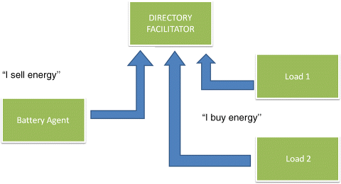
Figure 2.26 The battery agent asks for the list of agents that provide a “buying” service
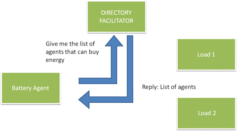
Figure 2.27 The battery agent sends message to the load agents proposing to “sell” energy
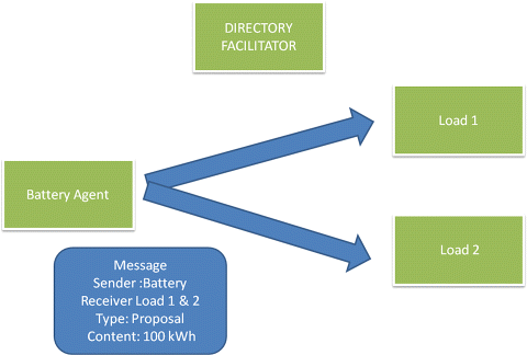
Figure 2.28 The load agents respond to the battery agent
2.8.3 Agent Communication Language
The content of each message between the agents is based on the formal agent communication language (ACL) which, among others, has two main characteristics:
A high-level language is necessary in order to support the fundamental operations of the intelligent agent, which are the collaboration and the intelligence. Next, the basic structure of an ACL message is provided.
This structure addresses the technical problems presented in the example of the Tower of Babel of Figure 2.22. First of all, it has a structure allowing a proper parser to easily identify who is the sender or what is the content of the message. Next, the sender, by defining the ontology it uses, allows the receiver to understand the language of the message. Finally, the attributes “reply-to” and “Conversation ID” enable the formulation of parallel and complex dialogues.
2.8.4 Agent Ontology and Data Modeling
In computer science, an ontology represents knowledge, as a set of concepts and relationships between pairs of concepts. The concepts should belong to the same domain, namely in the electricity grid the term energy refers to kWh, not calories. Agents use the ontology for passing of information, formulating questions and requesting the execution of actions related to their specific domain.
The power engineering community has devoted significant effort to defining data standards for various application areas. One example is the common information model IEC 61970 (CIM [34]) for data exchange between energy management systems and related applications. The common information model (CIM) is a unified modeling language (UML [35]) model that represents all the major objects in an electric utility enterprise typically involved in utility operations. CIM provides a set of object classes and attributes, along with their relationships. In this way, energy management system (EMS) applications developed by different vendors can exchange information. This standard cannot be directly used for the formulation of an ontology, as the agent communication language requires more complex structures than a data model. However, there is potential to use it as a basis for the development of an ontology.
2.8.5 Coordination Algorithms for Microgrid Control
In this section, coordination algorithms for decentralized control of microgrids are presented. The main issues in all algorithms are convergence to the optimal solution and scalability (complexity). Typically, an algorithm that guarantees convergence to the optimal solution cannot handle a very large number of nodes in a reasonable time.
2.8.5.1 Auction Algorithms
The auction algorithm is a type of combinatorial optimization algorithm that solves assignment problems and network optimization problems with linear and convex/nonlinear cost. The main principle is that the auctioneers submit bids to obtain goods or services. At the end of an iterative process, the highest bidder is the winner. For microgrids, goods can be an amount of energy.
English auction
A popular and very simple type of auction is the English auction. The procedure starts with the auctioneer proposing a price below that of the actual market value and then gradually raising the price. The actual value is not announced to the buyers. At each iteration, the new, higher price is announced and the auctioneer waits to see if any buyers are willing to pay the proposed price. As soon as one buyer accepts the price, the auctioneer proceeds to a new iteration with an increased price. The auction continues until no buyers accept the new price. If the last accepted price exceeds the actual market value, the good is sold to that buyer for the agreed price. If the last accepted price is less than the actual value, the good is not sold.
Dutch auction
A similar approach is the Dutch auction. In this case, the procedure starts with the auctioneer asking a price higher than the actual value, which is decreased until a buyer is willing to accept it, or a minimum value (actual value) is reached. The winning participant pays the last announced price.
Theoretically, both approaches are equivalent and lead to the same solution. Many variations on these auction systems exist, for example, in some variations the bidding or signaling from the buyers is kept secret.
Symmetric Assignment
A more advanced auction algorithm is proposed by [36,37] to solve the symmetric assignment problem, which is formulated as follows:
Consider n persons and n objects that should be matched. There is a benefit a ij for matching person i with object j. In the presented application, the benefit for each person is his revenues for obtaining object j, that is, an agreement for producing a certain amount of energy. The main target is to assign the persons to objects and to maximize the total benefit, expressed as:
(2.9) ![]()
The price p is an algorithmic variable that is formed by the bids of all persons and expresses the global desire. The prices of all objects form the price vector. These prices should not be confused with the market prices. Also, the difference between the benefit and the price is the actual value of an object for a specific person. The actual value for a specific object is different for two persons, since it is related to the benefit. At the beginning of the iterations, the price vector is zero and so the actual value is equal to the benefit, although variations of the proposed methods use initial non-zero values for faster convergence.
The auction algorithm calculates the price vector p, in order to satisfy the ![]() -complementary slackness condition suggested in [36,37]. The steps are as follows:
-complementary slackness condition suggested in [36,37]. The steps are as follows:
At the beginning of each iteration, the ![]() -complementary slackness condition is checked for all pairs (i,ji) of the assignment. The ji is the object j that person i wants to be assigned to. So the formulation of this condition is
-complementary slackness condition is checked for all pairs (i,ji) of the assignment. The ji is the object j that person i wants to be assigned to. So the formulation of this condition is
(2.10) ![]()
A (i) is the set of objects that can be matched with person i. This inequality has two parts: α ij − p j is the actual value of object j for person i, as described before. The right part refers to the object that gives maximum value to person i minus ![]() , where
, where ![]() is a positive scalar, added in the bid of each object, in order to avoid possible infinite iterations in case two or more objects provide maximum benefit to the same person, as explained later.
is a positive scalar, added in the bid of each object, in order to avoid possible infinite iterations in case two or more objects provide maximum benefit to the same person, as explained later.
If all persons are assigned to objects, the algorithm terminates. Otherwise, a non-empty subset I of persons i that are unassigned is formed. Similarly, the non-empty subset P (j) is formed by the available objects. The following two steps are performed only for persons that belong to I.
The first step is the bidding phase, where each person finds an object j which provides maximal value and this is
(2.11) ![]()
Following this, the person computes a bidding increment
(2.12) ![]()
u i is the best object value
(2.13) ![]()
and w i the second best object value
(2.14) ![]()
According to these equations, the bidding increment is based on the two best objects for every person. If there are two or more bids for an object, its price rises, and the price increment is the larger bidding increment between the bids. It is obvious that, if the scalar ![]() = 0 and the benefits for the first and the second best object are the same, then γ i = 0 and this leads the algorithm to infinite iterations. The
= 0 and the benefits for the first and the second best object are the same, then γ i = 0 and this leads the algorithm to infinite iterations. The ![]() scalar ensures that the minimum increment for the bids is γ i =
scalar ensures that the minimum increment for the bids is γ i = ![]() .
.
The next phase is the assignment phase, where each object j selected as best object by the non-empty subset P (j) of persons in I, determines the highest bidder
(2.15) ![]()
Object j raises its prices by the highest bidding increment ![]() , and gets assigned to the highest bidder i j. The person that was assigned to j at the beginning of the iteration, if any, becomes unassigned.
, and gets assigned to the highest bidder i j. The person that was assigned to j at the beginning of the iteration, if any, becomes unassigned.
The algorithm iterates until all persons have an object assigned. It is proven that the algorithm converges to the optimal solution, as long as there is one. The maximum number of iterations is
(2.16) ![]()
and the algorithm terminates in a finite number of iterations if
(2.17) ![]()
Application of Auction Algorithms
In order to describe how auction algorithms are applied in a MAS environment, the following simplified example is presented [38]. Two types of physical agents and one type of virtual agent are introduced. The two physical agents are the production unit agent and the load unit agent. These two agents are physical, because they directly control a production or storage unit and a load panel, respectively. The third type is the market agent. This agent is virtual because it cannot control the market in any way and just announces the prices for selling or buying energy. All other agents introduced later in this section are virtual, and their operation concerns the auction algorithm only.
Let us consider that there are x production units with a total capacity of X and y loads with a total capacity of Y. The symmetrical assignment problem requires that X = Y. In order to overcome the problem of surplus or deficient local production, a virtual load with a proper price is added, as shown in Figure 2.29. Similarly, virtual production can be added. The virtual load or production corresponds to the extra energy that is bought from or sold to the grid. As mentioned before, it is assumed that the grid can offer or receive infinite amounts of energy.
Figure 2.29 The blocks of energy that form the assignment problem. Reproduced by permission of the IEEE
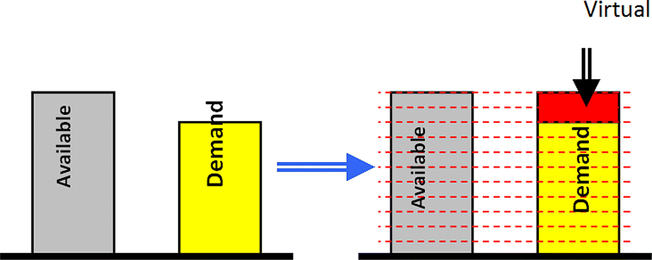
In order to apply the algorithm for the solution of the symmetric assignment problem, the load should be divided into equal blocks, similar to the available production. Blocks that belong to the same load have equal benefits, since the system will provide all the necessary power for the whole load or none. For example, if we consider a water heater that demands 500 Wh within the next 15 minutes, the system should provide the full 500 Wh or nothing.
Mapping the fundamental assignment problem to the microgrid management, the “persons” correspond to the blocks of available power and the “objects” to the demand blocks. The agent market operation based on the described model is illustrated in Figure 2.30. The production unit agents control the DER, the load unit agents represent the loads and the grid agent generates market player agents. The market player agents are virtual agents and their task is to accomplish the negotiation. There are two types of market player agents: the seller and the buyer. The buyer is the object in the assignment problem, and the seller is the person. Every market player agent represents a single block of energy.
Figure 2.30 The virtual market player agents that are created for the need of the negotiation. Reproduced by permission of the IEEE

Similar to the local loads, the virtual load is represented by market player agents that are created from the grid agent. According to the proposed market model, each producer has the ability to sell all its production to the grid and, similarly, every load can buy energy from the grid. For this reason, the grid agent finds the number of pairs of market player agents (sellers and buyers) and creates extra sellers and buyers. The number of the agents is equal to market agents that are created from the production unit agents and the load unit agents. In this way, buying or selling energy from the grid is determined by the algorithm.
A major issue in microgrid operation is the estimation of the upper limits for the demand or the available power of each DER for the next time interval. This should be done separately for each participant. It should be noted that although forecasting techniques are well advanced for larger interconnected systems and typically hourly resolution times, there is little experience in forecasting with a high temporal resolution (e.g. <15 minutes) with a horizon of 3–4 hours for very small loads, like the loads in a microgrid, as already discussed in Section 2.6.
In this application the upper limit is defined by two methods, depending on the type of load or DER. The first method is to consider that the upper limit is the nominal capacity. For units such as a diesel generator or a water heater this is quite realistic. By contrast, for units like photovoltaic panels, wind generators or lighting loads, the persistence method is used, i.e. it is assumed that the average energy production or demand for the next 15 minutes will be the same as the current one.
It should be noted that other functionalities of the microgrid (such as security check, battery management and voltage control) can be included in this operation. For example, the offered power of battery bank production could be reduced in order to maintain the state of charge and keep certain amount of energy to serve the system, in case of a grid emergency.
2.8.5.2 Multi-agent Reinforcement Learning
Alternative approaches can be based on heuristic algorithms, such as multi-agent reinforcement learning (RL) [22]. Reinforcement learning is a family of iterative algorithms that allows the agent to learn a behavior through trial and error.
One well-known algorithm is Q-learning [39]. Its main characteristic, in the multi-agent environment is that each agent runs its own Q-learning for the part of the environment it perceives, but its target is to optimize the overall microgrid performance or a specific common goal.
Q-learning is a reinforcement learning algorithm that does not need a model of its environment and can be used online. The Q-learning algorithm operates by estimating the values of state-action pairs. The value Q (s,a) is defined as the expected discounted sum of future payoffs obtained by taking action α from state s and following an optimal policy thereafter. Once these values have been learned, the optimal action from any state is the one with the highest Q-value. After being initialized, Q-values are estimated on the basis of experience, as follows:
- From the current state s, select an action a. This will bring an immediate payoff r, and will lead to a next state s ′.
- Update Q (s,a) based upon this experience as follows:
 ) where k is the learning rate, 0 < γ < 1 is the discount factor.
Alternative learning algorithms can be used, including the Nash-Q learning, which is a general sum MAS reinforcement algorithm for a stochastic environment. The main problem is that the execution times are prohibitive because the Nash-Q learning requires that the Q table includes as a parameter the actions of the other agents. For systems like microgrids, the Q table becomes huge, requesting a large number of episodes for training. Other approaches propose forecasting the decisions of other agents, but this also cannot be easily done in microgrid applications.
The main problem in the application of reinforcement learning is the modeling of the environments which affects the size of the Q table and as a consequence the convergence speed. All actions and system states are included in the Q table as
(2.18) ![]()
a1, a2…an is the selected action of agent 1, agent 2… agent n.
Another concern is that the environment is stochastic, since we still cannot predict accurately the effect on the system state after switching a load or sending a command to change the setpoint of a DG. An approach proposed in [40,41] is to replace all actions with one single variable called transition, which represents the final result to the environment of all actions of all the agents.
![]()
(2.19) ![]()
The agent selects the action that will lead the system to the best state (transition) considering that the other agents will follow the same policy. The selection of actions is based on the following equation:
This means that, for each transition, each agent selects the action that maximizes the Q value and they all add these values at each transition. The selected transition is the one with the highest value.
Let's consider an example of the application of the RL algorithm to microgrid black start. After the black out, a simple procedure is followed:
It should be noted that the algorithm considers the steady state of the system and does not handle transient phenomena. The algorithm focuses on how to ensure power supply to the critical loads for a predefined period, for example 24 hours ahead. In this case, the agents have to learn to use the available resources in the most efficient way.
Each agent executes a Q-learning procedure for the part of the environment that it perceives. For the formulation of the problem, the variables that will be inserted in the Q table should be defined first. It should be noted again that it is important to keep the size of the Q table small in order to reduce the number of calculations.
The environment state variable forms a table of 24 elements, one for every hour of the schedule. The production units are characterized by one more variable, the available fuel, with three values: {low, medium, high}. For battery units this variable reflects the state of charge. Finally, for the loads, there is a variable called remain with values {low, medium, high}, indicating how many hours they need to be served.
The transition variable is considered next, with three values: {up, neutral, down}. This variable is an indication of the behavior of the other agents and the state of the system, as explained before. The purpose of this variable is to identify the most likely next states of the system. For example, if the transition has value {down}, the system will go to a worse state, no matter what the action of the individual agent might be. The definition of a worse or better state depends on the type of problem. For example, in the interconnected system operation a worse case is when the system receives energy from the upstream networks. In non-interconnected mode, the worse state is when the system consumes stored energy.
Accordingly, the size of the Q table for each agent is:
- storage units: Q (horizon{24}, fuel{3}, environment {3}, transition {3},action {3}) = 1944 elements
- generation units: Q (horizon{24}, fuel{3}, environment {3}, transition {3},action {2}) = 1296 elements
- loads: Q (horizon{24}, environment {3}, remain{3}, transition {3}, action {2}) = 1296 elements.
The agent learns the value of its action in the various states of the system. For this case study, the agents are able to act as in Table 2.7.
Table 2.7 Actions of the agents. Reproduced by permission of the IEEE
| Type | Actions | |
| 1 | load | on off |
| 2 | storage unit | produce stop store |
| 3 | production unit | stop produce |
The intermediate reward for the algorithm is calculated from:
(2.21) ![]()
N is a normalization parameter obtained by dividing the maximum production capacity of the unit by the total production capacity of the system. This ensures a weighted participation of all units, for example, a 100 kW unit affects more the final actions than a 1 kW unit.
- The transition reward has a value of 1/24 when the system stores energy, 0 if it remains at the same level and −1/24 when the system consumes stored energy.
- The final state reward is received in the final step and has value 1 if the system has sufficient energy for the whole period (24 h), and −1 if not.
- The K parameter is different for loads and production/storage units. For production/storage units it indicates the remaining fuel, and for load the time (in percentage that the load should be served).
This algorithm needs to be executed if there is a significant change in the system, such as the installation of a new unit. This is presented in Figure 2.31. After the execution, every agent has learnt what to do in case of an emergency. Consider for example, that the system is in zero power exchange with the slack. The agents have to select one of three transitions {up, neutral, down}. In order to decide which transition to follow, they announce to each other the Q values for each transition in the current state. The selected transition is given by (Eq. 2.20).
Figure 2.31 Time schedule of the algorithm. Reproduced by permission of the IEEE
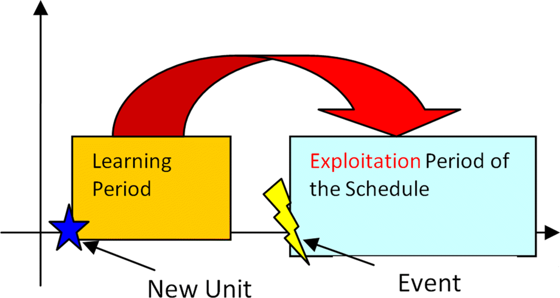
Selecting for example an “up” transition means that some agents have surplus power and they offer it to the system having in mind that the selected path will lead to a good final solution. The good solution is the one that ensures energy adequacy for the whole 24 hour period.
As an example, consider a microgrid system comprising:
- diesel generator,
- battery bank,
- load,
- renewable energy sources.
The simulation has two parts. The first part is training (exploration), in order to find the Q values. The second part is exploitation of the algorithm in isolated operation. Several simulations of the operation of the system were performed in order to validate whether the agents find the solution that ensures energy adequacy. Furthermore, simple software was developed, allowing each agent to decide absolutely independently of each other, in order to compare the solution with the one of the reinforcement learning algorithms.
The critical loads and the renewable energy sources participate in the simulation of the exploitation, but there is no need to train the respective agents, since they do not control their actions.
A learning rate k = 0. 95 and discount factor γ = 0.1 are assumed. The algorithm converges after 20 000 iterations, which means that there are no significant changes in the values of the Q table in more iterations. In order to ensure that this is the final solution, multiple runs have been made with the same schedule, but with different initializations of the Q table, as well as multiple runs with the same initial Q table. Since there is no interaction between the agents during the learning period, every agent needs around 40 seconds in a single PC with 3 GHz processor to complete the training.
In Figure 2.32, an instant of the results of the algorithm for the battery is shown. The vertical axis presents the Q value and the horizontal axis the time step. The agent chooses the action with the higher Q value. The battery agent appears to learn how to handle the islanded operation. The agent starts exhibiting a conservative behavior at the beginning, since it does not know what will happen next, so the system tries to save energy for the next hours. This is shown by the fact that the battery Q values are higher for zero production in the first 8 hours, in comparison to the Q values for production or storing. By the time the energy adequacy is guaranteed, the agents start to serve extra loads, like the battery, in the hours between 10 and 15. It should be noted that this is a simplified example. In a more complex application, the Q values for the battery should be compared with the corresponding Q values of the other agents.
Figure 2.32 Results for restoration study case
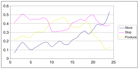
2.8.6 Game Theory and Market Based Algorithms
Another interesting approach is to use game theory and market based rules. The various agents know their own benefit and cost, and they respond to price signals. This approach is using the principles of game theory, and if the rules of the game are correct, the system will balance at the optimal point.
Game theory is a branch [42,43] of applied mathematics that studies the interaction of multiple players in competitive situations. Its goal is the determination of the equilibrium state at which the optimal gain for each individual is achieved. More specifically, the theory of non-cooperative games studies the behavior of agents in any situation where each agent's optimal choice may depend on its forecast of the choices of its opponents [43]. Various categories of games exist, depending on the assumptions regarding the timing of the game, the knowledge associated with the payoff functions and last but not least the knowledge regarding the sequence of the previously made choices. More specifically, the games can be categorized as:
- static/dynamic games: the players choose actions either simultaneously or consecutively.
- complete/incomplete information: each player's payoff function is common knowledge among all the players or at least one player is uncertain about another player's payoff function.
- perfect/imperfect information (defined only for dynamic games): at each move in the game the player with the move knows or does not know the full history of the game thus far [42].
A simple but realistic example is to assume a dynamic game of complete and perfect information: the consumers and the DG units are not considered as competitive entities, but their payoff functions are publicly available, while the history of the game at each stage is known. The timing of such a game is as follows:
The solution of such a game is determined as the backwards-induction outcome. At the second stage of the game, player 2 will solve the following problem, given the action a 1 previously chosen by player 1:
(2.22) ![]()
It is assumed that for each a 1 in A 1, player 2's optimization problem has a unique solution, denoted by R 2(a 1) [42]. This is player 2's best response to player 1's action. Since player 1 can solve player 2's problem as well as player 2 can, player 1 should anticipate player 2's reaction to each action a 1 that player 1 might take, so player 1's problem at the first stage amounts to
(2.23) ![]()
It is assumed that this optimization problem for player 1 also has a unique solution, denoted by ![]() . So
. So ![]() is the backwards induction outcome of the game.
is the backwards induction outcome of the game.
A detailed description of game theory concepts can be found in [42,43].
2.8.7 Scalability and Advanced Architecture
A key question about the applicability of decentralized approaches and especially of MAS systems, concerns their suitability for control of larger systems with several hundreds of nodes, as real microgrids can be. This problem is referred to as the scalability problem, and it is very important for the development of any control system. It should be noted that service oriented architectures and cloud computing provide technical tools to address this issue, but these are beyond the scope of this book and we will focus in the main concept in this section.
This concept can be better explained by considering the organization of human societies and cities. Many people living in an area form a village or a city. Next, many cities and villages form a county and many counties form a country. This concept is shown in Figure 2.33. Accordingly, DG units and controllable loads form small microgrids and accordingly small MASs. These MASs form larger MASs and so on. The grouping may be realized based on electrical and topological characteristics such as having a common MV transformer.
The groups of MASs are organized in three levels. The three levels are presented in Figure 2.34. All the agents associated directly with the control of the production units or controllable loads belong to the field level. These agents directly communicate and control a production unit or a load and may be organized in a MAS according to the physical constraints of the system. Each of these MASs also has an agent that is responsible for communicating with other higher-level MASs, in order to cooperate with them. These MASs belong to the management level. Finally, these MASs may form larger MASs in order to participate at the enterprise level.
Figure 2.34 Management of the agents
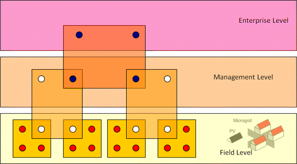
From a microgrid point of view, the field level of Figure 2.34 is associated with each individual microgrid control, the management level is associated with multi-microgrids and individual DGs at MV, as further discussed in Chapter 5, while the enterprise level is related to a higher level aggregation, such as coordinated market participation.
Figure 2.35 Type of fuzzy information considered for the microgrid load and generation
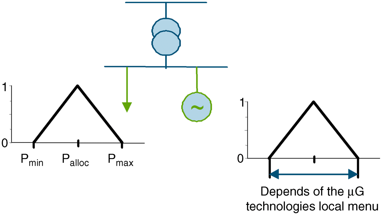
2.9 State Estimation
2.9.1 Introduction
State estimation (SE) is very important for the management of active distribution networks. It can be applied to a wider area of the distribution network including one or more microgrids and DGs connected at the MV level, and provides to the DSO an overview of the system operating conditions. In this way, it allows the DSO to define appropriate control strategies to be adopted, whenever necessary.
Distribution state estimation (DSE) techniques [44–49] are different from SE in transmission systems [50,51]. The former have been developed to make up for the lack of measured data at MV and LV levels, while the latter reduce the uncertainty of the available redundant measurements. In distribution grids, real-time measurements are available only at the primary substations (voltage magnitudes, power flows and circuit breaker statuses) and feeders (current magnitudes), and so, full network observability is impossible. In order to ensure network observability, pseudo-measurements (forecasted or near real-time load injections), that are stochastic in nature, need to be used at all unmeasured nodes [45,52,53]. This data can be gathered by automated meter reading devices [54] and can be stored in accessible databases. Virtual measurements with no error (zero injections at network nodes that have neither load nor generation, zero voltage drops at closed switching devices and zero power flows at open switching devices) can be also utilized. The DSE will process this real-time and forecasted data to produce the state vector consisting of nodal voltages (magnitudes and phase angles) and transformer tap positions.
Feeders are mainly three-phase radial, but have laterals that can be single- or two-phase. Furthermore, loads on the feeders are distributed and can be single- and two-phase (for residential service) or three-phase (for commercial and industrial service). Therefore, distribution systems are unbalanced by nature. Nevertheless, to avoid modeling complexities, the network is assumed to be balanced, and the single phase equivalent network model is considered for state estimation analysis.
The commonly used weighted least-squares (WLS) estimation method [51] can be adopted for distribution state estimation, considering the following nonlinear measurement model:
(2.24) ![]()
The nodal states can be estimated by minimizing the quadratic objective function:
(2.25) ![]()
where ![]() is the measurement vector,
is the measurement vector, ![]() is the vector of nonlinear functions relating measurements to states,
is the vector of nonlinear functions relating measurements to states, ![]() is the true state vector,
is the true state vector, ![]() is the vector of normally distributed measurement errors, with
is the vector of normally distributed measurement errors, with ![]() and
and ![]() , and
, and ![]() is the variance of the i th measurement error. Real-time measurements will have lower variance than pseudo-measurements. The state estimate
is the variance of the i th measurement error. Real-time measurements will have lower variance than pseudo-measurements. The state estimate ![]() can be obtained by iteratively solving the following equations:
can be obtained by iteratively solving the following equations:
(2.26) ![]()
where, ![]() is the iteration index,
is the iteration index, ![]() ,
, ![]() ,
, ![]() is the Jacobian matrix and
is the Jacobian matrix and ![]() is the gain matrix.
is the gain matrix.
The presence of a large number of load injection pseudo-measurements may give rise to convergence problems [55]. In order to overcome this problem, robust SE algorithms need to be applied [50]. One such algorithm, based on orthogonal transformations, is presented in Section 2.9.2.
With the increasing number of nodes involved in distribution networks, the DSE may not be suitable for operating as a centralized algorithm. The feeders can be divided into zones or areas, and local state estimations can be executed independently, sending their results to the DMS, where a coordinated state estimator will calculate the system-wide state [56,57]. When partial lack of communication occurs in some areas, the local SE processes can continue with the remaining areas.
2.9.2 Microgrid State Estimation
The structure of a typical LV distribution network, including a microgrid system, connected to the main MV grid, has been shown in Figure 2.4. A microgrid state estimator (MSE) will follow the concepts of distribution state estimators, receiving a limited number of real-time measurements from the network [47,58]. Near-real-time measurements of voltage and active and reactive injections at DG sites can be also available at predefined time intervals. Since this data is inadequate for state estimation, forecasted node injections obtained from historical or near-real-time load data should be used. However, the number of loads connected to the distribution network may be large, so it will be impractical to telemeter all those points.
Measurement time skew is a consideration when combining large area data received via a data communication network. Due to limited communication infrastructure, near real-time data from DG sources or loads may be sent to the DMS through different communication channels causing additional time skew problems. In order to accommodate the effects of randomly varying arrival of measurement data, a stochastic extended Kalman filter (EKF) algorithm can be used to improve time skewed measurement data [59].
An important issue in state estimation modeling is the identification of network configuration (topology). In transmission state estimation the statuses of switching devices are processed by the network topology processor (NTP) to define the bus/branch network model, by merging bus sections joined by closed switching devices into nodes. The topology is assumed to be known and correct, but any status errors, that pass undetected by the NTP, will result in an incorrect bus/branch model. In distribution networks including DGs, it is frequently not possible to find and fix one topology with a very high certainty, due to frequent topology changes (switching operations for network reconfiguration, in/out of service load, branch or DG or microgrid system islanding). This issue is discussed further in Chapter 4 (see, for example, Figure 4.8). In any case, one topology must be considered to initiate the SE process, but the formulation should be flexible enough to allow changes in the topology, if the initial one will not lead to the best solution. This means that the NTP must be able to consider that the identification of bad data can find errors in the status of some switching devices. This problem can be solved by augmenting the conventional state vector with switching device statuses and other related pseudo-measurements in order to identify topology changes and errors [51,60–62], that is, the topology will be estimated at the same time with analog information.
In distribution systems with several microgrids, an additional problem is that the number of islands is not known when starting the state estimation process, as a consequence of some switching devices having an unknown or suspicious status. A network splitting problem can be formulated as the problem of finding the state variables in all network islands. The consideration of uncertainty affecting topology introduces the splitting problem. When the network is split into two or more non-connected electrical islands – owing to a set of switching devices being reported as open – the system becomes unobservable, and the state vector cannot be computed. In order to overcome this problem, a degree of uncertainty should be considered for the pseudo-measurements. By including such pseudo-measurements, the network becomes observable, and the state vector can be estimated [60].
In order to set up the measurement system, we assume that ![]() is the mean value of the i th measurement. Then a
is the mean value of the i th measurement. Then a ![]() deviation around the mean covers about 99.7% of the Gaussian curve. Hence, for a given percentage of maximum measurement error about the mean
deviation around the mean covers about 99.7% of the Gaussian curve. Hence, for a given percentage of maximum measurement error about the mean ![]() , the standard deviation
, the standard deviation ![]() is given by [44]
is given by [44]
(2.27) ![]()
In practice, an error of 1% for voltage measurements, 3% for power flow and injection measurements and 15% for load pseudo-measurements may be considered.
Since the load pseudo-measurements are statistical in nature, we use the state error covariance matrix as a performance index to assess the accuracy of the state estimation solution [50]:
(2.28) ![]()
The i th diagonal entry ![]() of
of ![]() is the variance of the i th state.
is the variance of the i th state.
Simulations studies [44] show that the effect of the inaccuracies of the load estimates are more severe at the unmeasured load buses, because of the low local measurement redundancy. As expected, there is a strong correlation between bus voltage uncertainties and the errors in load estimates. It should be noted that, uncertainties for all buses adjacent to the primary substation are low, because of the higher accuracy and redundancy of the local real-time measurements. This fact enables the correct identification of topology errors and network splitting. From state estimation runs, it can be shown that an error in a load value on the upper feeder in network of Figure 2.4 affects mainly the node voltages of the feeder where this load belongs to and not those of the lower feeder [44]. When applied to real microgrids, the state estimate accuracy mostly depends on the accuracy of the load models.
2.9.3 Fuzzy State Estimation
Usually, the SE problem is solved by using all the information available for the network, and not just measurement values. Evidently, the quality of the solution depends critically on the quality of the available information. In order to take this into account, a different model using fuzzy state estimation (FSE) can be also applied [63,64], using information characterized by uncertainty applying fuzzy set theory. Fuzzy numbers are used to model this kind of information, and these are used as model input data (can be called fuzzy measurements). One source of fuzzy measurements is obtained from some “typical” load curve that defines a band of possible values for the load, based, for example, on a historical database. In this way, it is possible to define a fuzzy assessment for the actual active load value. If the microgrid generation is not measured, a procedure to define fuzzy measurements can be used based on the mix of type of technology and all useful forecasted values available.
An FSE algorithm that exploits fuzzy measurements and involves qualitative information about the type of load and generation can incorporate both deterministic traditional measurements obtained by measurement devices – even if affected by metering errors – and fuzzy measurements obtained by fuzzy evaluations or resulting from load allocation procedures [65].
The FSE algorithm uses in the first phase a crisp measurement vector to run a crisp weighted least squares SE algorithm to compute the state vector. In the second phase, the fuzzy deviations specified for the measurements are reflected in the results of the SE [1]. Active and reactive power flows, currents in lines and transformers, power injected by generators or by connections with other networks, active and reactive load values are computed using fuzzy algebra [66].
Even in cases when all communications with microgrids are missing, qualitative data can be used to replace the missing measurements. This qualitative data corresponds to fuzzy measurements/variables, an example of which is shown in Figure 2.35.
The FSE algorithm is executed under these conditions to produce an estimation of bus voltages (Figure 2.36). Other results obtained from the FSE algorithm are the values for the power injections at each bus (Figure 2.37), power flows and current on each network branch.
Figure 2.36 Membership functions for the measurements and for the results of the voltage magnitude

Figure 2.37 Membership functions for the measurements and for the results of the active and reactive power injection

FSE allows the integration of qualitative data for the loads (when they are not measured or communications are missing) and the integration of qualitative data for DG, and these uncertainties are reflected in the results. For instance, the value of the load at the bus corresponds to the symmetric boundaries of the values of power injection. These active and reactive power injections are included in the input data as fuzzy measurements. On these membership functions the central values of the initially specified and computed membership functions are slightly shifted. This is understandable, considering that this set of values is used to perform the initial crisp MSE study aimed at obtaining a coherent operating point for the system. This means that, due to metering errors and to fuzzy assessments, this set of input values does not correspond to a coherent picture, possibly not being in accordance with Kirchhoff's laws, and therefore the errors are filtered by the MSE procedure. The results have one central value that corresponds to the most likely value for the load, but the load can be in the neighborhood of this value (described by the resulting membership function).
2.10 Conclusions
This chapter provides a framework for microgrid energy management. An overview of the microgrid control architectures and their main functionalities are discussed. The basic distinction between centralized and decentralized approaches is highlighted, identifying the benefits and characteristics of each approach. Centralized functionalities are formulated, and the results from their indicative application in a typical LV microgrid, adopting different policies in market conditions, are presented. Special focus is placed on intelligent decentralized control using multi-agent (MAS) technologies. The basic features of intelligent agents are provided, including practical implementation issues. Discussion about the forecasting needs and expectations and state estimation requirements at distribution level are also included.
Appendix 2.A Study Case Microgrid
The resistances and reactances of the lines of the study case network of Figure 2.15 are shown in Table 2.8. The values are expressed per unit on a power base of 100 kVA and voltage base 400 V.
Table 2.8 R and X of the lines of the study case network
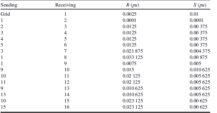
Table 2.9 provides the capacity of the DG sources and summarizes their bids. The efficiency of the fuel consuming units and the depreciation time for their installation have been taken into account, as shown in Table 2.10. The term c i denotes the payback compensation of the investment for each hour of operation for fuel consuming units. For renewable energy sources, the investment payback corresponds to term b i. For simplicity, term a i is assumed to be zero.
Table 2.9 Installed DG sources

Table 2.10 Bids of the DG sources

The depreciation time and values for installation cost are summarized in Table 2.11. In all cases, the interest rate is 8%. Both micro-turbine and fuel cell are assumed to run on natural gas whose efficiency is 8.8 kWh/m3 [11]. For the microturbine the efficiency is assumed to be 26% for burning natural gas, while the efficiency of a fuel cell is assumed to be 40% [12].
Table 2.11 Financial data for determining the bids

Data from [12,13,16] has been used for the life time of the DG and the installation cost, as summarized in Table 2.11. Using (Eq. 2.29) the cost per year can be calculated for every type of DG. This cost is distributed either to the operating hours of the DG sources that consume fuel or to the production of the intermittent DG units such as wind turbines or PV. For MT and FC, we have assumed that they operate for 90% of the year or 7884 hours. For WT, we have assumed 40% capacity factor which means 3504 kWh/kW and for the PVs the yearly production is 1300 kWh/kW according to [16].
i is the interest rate, n the depreciation time in years, InsCost, the installation cost and Ann_Cost is the annual cost for depreciation.
1. More Microgrids. [Online] www.microgrids.eu .
2. Lasseter, R., Akhil, A., Marnay, C.et al. (2002) White Paper on Integration of Distributed Energy Resources. The CERTS Microgrid Concept. CA: Tech. Rep. LBNL-50829, Consortium for Electric Reliability Technology Solutions (CERTS).
3. Katiraei, F.et al. (2008) Microgrids management. IEEE Power and Energy Magazine, 6, 54–65.
4. W3C. [Online] http://www.w3.org/ .
5. Charytoniuk, W. and Chan, M.S. (2000) Short-term load forecasting using Artificial Neural Networks. A review and evaluation. IEEE T. Power Syst., 15 (1), 263–268.
6. Steinherz Hippert, H., Pedreira, C.E. and Souza, C.S. (2001) Neural Networks for short-term load forecasting, a review and evaluation. IEEE T. Power Syst., 16 (1), 44–55.
7. Taylor, J. (2008) An evaluation of methods for very short-term electricity demand forecasting using minute-by-minute British data. Int. J. Forecasting, 24, 645–658.
8. Anemos project. [Online] http://www.anemos-project.eu.
9. Giebel, G., Kariniotakis, G. and Brownsword, R., The State-of-the-art in short-term prediction of wind power. A literature overview. Deliverable Report D1.1 of the Anemos project (ENK5-CT-2002-00665), available online at http://anemos.cma.fr.
10. Liu, K.et al. (1996) Comparison of very short-term load forecasting techniques. IEEE T. Power Syst., 11 (2), 877–882.
11. Canu, S., Duran, M. and Ding, X. (1994) District heating forecast using artificial neural networks. Int. J. Eng., 2 (4).
12. Paravan, D., Brand, H.et al. (2002) Optimization of CHP plants in a liberalized power system. Proceedings of the Balkan Power Conference, vol 2, pp. 219–226.
13. Nogales, F.J.et al. (2002) Forecasting next-day electricity prices by time series models. IEEE T. Power Syst., 17 (2), 342–348.
14. García-Martos, C., Rodríguez, J. and Sánchez, M.J. (2011) Forecasting electricity prices and their volatilities using unobserved components. Energ. Econ., 33, 1227–1239.
15. Sideratos, G. and Hatziargyriou, N. (2012) Probabilistic wind power forecasting using radial basis function neural networks. IEEE T. Power Syst., 27, 1788–1796.
16. Pinson, P. and Kariniotakis, G. (2004) Uncertainty and Prediction Risk Assessment of Short-term Wind Power Forecasts. Delft, The Netherlands: The Science of Making Torque from Wind.
17. Tsikalakis, A.G. and Hatziargyriou, N.D. (2008) Centralized control for optimizing microgrids operation. IEEE T. Energy Conver., 23 (1), 241–248.
18. Hatziargyriou, N.D., Dimeas, A. and Tsikalakis, A. (2005) Centralised and decentralized control of microgrids. Int. J. Distr. Energ. Resour., 1 (3), 197–212.
19. Tsikalakis, A.G. and Hatziargyriou, N.D. (2007) Environmental benefits of distributed generation with and without emissions trading. J. Energ. Policy, 35 (6), 3395–3409.
20. Rao, S.S. (1996) Chapter 7, in Engineering Optimization, Theory and Practice, John Wiley & Sons, New York.
21. Papadogiannis, K.A., Hatziargyriou, N.D. and Saraiva, J.T. (2003) Short Term Active/Reactive Operation Planning in Market Environment using Simulated Annealing, ISAP, Lemnos, Greece.
22. Lee, K.Y. and El-Sharkawi, M.A. (2002) Tutorial Modern Heuristic Optimization Techniques with Applications to Power Systems, IEEE PES., Chicago.
23. Papathanassiou, S., Hatziargyriou, N. and Strunz, K. (2005) A Benchmark LV microgrid for Steady State and Transient Analysis. Cigre Symposium “Power Systems with Dispersed Generation”, Athens, Greece..
24. Kariniotakis, G.N., Stavrakakis, G.S. and Nogaret, E.F. (1996) Wind power forecasting using advanced neural networks models. IEEE T. Energy Conver., 11 (4), 762–767.
25. APX. Amsterdam Power Exchange. [Online] http://www.apx.nl.
26. McArthur, S.D.J.et al. (2007) Multi-agent systems for power engineering applications— Part I: concepts, approaches, and technical challenges. IEEE T. Power Syst., 22 (4), 1743–1752.
27. McArthur, S.D.J.et al. (2007) Multi-agent systems for power engineering applications—Part II: technologies, standards, and tools for building multi-agent systems. IEEE T. Power Syst., 22 (4), 1753–1759.
28. Ferber, J. (1999) Multi-Agent Systems. An introduction to Distributed Intelligence, Addison-Wesley.
29. Bradshaw, J.M. (1997) Software Agents, MIT Press.
30. Wooldridge, M. (2009) An Introduction to Multi-agent Systems, 2nd edn, John Wiley & Sons.
31. Dimeas, A.L., Hatzivasiliadis, S.I. and Hatziargyriou, N.D. (2009) Control agents for enabling customer-driven microgrids. IEEE, Power & Energy Society General Meeting, PES'09, IEEE.
32. JADE website. [Online] www.jade.tilab.com.
33. FIPA website. [Online] www.fipa.org.
34. CIM. IEC 61970. [Online] http://www.iec.ch/smartgrid/standards/.
35. UML. [Online] http://www.uml.org.
36. Bertsekas, D.P. (1992) Auction algorithms for network flow problems: a tutorial introduction. Comput. Optim. Appl., 1, 7–66.
37. Castanon, D.P. and Bertsekas, D.A. (1992) A forward/reverse auction algorithm for asymmetric assignments problems. Comput. Optim. Appl., 1, 277–297.
38. Dimeas, A. and Hatziargyriou, N.D. (2005) Operation of a multi-agent system for microgrid control. IEEE T. Power Syst., 20 (3), 1447–1455.
39. Dayan, P. and Watkins, C.J. (1992) Q-learning. Mach. Learn., 8, 279–292.
40. Veloso, M. and Peter, S. (1999) Opaque-Transition Reinforcement Learning. Proceedings of the Third International Conference on Autonomous Agents.
41. Dimeas, A.L. and Hatziargyriou, N.D. (2010) Multi-agent reinforcement learning for microgrids. IEEE, Power and Energy Society General Meeting.
42. Gibbons, R. (1992) Game Theory for Applied Economists, Princeton University Press, Princeton, New Jersey.
43. Fudenberg, D. and Tirole, J. (1991) Game Theory, MIT Press, Cambridge, Massachusetts.
44. Korres, G.N., Hatziargyriou, N.D. and Katsikas, P.J. (2011) State estimation in multi-microgrids. Euro. Trans. Electr. Power Special Issue: Microgrids and Energy Management, 21 (2), 1178–1199.
45. Ghosh, A.K., Lubkeman, D.L. and Jones, R.H. (1997) Load modeling for distribution circuit state estimation. IEEE T. Power Deliver., 12 (2), 999–1005.
46. Kelley, A.W. and Baran, M.E. (1994) State estimation for real-time monitoring of distribution systems. IEEE T. Power Syst., 9 (3), 1601–1609.
47. Thornley, V., Jenkins, N. and White, S. (2005) State estimation applied to active distribution networks with minimal measurements. 15th Power Systems Computation Conference, Liege, Belgium: August 2005.
48. Ghosh, A.K., Lubkeman, D.L., Downey, M.J. and Jones, R.H. (1997) Distribution circuit state estimation using a probabilistic approach. IEEE T. Power Syst., 12 (1), 45–51.
49. Singh, R., Pal, B.C. and Jabr, R.A. (2009) Choice of estimator for distribution system state estimation. IET Gener. Transm. Distrib, 3 (7), 666–678.
50. Exposito, A.G. and Abur, A. (2004) Power System State Estimation: Theory and Implementation, Marcel Dekker, New York.
51. Monticelli, A. (1999) State Estimation in Electric Power Systems: A Generalized Approach, Kluwer Academic Publishers, Boston, US.
52. Wang, H. and Schulz, N.N. (2006) Using AMR data for load estimation for distribution system analysis. Electr. Pow. Syst. Res., 76, 336–342.
53. Wang, H. and Schulz, N.N. (2001) A load modelling algorithm for distribution system state estimation. Conference and Exposition in Transmission and Distribution, vol. 1 102–105.
54. Samarakoon, K., Wu, J., Ekanayake, J. and Jenkins, N. (2011) Use of Delayed Smart Meter Measurements for Distribution State Estimation. IEEE PES General Meeting, July 2011.
55. Gu, J.W., Clements, K.A., Krumpholz, G.R. and Davis, P.W. (1983) The solution of ill-conditioned power system state estimation problems. IEEE T. Power Ap. Syst., PAS-102, 3473–3480.
56. Korres, G.N. (2011) A distributed multiarea state estimation. IEEE T. Power Syst., 26, 73–84.
57. Gomez-Exposito, A., de la Villa Jaen, A., Gomez-Quiles, C.et al. (2011) A taxonomy of multi-area state estimation methods. Electr. Power Syst., 81 1060–1069.
58. Cobelo, I., Shafiu, A., Jenkins, N. and Strbac, G. (2007) State estimation of networks with distributed generation. Eur. Trans. Electr. Power, 17, 21–36.
59. Su, C.-L. and Lu, C.-N. (2001) Interconnected network state estimation using randomly delayed measurements. IEEE T. Power Syst., 16 (4), 870–878.
60. Korres, G.N. and Manousakis, N.M. (2012) A state estimation algorithm for monitoring topology changes in distribution systems. PES General Meeting, San Diego, CA, USA, 2012, pp. 1–7.
61. Pereira, J. (May 2009) A state estimation approach for distribution networks considering uncertainties and switching. Porto: Faculdade de Engenharia da Universidade do Porto. PhD Thesis, July 2001 [Online] http://saca.inescporto.pt/artigos/artigo150.pdf.
62. Katsikas, G.N. and Korres and, P.J. (2002) Identification of circuit breaker statuses in WLS state estimator. IEEE T. Power Syst., 17 (3), 818–825.
63. Saric, A.T. and Ciric, R.M. (2003) Integrated fuzzy state estimation and load flow analysis in distribution networks. IEEE Trans. Power Delivery, 18 (2), 571–578.
64. Konjic, T., Miranda, V. and Kapetanovic, I. (2005) Fuzzy inference systems applied to LV substation load estimation. IEEE T. Power Syst., 20 (2), 742–749.
65. Miranda, V., Pereira, J. and Saraiva, J.T. (2000) Load allocation in DMS with a fuzzy state estimator. IEEE T. Power Syst., 15 (2), 529–534.
66. Zadeh, L.A. (1965) Fuzzy Sets. Inform. Control, 8, 338–353.
