5
Operation of Multi-Microgrids
5.1 Introduction
This chapter aims to study the management of distribution networks with an increased microgrid penetration, that is, corresponding to a situation where most of the low voltage (LV) networks turn into active microgrids. It is therefore assumed that the microgrid concept is extended, leading to the development of a new concept – the multi-microgrid [1]. A full exploitation of this concept involves the design of a new control architecture as well as the development of new management tools or the adaptation of existing distribution management systems (DMS) tools.
The novel concept of multi-microgrids corresponds to a high-level structure, formed at the medium voltage (MV) level, consisting of several LV microgrids and distributed generation (DG) units connected to adjacent MV feeders. For the purpose of grid control and management, microgrids, DG units and MV loads under active demand-side management control can be considered as active cells in this type of power system. In this new scenario, the possibility of having some MV responsive loads able to receive control requests under a load curtailment strategy is regarded as a way to ensure additional ancillary services.
A large number of LV networks with microsources and loads, that are no longer passive elements of the distribution grid, then need to be operated together in a coordinated way. Therefore, the system to be managed increases largely in complexity and dimension, requiring a completely new control and management architecture. This architecture is illustrated in Figure 5.1.
Figure 5.1 Control and management architecture of a multi-microgrid system
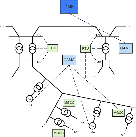
An effective management of this type of system requires the development of a hierarchical control architecture, where control will be exercised by an intermediate controller – the central autonomous management controller (CAMC) – to be installed at the MV bus level of a high voltage (HV)/MV substation, under the responsibility of the distribution system operator (DSO) and will be in charge of a multi-microgrid system. In this way, the complexity of the system can be shared among several smaller individual control agents, behaving like a small DMS that is able to tackle the scheduling problem of generating units (DG and microsources) and other control devices that are installed in the system in both normal and emergency conditions.
In this context, the deployment of a communications infrastructure as a means for achieving full observability of the distribution network is crucial. This can be achieved by exploiting a smart metering infrastructure, which will allow a coordinated and integrated management of individual elements at the LV level, such as microgrids (and corresponding microgenerators, loads and storage devices). DG units and loads participating in active demand-side management strategies, directly connected to the MV grid, may require a dedicated communication infrastructure. This local communication infrastructure will be the key driver for managing the distribution network in a more efficient way and consequently maximizing the integration of DG and microgeneration, especially renewable-based power sources.
5.2 Multi-Microgrid Control and Management Architecture
The development of the microgrid concept has led to the need for a detailed analysis of the interaction between the microgrid central controller (MGCC) and the central DMS (operated by the DSO), which is in charge of the whole distribution network, in both normal and emergency operating modes. This has already been addressed in Chapter 2, and several other publications also describe it [2,3].
However, as previously seen, the new concept of multi-microgrids is related to a higher-level structure, formed at the MV level, consisting of LV microgrids and DG units connected to adjacent MV feeders.
Nowadays, the DMS is wholly responsible for the supervision, control and management of the whole distribution system. In the future, in addition to this central DMS, there may be two additional management levels:
- HV/MV substation level, where a new management agent, the CAMC, will be installed as illustrated in Figure 5.1. – the CAMC will accommodate a set of local functionalities that are normally assigned to the DMS (as well as other new functionalities) and will be responsible for interfacing the DMS with lower-level controllers.
- microgrid level, where the MGCC to be housed in MV/LV substations will be responsible for managing the microgrid, including the control of the microsources and responsive loads – voltage monitoring in each LV grid will be performed using the microgrid communication infrastructure.
Similarly to what happens in the microgrid concept, in multi-microgrid systems, two modes of operation and operating state may be envisaged. These two possible operating modes are:
- normal operating mode – when the multi-microgrid system is operated interconnected to the main distribution grid.
- emergency operating mode – when the multi-microgrid system is operated in an autonomous mode (islanded from the main power system) or, following a blackout, when the multi-microgrid system is contributing to service restoration by triggering a black start procedure.
The main issue when dealing with control strategies for multi-microgrid systems is the use of individual controllers, which should have a certain degree of autonomy and be able to communicate with each other in order to implement specific control actions. A partially decentralized scheme is justified by the tremendous increase in both dimension and complexity of the system so that the management of a multi-microgrid system requires the use of a more flexible control and management architecture.
Nevertheless, decision-making – even with some degree of decentralized control – should still adhere to a hierarchical structure. A central controller should collect data from multiple devices and be able to establish rules for low-rank individual controllers. These actions must be set by a high-level central controller (the DMS), which ought to delegate some tasks to other lower-level controllers (either the CAMC or the MGCC). This is because central management would not be effective owing to the large amount of data to be processed, and therefore would not allow autonomous management, namely during islanded mode of operation. The CAMC must then have the ability to communicate with other local controllers (such as MGCCs, or directly with DG sources or loads connected to the MV network), serving as an interface for the main DMS.
Consequently, the CAMC plays a key role in a multi-microgrid system as it will be responsible for the data acquisition process, for enabling the dialog with the DMS located upstream, for running specific network functionalities and for scheduling the different resources in the downstream network. In this context, existing DMS functionalities need to be upgraded due to the operational and technical changes that result from the adoption of the multi-microgrid concept, especially the introduction of the CAMC, and corresponding hierarchical control architecture.
The management of the multi-microgrid (MV network included) will be performed through the CAMC. This new controller will also have to deal with technical and commercial constraints and contracts, in order to manage the multi-microgrid both in HV grid-connected operating mode and in emergency operating mode, as previously seen. A set of functionalities to integrate the CAMC is shown in Figure 5.2.
Figure 5.2 Central autonomous management controller functionalities
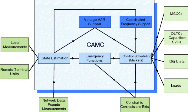
It is important to stress that all these functionalities may not be available in all multi-microgrid systems. Their availability will depend very much on the type of network considered and on the characteristics of local DG units, as well as on the active load demand-side resources availability.
Furthermore, in multi-microgrid systems, microgrids – together with MV-grid connected DG units – can participate in the provision of ancillary services, such as coordinated voltage support, with a significant impact on the electrical distribution system operation and also regarding its local dynamic behavior.
The need to study the dynamic behavior of a multi-microgrid, to evaluate the islanding feasibility, involves dealing with hundreds (or even thousands) of microgenerators, which may lead to a significant computational burden when developing these simulations. So dynamic equivalents for microgrids are of utmost importance for developing such studies.
Several key aspects of multi-microgrid operation, developed within the framework of the EU R&D project, More Microgrids [4,5], are addressed in the following sections, namely regarding some of the most important functionalities available at the CAMC level. Bearing in mind the relevance of some of these functionalities and the need to perform some of the key studies, such as dynamic behavior analysis, the following topics are addressed:
- coordinated voltage/var support for normal operation,
- coordinated frequency control for islanded operation,
- local black start – restoration of the MV grid following a blackout,
- definition of dynamic equivalents for microgrids.
5.3 Coordinated Voltage/var Support
5.3.1 Introduction
Large-scale integration of DERs (DG in particular) may pose serious operational problems for the DSO. One of the major concerns that arises is related to the voltage rise effect as a result of the massive presence of these generation units in the distribution system, namely in LV networks [6]. In these systems, conventional voltage regulation methods are not suited for tackling this problem effectively as they do not address variable power injections provided by DG units, so voltage control is an issue that must be dealt with efficiently.
Due to operational issues, most DSOs require that DGs operate at zero reactive power or at a fixed power factor. This limits the amount of DG installed capacity, in order to guarantee admissible voltage profiles in the worst-case scenario. Several approaches can be found in the scientific literature that address voltage control in distribution grids with the presence of DG. However, these proposals do not take into consideration coordinated operation at MV and LV levels and/or the specific characteristics of distribution networks.
Consequently, new approaches for voltage control must be developed, based on the full use of the resources available, especially DG and microgeneration units, taking into account the specific characteristics of distribution networks (in particular, LV grids that usually have very resistive lines). This is particularly important in the case of LV networks where both active and reactive power control is needed for an efficient voltage control scheme. In some extreme cases, if no local storage is available, it may even be necessary to spill some local generation in order to avoid voltage rise problems [7].
5.3.2 Mathematical Formulation
A hierarchical coordinated approach for voltage/var control in distribution systems with high penetration of DG can be formulated as a multi-objective optimization problem. The proposed formulation of this problem aims at minimizing active power losses and microgeneration curtailment, subject to a set of technical and operational constraints such as voltage and line loading levels [8].
The main control variables identified are: reactive power from MV-connected DG sources, on-load tap changing (OLTC) transformer tap settings and microgeneration curtailment. Consequently, this problem becomes a mixed integer, nonlinear optimization problem, since it deals with both continuous and discrete variables.
The objective function and the constraints used to solve this problem are presented below.
(5.1) ![]()
(5.2) ![]()
(5.3) ![]()
(5.4) ![]()
(5.5) ![]()
(5.6) ![]()
(5.7) ![]()
Where
Considering the specificities of the voltage control problem, particularly the fact that it comprises both discrete variables (transformer taps) and continuous variables (active or reactive power generation), a meta-heuristic approach –evolutionary particle swarm optimization (EPSO) – was used to find the solution to the problem. EPSO is a hybrid method based on two already well-established meta-heuristic optimization techniques: evolutionary strategies [9] and particle swarm optimization [10]. Several applications of EPSO to power system operation can be found in [11,12].
5.3.3 Proposed Approach
In order to develop an efficient coordinated method for voltage support in distribution grids, involving the MV and LV levels, the specific characteristics of these MV and LV networks must be considered. Concerning the MV network, a traditional power flow routine may be used to assess the impact of DG and microgeneration. However, for an LV system comprising single-phase loads and microgeneration units that cause phase imbalance, traditional power flow routines are not suitable. For this type of systems, a three-phase power flow must be employed in order to evaluate the expected impacts in the operation of the LV grid.
Furthermore, the main problem when dealing with optimizing distribution network operation is the dimension of the distribution system. Given the size of both MV and LV real distribution networks, a full representation of an MV network (including all LV feeders located downstream) is impractical. Since the dimension of the system may be huge, considering that an MV including the downstream LV networks can have several thousand buses, it becomes practically unfeasible to develop an algorithm using a full model representation of the MV and LV levels, able to operate in a real-time management environment.
Therefore, a decoupled approach was adopted that allows modeling in detail only those LV networks considered as critical in terms of microgeneration penetration levels. In this approach, from the MV point of view, each active microgrid is considered as a single bus with an equivalent generator (corresponding to the sum of all microgeneration) and equivalent load (corresponding to the sum of all LV loads), and passive LV networks are modeled as a non-controllable load as can be observed in Figure 5.3.
Figure 5.3 Decoupled modeling approach used for MV and LV networks
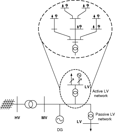
On the other hand, the effects of the control actions must be assessed at the LV level, especially in the case of “active” LV networks. This means that a detailed representation of these networks should be used in order to know the behavior of the main operation parameters, such as voltage profiles. This is extremely relevant since voltage profiles in LV networks with large-scale microgeneration integration tend to be high. The decoupled approach followed in this work allows modeling in detail only those LV networks considered as critical in terms of microgeneration penetration levels.
As a result, in order to speed up the integrated control algorithm, an artificial neural network (ANN) model able to emulate the behavior of the active microgrid was adopted. This option enables the use of the optimization tool employed in real-time operation, by reducing the long simulation times that are required in order to calculate consecutive LV power flows. In fact, the ANN can be regarded as an equivalent model, able to reproduce the steady-state behavior of the LV network, thus allowing the rapid evaluation of voltage profiles and other variables. Using the ANN, the computational burden – and consequently the computational time – required to run the application can be significantly reduced.
5.3.4 Microgrid Steady-State Equivalents
As previously mentioned, an ANN model able to emulate the behavior of an active microgrid for steady-state analysis has been developed. Therefore, each active microgrid can be replaced by an equivalent ANN model in the global optimization procedure as illustrated in Figure 5.4.
Figure 5.4 Neural network model for emulation of a microgrid in steady-state analysis
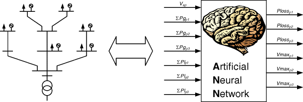
In this case, ANN models for each feeder of each LV network were developed, since it was observed that feeders may include different amounts of microgeneration and therefore the cause for an overvoltage may be originated from one single feeder with excessive microgeneration integration.
In Figure 5.4
In order to generate the dataset corresponding to the inputs chosen to train the ANN, a large number of three-phase power flows must be computed, considering different combinations of the inputs (i.e. several values for the voltage reference at the MV/LV transformer, for the power produced by each microgenerator and for the load), in order to calculate the active power losses and assess the voltage profiles in each of these scenarios.
For this purpose, a three-phase power flow routine was developed in order to enable the analysis of the steady-state behavior of LV networks, considering their specific characteristics: phase imbalances due to the connection of single-phase loads and single-phase microgeneration units exploiting different technologies.
The power flow solution method used is based on the one presented in [13] and is used for three-phase, four-wire radial distribution networks relying on a backward–forward technique, which is extremely fast to reach convergence.
From the tests that were performed, it was seen that the ANN with best performance was a two-layer feed-forward ANN with sigmoid hidden neurons and linear output neurons. Still, it must be pointed out that in case there is a change in topology of the “active” LV network, a new ANN must be computed. This means that it is necessary to update the data and generate a new dataset, followed by a retraining of an updated ANN, which may be considered as a drawback of this method.
In order to efficiently use the approach developed, it is necessary to automate the procedure of retraining the ANNs. First of all, the main changes that trigger the need for retraining the ANNs must be identified. These changes are mostly changes in the topology of the networks due to the inclusion (or removal) of additional DGs, microgeneration units or loads, the set-up (or upgrade) of a line or transformer and the expansion of the LV grid.
5.3.5 Development of the Tool
The algorithm developed for voltage control is designed to be used as an online function available for the DSO. This algorithm is intended to be integrated as a software module that will be housed in the CAMC.
Exploiting the communication infrastructure available in multi-microgrids, the CAMC will be able to collect critical information from the several devices in the network, namely data from load and RES forecast modules and generation dispatch, in order to assess voltage profiles, branch overload levels and active power losses. Using this information, the voltage control algorithm is run and, after it has successfully terminated, produces a set of commands in the form of setpoints. These commands are then sent to the several devices such as DG units, microgeneration units (via the corresponding MGCC) and OLTC transformers. This procedure is intended to run periodically and in an automated way, under the supervision of the DSO.
The topology and structure of the MV and LV distribution systems is also periodically updated in order to provide the various modules with data on the current status of the grid, including all devices such as DG units, microgenerators, loads and switches.
5.3.6 Main Results
The algorithm was tested using real Portuguese MV and LV distribution networks, considering expected future scenarios for the integration of DG and microgeneration units at the MV and LV level, respectively. These networks are presented and described in [7].
It was observed that the developed control approach is able to maintain secure operating conditions without the violation of technical constraints, namely in terms of voltage profiles. Figure 5.5 shows the daily profile of active power losses before and after running the voltage control algorithm.
Figure 5.5 Total active power losses in the MV network
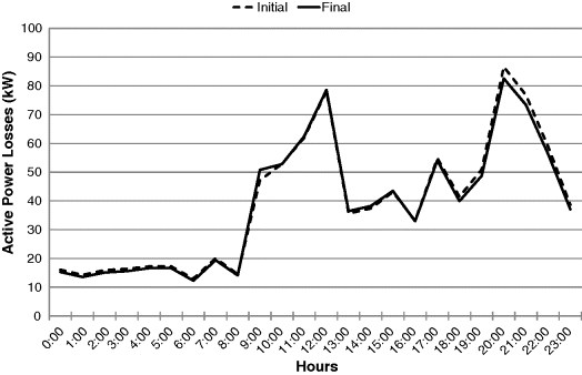
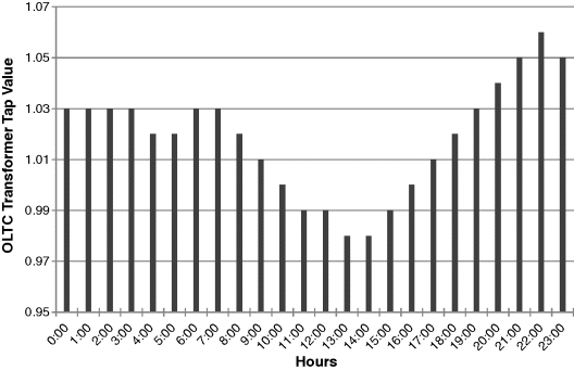
Figure 5.6 shows the tap values at the OLTC transformer. According to the modeling of the transformer with taps on the secondary side, tap values above 1 raise the voltage on the secondary of the transformer. Consequently, lower tap values are used when voltage profiles are typically high and vice versa. As can be observed, the constraint used for limiting the number of switching actions of the OLTC transformer meant that, in consecutive one-hour periods, only one tap change from one period to the other was required.
Figure 5.6 Tap changes in OLTC transformer
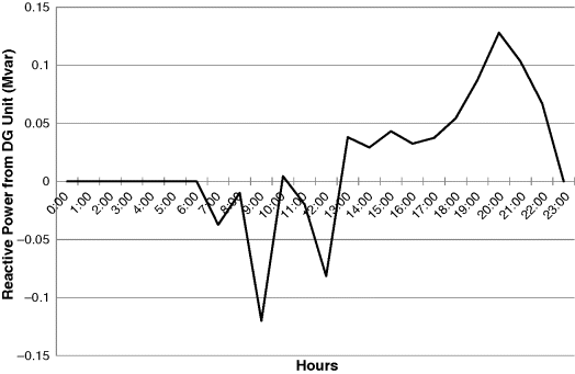
Furthermore, the contribution of a MV-connected DG unit for voltage support is presented in Figure 5.7. The DG units were used to supply reactive power (positive values) or to absorb reactive power (negative values), according to the operation scenario requirements. It can be observed that the DG unit tends to absorb reactive power during daytime, when generation profiles are high, and voltage values are above the admissible limits. Conversely, during nighttime, the DG unit supplies reactive power in order to raise voltage profiles and help in reducing active power losses.
Figure 5.7 Reactive power from MV-connected DG unit
For the case analyzed, without voltage control, voltage values in some feeders were above the admissible range of +5% owing to the PV-based microgeneration, which is generating near its peak capacity. In this case, the PV panels generate power at peak capacity around 13:00, which is outside the peak demand hours and in some cases forces excess generation through the MV/LV transformer, causing reverse power flows.
However, using the voltage support algorithm developed, it was possible to bring these values back to an admissible range of operating conditions by curtailing some excess microgeneration in the problematic LV feeders during some critical hours of the day.
Figure 5.8 shows the case of a feeder with moderate integration of PV microgeneration. In Figure 5.8a the maximum voltage value in an LV feeder for each hour of the day is presented. It shows that the voltage value at 13:00 was slightly above the admissible limit. Therefore, it was necessary to curtail a small amount of PV microgeneration in order to bring the voltage back into the admissible range (Figure 5.8b).
Figure 5.8 (a) Maximum voltage values in LV feeder 1 (b) Microgeneration curtailment in LV feeder 1
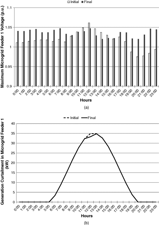
Figure 5.9 presents a case with large integration of PV microgeneration. In this case, it was necessary to curtail PV microgeneration at various times of the day in order to ensure that there were no voltage violations.
Figure 5.9 (a) Maximum voltage values in LV feeder 3 (b) Microgeneration curtailment in LV feeder 3
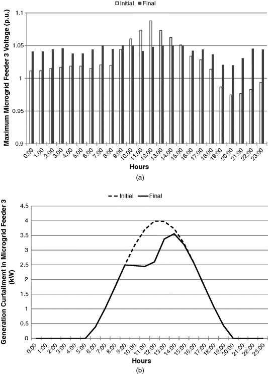
It must be stressed that for the formulation proposed, microgeneration curtailment is used as a final resort, only if the other control actions (namely tap settings in the OLTC transformers) are insufficient to reduce voltage levels in order to keep the maximum possible integration of RES. This is done empirically by adjusting the decision parameter α, which reflects the preferences of the decision-maker, which in this case is assumed to be the DSO. Here, a low value for the decision parameter α was used, which reflects the preference of the DSO in valuing more the minimization of microgeneration curtailment than the reduction of active power losses.
5.4 Coordinated Frequency Control
As previously seen, a multi-microgrid system can be operated in either normal or emergency mode, that is, connected to the upstream HV network or isolated from it, respectively. Islanded operation is allowed in a multi-microgrid, since there is local generation capability and some loads can also be managed during these operating conditions. For this purpose, local primary frequency control is assumed to be implemented in some microgeneration units and a secondary frequency control is also supposed to be available. In addition, a hierarchical frequency control system is housed in the CAMC. Therefore, the CAMC controls the MGCCs, the independent DG units and the controllable MV loads. The MGCCs act as an interface between the CAMC and the internal components of the microgrids, so that the CAMC does not need to have the detailed knowledge of their constitution.
When the multi-microgrid is operated in interconnected mode, the CAMC intervention is kept to a minimum, managing only the load flow on the interconnection with the upstream HV network according to the requests sent by the DMS. However, when the multi-microgrid system is operated in islanded mode, the hierarchical control scheme implemented in the CAMC plays a key role and is responsible for managing the whole multi-microgrid, autonomously controlling the system frequency and thus improving the continuity of service following a fault or programmed maintenance actions on the upstream HV network.
In islanded operation, the CAMC will respond to power system frequency changes in a way similar to the one implemented in regular automatic generation control (AGC) functionalities [14]. A proportional-integral (PI) controller can be used to derive the requested global power change needed to restore system frequency. Then, a set of criteria (e.g., economic) will allocate individual contributions to the various power generation units, controllable MV loads and MGCCs under CAMC control [15]. Each of the MGCCs will then allocate the necessary power changes to its subordinate controllable loads and microgeneration units, through the local load and microgeneration controllers.
5.4.1 Hierarchical Control Overview
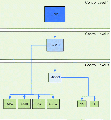
The hierarchical control system can be represented by the block diagram in Figure 5.10. When dealing with a single autonomous multi-microgrid (a single MV network) only control levels 2 and 3 need to have their function studied or simulated. The need to analyze any functions related to the DMS only arises while dealing with several MV networks at once, with more than one supervised by this DMS.
Figure 5.10 Hierarchical control scheme of a multi-microgrid system
5.4.1.1 Control Level 2 – CAMC
As mentioned earlier, the commands needed to modify power generation and loads originate in the CAMC. These commands are sent to MGCCs, to local DG units and also to controllable MV loads. MGCCs act as an interface between the CAMC and the internal active components of the microgrids, so that the CAMC doesn't need to have the details of each microgrid's constitution.
While the MV multi-microgrid is connected to the upstream HV network, the CAMC limits its autonomous intervention to a minimum. However, in islanded operation, the CAMC will step in and respond to power system frequency changes in a way similar to that implemented in regular AGC functionalities. A PI controller is then used to derive the requested global power change needed to restore system frequency. Then, an economic allocation algorithm will allocate contributions for this power change to the various power generation units, controllable MV loads and MGCCs under CAMC control, but only if they are willing, at that point in time, to participate in frequency regulation. Instead of strictly economic criteria, it is of course possible to use another different criterion or combination of criteria.
It should be noted that the CAMC will only act if strictly required, and will not try to globally change setpoints in order to achieve a near optimum point of operation of the whole multi-microgrid. This justifies the choice of using power setpoint variations and not absolute power setpoints. Using power setpoint variations provides a simple way to have a higher-order control system, either automatic or manual, that would independently adjust microsource or DG output to setpoints other than the system optimal ones. One example of this “control system” could be the microsource individual owners who would adjust microturbines, for instance, according to their heating needs.
5.4.1.2 Control Level 3 – MGCC
Each of the MGCCs will also allocate the necessary power changes to its subordinate controllable loads and microgeneration units, through the load controllers (LC) and microsource controllers (MC). Some of these microsources do not usually have full regulation capabilities and will not normally be asked to change power generation. This can be the case for both PV and wind generation, due to limitations in primary resource availability. In this case, however, it is possible to consider that generation can be curtailed in case of an excess power imbalance.
5.4.1.3 Load-Shedding
The approach adopted for load-shedding, in the context of this hierarchical control system, is fairly different from the one used in conventional systems, because the hierarchical control system which supervises the controllable loads isn't capable of acting in near instantaneous time frames (mainly owing to communication system limitations). Therefore, in these circumstances, load-shedding is not expected to reduce the amplitude of the frequency excursions in the few seconds following a disturbance. It should be seen more as a kind of secondary reserve – rather than an emergency resource – helping the frequency to return to the rated value faster or without depending so much on the availability of renewable resources or other generation systems.
The main difference that distinguishes microsources from controllable loads is that it is not feasible to keep loads disconnected indefinitely (except for this detail, loads could be regarded simply as negative generation). It is thus mandatory to reconnect as much load as possible after the system returns to a near normal frequency value. This is accomplished through the use of a control loop that runs on a larger timescale, reconnecting loads after the system has been running at a near steady-state condition for a predefined period of time.
Starting from the assumption that the system – after some time of running stable and near the rated frequency – is capable of supporting the connection of further loads, the control systems starts to reconnect the most expensive/important ones first. This is done step by step, always ensuring that there is enough available reserve on the multi-microgrid in order not to unnecessarily compromise the system's stability. Before each new reconnection, the control system waits for the frequency to stabilize.
5.4.1.4 Energy Storage Systems
A cluster of several storage devices (e.g. flywheels and batteries) could, if integrated into the hierarchical control system, efficiently establish a storage reserve that would be of great help to the islanded operation of the network at both the microgrid and the multi-microgrid level. Also, we are assuming that most of these storage devices have interface inverters of the voltage source inverter (VSI) type, which can have their output power controlled on the basis of frequency droop.
Therefore, these storage devices can help in two possible ways: (a) they can act autonomously, with their output power P VSI responding to system frequency changes, providing energy used to initially balance the system using a proportional control element as described next or (b) they can receive setpoints controlled from a central location, in a hierarchical way.
![]()
These two control methods are not mutually exclusive: while an autonomous response will undoubtedly improve the system's response to the initial frequency deviations following a disturbance, the hierarchical system can take over after that initial response and reallocate each source and storage element contribution according to some predefined criteria. This two-step approach can be justified by the intrinsically slow nature of the hierarchical control system, which suggests that grid-connected storage devices under hierarchical control should be regarded as a secondary reserve while, at the same time, they should be capable of acting autonomously in order to be able to limit initial frequency excursions.
5.4.2 Hierarchical Control Details
In this approach, the system's frequency is continuously monitored by the CAMC (Figure 5.11). Every time interval Ts (sample time), if triggered by significant changes in frequency, the CAMC will send control setpoints to every MGCC, other DG units and controllable loads. This sample time Ts cannot be very small, mainly because of the constraints imposed by the communication system on which this control system depends.
Figure 5.11 Implementation flowchart
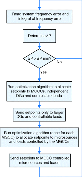
Therefore, the frequency error and the frequency error integral will be used to determine the additional power ΔP to be requested to the available contributors under CAMC control: MGCCs, DG units and controllable loads. This approach effectively implements a kind of PI controller.
(5.8) ![]()
It should be noted that this additional power can have negative values if the frequency rises above its rated value. In this way, the CAMC can also respond to other disturbances, such as load loss while in islanded mode, instructing the distributed generation to reduce power output (including microgeneration curtailment, if necessary), eventually reconnecting some loads still disconnected at the moment.
If the required power variation ΔP is larger than a predefined threshold (related to a deadband), the control system will proceed to determine how to optimally distribute the power requests through the available sources. Unitary generation costs for each of the sources (MGCCs and other DG units) can be used for this purpose.
The optimization can be based on standard linear optimization techniques:
(5.9) ![]()
(5.10) ![]()
(5.11) ![]()
(5.12) ![]()
Where the vectors represent
The set of restrictions can also define which generators/loads participate in frequency regulation. This can be done by setting to zero the i th elements of both b 1 and b 2, corresponding to units that cannot be adjusted.
Because loads are considered as negative generation, the corresponding coefficients (elements in vector c of prices) are negative.
In order to avoid globally changing setpoints (e.g. decreasing production from expensive microsources and replacing them with less expensive ones), it is necessary to adjust the lower and upper bounds in the optimization procedure according to the ΔP value:
(5.13) ![]()
The enforcement of the above described conditions ensures that no microsource will decrease its production, so that another one can increase it (i.e. there will not be any unsolicited power transfers between microsources).
This optimization is performed each sample period Ts and will originate a vector representing the power generation changes to be requested from microgrids (MGCCs), independent DG units (e.g. combined heat and power–CHP) and loads (MV load-shedding operations).
Each MGCC will now use the power change requested by the CAMC to establish the main restriction of a new optimization procedure, which could be identical to the one used before by the CAMC. This optimization will now help determine the power changes to be requested from microsources and controllable loads under MGCC control, thus one level below in the hierarchical control structure.
5.4.3 Main Results
Using the described coordinated frequency control methods, the system is able to handle severe network disturbances such as islanding events. It can also perform load-following by scheduling power generation among generation units and microgrids under its control. A dynamic simulation platform was developed for evaluation purposes and includes an extended version of the multi-microgrid test network shown in Figure 5.12 [16].
Figure 5.12 Multi-microgrid extended test network
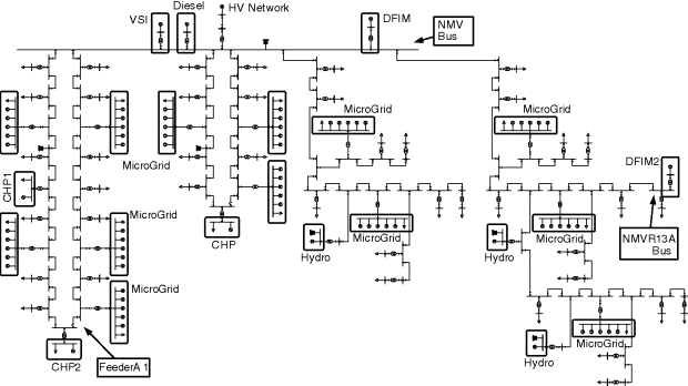
Figure 5.13 illustrates the frequency control approach described, by showing the response of the hierarchical control system to a sudden islanding and also to gradual load changes in islanded mode. In this test case, the MV multi-microgrid network has a total load of 19.9 MW and is importing approximately 5.3 MW of active power from the upstream HV network.
Figure 5.13 Test disturbances and frequency behavior with and without secondary control
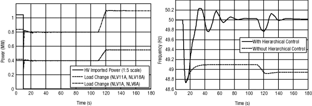
The test disturbances include the disconnection of the HV/MV branch, effectively islanding the multi-microgrid system, and also a load change at several nodes at a rate of 4% per second for 10 s (for total increase of nearly 0.9 MW). These disturbances are also pictured in Figure 5.13.
The results show how the hierarchical control adopted in this multi-microgrid manages to recover the frequency to the rated value after islanding. Although the minimum frequency value after the disturbance remains practically unaltered, in the moments that follow, the system evolves in a much better way.
The success of the frequency recovery is in part due to the fact that the CAMC is sending setpoints to the microgrids and other DG units dispersed on the MV network. The microsources inside the microgrids are also subject to setpoint attribution according to a similar price-dependent optimization algorithm. Figure 5.14 shows the microgrid setpoint modifications and how they are directly translated into individual setpoints for each of the microsources within that same microgrid.
Figure 5.14 Example microgrid external and internal setpoint commands and output power

When the multi-microgrid system does not have sufficient reserves to respond to a large loss of imported power, load curtailment may be required. This control system is designed to support these actions as well, as demonstrated in Figure 5.15.
Figure 5.15 Influence of load shedding and shedding steps during islanding

The hierarchical control algorithm is thus capable of acting on controllable loads, integrating them into the optimization process. The expected benefits include the increase in system response speed (Figure 5.15), while still complying with the optimization rules in use.
Loads are disconnected according to their “cost” or importance. Figure 5.15 (right) illustrates how load-curtailment occurs, showing two of the larger loads, but considered less important. These loads begin to be curtailed soon after the main disturbance (islanding). On the other hand, more expensive/important loads would begin to be disconnected later, after all the less expensive ones have attained their minimum values.
As mentioned, the test network contains several VSI devices coupled to storage elements. The output of VSI is based on the frequency error through the use of a proportional controller. Figure 5.16 illustrates VSI influence on the frequency variation of the sample test system, together with an example of the power output of a large VSI (connected at the MV level) and one of the microgrids' VSIs. All the previously shown simulation results benefit from the usage of the storage elements as active and autonomous participants in frequency regulation. It should be noted that the VSIs are also programmed to emulate the behavior of unregulated synchronous machines, which may mask the influence of the proportional controllers during the initial phase of heavier disturbances.
Figure 5.16 Influence of autonomous proportional control in storage devices
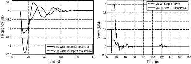
These examples show how the setpoint modification commands sent to DG units, microgrids and controllable loads enable the frequency to return to the rated value in a reasonable amount of time. In addition, the control system can resort to load-shedding, in order to better support the transition to islanded operation in scenarios of low multi-microgrid power reserves. The presence of storage devices in the network proves essential to manage the initial frequency excursion following large disturbances.
The implemented coordinated frequency control is able to cope with the islanding of a multi-microgrid system following severe upstream HV network disturbances and can be used as a form of secondary control to return the frequency to the rated value, either after islanding or for load-following purposes.
5.5 Emergency Functions (Black Start)
Following a large deployment of microgrids under the multi-microgrid concept, local self-healing techniques can be exploited, since a substantial number of microgrids and other DG units connected to the MV network can provide service restoration in its area of influence. Therefore, after a local blackout or a general blackout where the multi-microgrid was not able to isolate and continue to operate in islanded mode, it is possible to achieve a reduction of interruption times by exploiting multi-microgrid black start capabilities. These capabilities provide a fast black start concurrently at both LV and MV levels and allow multi-microgrid system islanded operation until the upstream HV network is available.
In fact, concerning the microgrid concept [17] the interruption time of LV consumers can be reduced by allowing microgrid islanded operation until the MV network is available, thus exploiting microgeneration control capabilities to provide fast service restoration at the LV level. This first step will be followed by the microgrid synchronization with MV grid when it is available. Based on microgrid control strategies and making use of the microgrid communication infrastructures, special issues for microgrid service restoration were identified in order to totally automate the microgrid restoration procedure [18,19]. Therefore, during multi-microgrid service restoration it was assumed that the MGCC of each microgrid is responsible for its service restoration and will build up the microgrid system autonomously.
Because a significant part of the full multi-microgrid restoration process can be performed in several islands in parallel, the time between grid blackout and power restoration to a substantial proportion of the consumers can be much reduced. However, the final goal of restoration is to reconstruct the multi-microgrid state existing before the loss of power, and this usually includes avoiding isolated islands, even if they are semi-autonomous microgrids. Therefore, the CAMC must also play an important role in coordinating the interconnection of all the temporary autonomous islands.
In a multi-microgrid, the rules required to accomplish a successful restoration can be more general than those that can be adopted in a HV/VHV network. This fact is almost unavoidable because MV networks can be extremely diverse as regards network characteristics and types of energy sources, power electronics interfaces and loads. Therefore, it can become difficult to find a very specific set of rules that fits every network and every operation point of a network.
The black start software module to be implemented on the CAMC is responsible for managing this set of rules and conditions to be checked during restoration. These rules and conditions define a sequence of control actions to be carried out during multi-microgrid restoration and must be coordinated and planned beforehand. For this purpose, a sequence of control actions can be identified and evaluated through numerical simulation. The proposed sequence of control actions, to be stored at the CAMC level, allows the definition of a procedure that aims at the full automation of the entire multi-microgrid service restoration procedure and subsequent synchronization with the upstream HV system.
5.5.1 Restoration Guidelines
Multi-microgrid restoration will be triggered if a general or local blackout occurs or if major disturbances affecting the HV upstream system do not allow the multi-microgrid to be supplied from the HV side after a predefined time interval. The CAMC should then be able to receive information from the DMS about the service restoration status at the HV level in order to decide about launching a black start procedure. In addition, the CAMC will guide multi-microgrid service restoration, based on information about the last multi-microgrid load and generation scenarios. This information is kept in a maintained database together with the information about restart availability of DG units connected to the MV network and is used to further adjust and refine the sequence of control actions, mostly identified in advance and embedded into the CAMC software, which will finally lead the system to a state similar to the pre-fault scenario.
The CAMC is also used for secondary frequency control during load-following conditions when the multi-microgrid is operated in islanded mode, as presented in Section 5.4. In order to balance generation and load, the CAMC generates setpoints based on system frequency changes and sends them to the MGCC and to controllable DG units. In turn, the MGCCs will act as intermediate controllers between the CAMC and the microgrid internal controllers. MGCCs are responsible for scheduling the corresponding power change among the microgeneration units by sending setpoints to the corresponding controllers.
The MGCC is also responsible for guiding the microgrid black start procedure, and so it is assumed that microgrid service restoration is carried out autonomously when the microgrid is operated in islanded mode until the MV network is available. As several islands will be formed during the early stages of the multi-microgrid black start procedure, it is also assumed that the automatic secondary frequency control system embedded into the CAMC software is initially turned off. This allows a simpler coordination of the restoration procedure, while ensuring that no contradictory commands ever arise.
Thus, the information exchange between the CAMC and local controllers during the multi-microgrid black start procedure will mainly involve switching orders. The purpose of these commands is to rebuild the MV network and also to connect DG units, microgrids and MV loads, according to general monitoring information (e.g. voltage levels, system frequency and grid status). All this information is received and processed by the CAMC through the communication infrastructure that is supposed to be available. Verification of synchronization conditions is performed locally.
Another basic requirement is the availability of DG units connected to the MV network with black start capability. Its restart procedure is carried out prior to network energization, so it is not reflected in the MV network. The same happens with the several microgrids with black start capability.
Furthermore, it is also assumed that it is possible to prepare the network for energization. To accomplish this, after system collapse, the following requirements should be taken into account:
- the multi-microgrid is disconnected from the upstream HV network,
- multi-microgrid feeders are fully sectionalized,
- microgrids are disconnected from the MV network,
- DG units and loads are disconnected from the MV network,
- the HV/MV transformer is disconnected from the HV and MV networks,
- all MV/LV transformers are disconnected from the MV and LV networks,
- all the reactive power sources, such as shunt capacitor banks, are switched off.
From this starting point, the multi-microgrid restoration procedure is carried out with the aim of supplying consumers as soon as possible, while satisfying the system operation conditions. So, after a general blackout, the CAMC will perform service restoration in a multi-microgrid based on information stored in a database about the last multi-microgrid load scenario, as described before, by performing the following generic sequence of actions (the first two steps include the actions described in the previous paragraph):
The technical feasibility of the proposed sequence of control actions, which allows multi-microgrid service restoration was evaluated using the test network presented in Figure 5.12.
5.5.2 Sample Restoration Procedure
The feasibility of the proposed sequence of actions to carry out multi-microgrid service restoration is demonstrated in this section through numerical simulations.
According to the proposed sequence of actions, the multi-microgrid system restoration procedure can be split into the next two main parts:
- MV network energization and synchronization of small islands and
- load supply and integration of generation.
In the first part, the skeleton paths of the MV network are energized and DG units supplying their protected loads can be synchronized. Then, some load should be restored in order to balance the generation and to stabilize the voltage. At this stage, the main problems to deal with are mainly the voltage profile and switching operations as a consequence of energizing unloaded MV paths and a large number of unloaded transformers.
In the second part, load is restored according to generation requirements, and microgrids can be synchronized. Other DG units can also be connected to the MV network. Then, the main problems to deal with concern active and reactive power balance, overloads and the response of prime movers to sudden load pick-up.
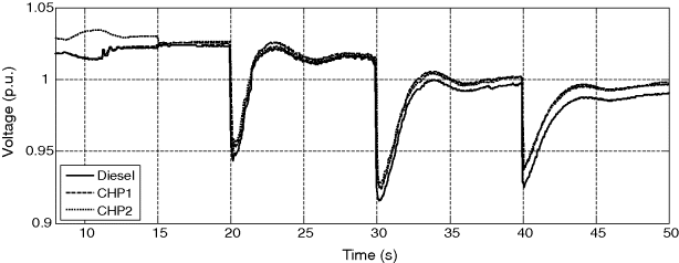
Considering the studied test network, the diesel and CHP units can restart successfully without network support. It can even be assumed that these units are already running and feeding their own loads in the first stages of the black start procedure. The diesel group was selected to energize the initial part of the MV network in order to create paths to connect the CHP units. Later, the islands formed by both CHP1 and CHP2 units are synchronized with the MV network and the MV/LV distribution transformers of Feeder A1 are energized. In order to prevent large inrush currents and therefore voltage drops inside the energized multi-microgrid system, this task should be performed in stages. Thus, three groups of transformers were considered and energized at different times. The impact of these control actions on the MV network can be observed in Figures 5.17 and 5.18. The adopted procedure allows the system frequency and bus voltages to be kept within acceptable limits.
Figure 5.17 Frequency following islands synchronization and feeder A1 energization
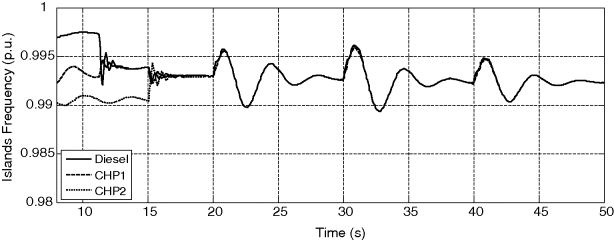
Figure 5.18 Bus voltages following islands synchronization and feeder A1 energization
When the multi-microgrid network is fully energized, and all CHP units are synchronized with the MV network, the service restoration proceeds with load supply and integration of other DG units. Load is restored step by step according to the integrated generation capacity. As the secondary frequency control is disabled, every load pick-up results in a system frequency drop. Therefore, it is necessary to connect further DG units as the amount of restored load increases. For this purpose, when the CAMC observes system frequency higher than its nominal value, power is available to connect additional load and therefore, depending on the system capacity, the CAMC determines the amount of additional load to be connected. After supplying all the loads, the secondary frequency control is activated and the system nominal frequency is restored. The feasibility of these control actions is illustrated in Figures 5.19 and 5.20.
Figure 5.19 Frequency variation during load supply and generation increasing stage
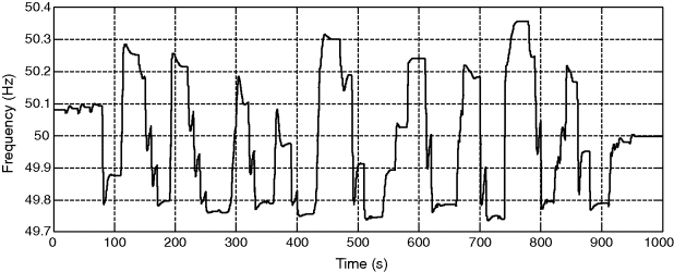
Figure 5.20 Voltage variation during load supply and generation increasing stage
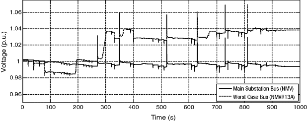
The results obtained demonstrate the technical feasibility of the multi-microgrid concept improving service restoration procedures on distribution systems allowing the reduction of load restoration times. Islanded operation of parts of the MV grid during the restoration sequence has a key role in the success of this procedure. In addition, multi-microgrid service restoration can be considered as a great opportunity to take advantage of generation systems, traditionally considered as non-controllable, as support to the load supply. Based on the multi-microgrid hierarchical control system and exploiting its communication infrastructure, the entire multi-microgrid service restoration procedure can be fully automated.
5.6 Dynamic Equivalents
Large deployment of microgrids within the framework of the multi-microgrid concept presented previously will lead to very large MV systems comprising hundreds or even thousands of these active cells formed at the LV levels and connected to the MV network, together with other DG units. In order to operate the microgrid within the expected reliability levels, focusing specially on the multi-microgrid autonomous mode of operation, transient and dynamic stability studies need to be performed at the MV level. Thus, multi-microgrid islanding and load-following are key studies to be performed within this framework. However, using detailed mathematical models able to accurately represent the microgrid dynamic behavior with impact on the MV level means dealing with very high dimension systems, with a computational burden that will render multi-microgrid dynamic behavior studies unfeasible. Therefore, deriving dynamic equivalents for microgrids is required to speed up this type of numerical simulation.
The microgrid reduced-order models are intended to replace the microgrid detailed models according to the following guidelines:
- The microgrid dynamic equivalent should be an accurate representation of the corresponding detailed model, regarding the relevant dynamics with impact on the MV system.
- The cost of building the dynamic equivalent must be much smaller than the cost of performing the transient analysis using the microgrid detailed model.
- The obtained microgrid dynamic equivalents will be integrated in dynamic simulation tools.
Since the microgrid's main features do not lend themselves to the application of modal analysis and coherency based methods, system identification techniques can be exploited for deriving dynamic equivalents for microgrids. Since the equivalent model is developed in a system-oriented framework, a solid system definition is provided in Section 5.6.2, before starting the system identification procedure. Based on the available physical knowledge, effectively used, two suitable approaches are formulated, relying on using either a black box model structure or a physical model structure. The first tries to exploit the full response of the microgrid, while the second tries to understand the physical behavior of the different components of the microgrid.
5.6.1 Application of Dynamic Equivalence Based Approaches to Microgrids
Typical approaches to deriving dynamic equivalents for power systems rely basically on system reduction and system identification based techniques [20,21]. Reduction techniques are based on aggregation and elimination of some components of the system detailed model by exploiting modal analysis [22,23] and coherency based aggregation methods [24–26]. In the system identification based approaches, the dynamic equivalents are derived from data, using a dataset comprising either simulated data or measured data collected at specific points of the system. The parameters of the model are then adjusted, so that the model response matches the observed data. Artificial Neural Networks (ANNs) have been the most prevalent system identification based method, because of their high inherent ability in modeling nonlinear dynamic systems, being the dynamic properties obtained only from data [27–31].
When compared with conventional power systems, microgrid systems have no centralized synchronous machines. Rather, despite their lower physical dimensions, the microgrid comprises a number of small-scale DG units, with different technologies, connected to the LV network through power electronic interfaces and exhibiting nonlinear dynamic behavior. Also, different microgrids will have quite different compositions and obtaining detailed information about all of their components will be a very difficult task. Thus, the application of system reduction based approaches for deriving dynamic equivalents for microgrids have the following main drawbacks:
- Modal analysis requires performing very time-consuming procedures and the obtained reduced-order models lack accuracy when the system steady-state operating conditions move away from the base case.
- Coherency based methods are suitable only for conventional power systems with synchronous generators concentrated into a few areas. Moreover, the term coherency becomes less meaningful since power electronic based interfaces can almost completely separate the dynamic behavior of generators from the network, resulting in quite different dynamics of DG units, strongly influenced by the control systems of power electronic interfaces. Also, some DG technologies do not have rotating parts – for example, fuel cells and PV systems.
Due to its general applicability, system identification based approaches have been exploited for deriving aggregated models for distribution networks with large-scale integration of DG [30,31]. The ANN based approaches have been the key players in this endeavor, since they can learn nonlinear maps from data. This feature, together with the introduction of powerful optimization tools, allows the handling of a wide range of nonlinear dynamics, including the relevant dynamics of microgrids [32], lacking detailed physical knowledge. This represents a significant advantage, especially when there is a limited understanding of the relations between system variables.
5.6.2 The Microgrid System Definition
For the purposes of analysis, and to get a better perspective for setting up a reduced equivalent system, the detailed model of the whole multi-microgrid system is divided into two main parts [32–34]: (1) the internal area to be retained for detailed analysis and the external area to be replaced by the equivalent model, as depicted in Figure 5.21, (2) the dynamic system to be identified, consisting of a set of differential and algebraic equations describing the state evolution over time of the physical system – the microgrid.
Figure 5.21 multi-microgrid equivalent model including the microgrid dynamic equivalent
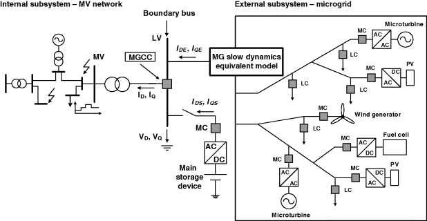
Detailed models of microgrids focus on the DG technologies, on their power electronic based interfaces and on the control strategies suitable for operating the inverter dominated microgrid. Power electronic converters are represented by their control functions only, implementing the VSI and PQ control, so that switching transients, harmonics and inverter losses are neglected [3,18,35–38]. Also, three-phase models have been used for both DG units and power electronic based interfaces, only considering microgrid three-phase balanced operation. It was also assumed that the microgrid is operating within the framework of a single master operation (SMO) control strategy [3]. By performing time domain simulations using the microgrid detailed models, two different time scales can be distinguished:
- VSI interfacing the microgrid main storage device, with fast dynamic responses and
- small-scale DG systems interfaced through PQ inverter controls, with slow dynamic responses.
Therefore, suitable dynamic equivalents for microgrids comprise two main parts:
- the microgrid main storage device, represented as a constant DC voltage source behind the VSI detailed model and
- the microgrid slow dynamics equivalent model representing the aggregation of all the remaining components.
Then the aim of the system identification procedure is to identify the equivalent model able to represent the microgrid slow dynamic behavior, as represented in Figure 5.21. Thus, based on the system definition and using the engineering expertise, the numerical set-up was implemented – a dedicated dynamic simulation platform able to design suitable numerical experiments with microgrids, in order to produce sufficiently informative datasets. Also, the simulation platform should be able to evaluate the performance of the microgrid reduced-order models at the final stage of the system identification procedure.
Then, the microgrid detailed model is excited through simulated disturbance scenarios into the MV network, such as multi-microgrid islanding and load-following when the multi-microgrid is operated autonomously, being the microgrid dynamics captured by means of both the input and output electrical signals measured at the system boundary according to a suitable sample time. Boundary bus voltages – expressed in the D-Q synchronous reference frame – and system angular frequency are considered as inputs, while the boundary bus injected currents in the tie lines, also expressed in the D-Q reference frame, are considered as outputs. Node elimination and aggregation is performed by making the injected currents of the aggregated model equal to the currents in the tie-lines. Thus, the microgrid slow dynamics equivalent model is disturbed by both boundary bus voltage and system frequency variations, reacting by varying the injected currents into the boundary bus, operating according to the principles of a Norton model [34].
5.6.3 Developing Micogrid Dynamic Equivalents
Developing reduced-order models, using system identification based procedures, requires the following main tasks to be performed:
- data generation,
- model structure selection,
- identification method selection,
- model validation.
However, nonlinear system identification based techniques are application dependent. General guidelines recommend using the available prior knowledge as well as the engineering expertise to derive models as close as possible to their intended purpose. Regarding the model structure selection, the physical insights about the microgrid dynamic behavior have been combined with the formal properties of the models, yielding two promising approaches:
- black-box modeling based on a time delay neural network (TDNN) model structure, aiming to exploit the full response of the microgrid when excited after a disturbance and
- physical modeling, seeking to understand the physical behavior of the different components of the microgrid.
5.6.3.1 TDNN Based Dynamic Equivalents
The TDNN based on the multi-layer perceptron (MLP) neural networks have high capability for dealing with complicated nonlinear problems. When well-trained, the TDNN can replace the microgrid's slow dynamics and it is expected that it will properly interact with the retained network for a wide range of operating conditions. In the following, we describe the main tasks to be performed within the framework of system identification based procedures using TDNN to develop microgrid dynamic equivalents.
Data Generation
The dataset is almost the only source of information for building the TDNN based dynamic equivalent model. Thus, a detailed model of the multi-microgrid is used for generating a sufficiently informative dataset, comprising a large number of samples, in order to form appropriate training and validation datasets. Thus, boundary bus voltages, system frequency and injected currents are stored in a database during the simulation of the disturbances, in order to build suitable training patterns. Since signals are likely to be measured in different physical units, it is recommended to remove the mean and scale all signals to the same variance, in order to avoid the tendency for the signal of largest magnitude to be too dominating. Moreover, scaling makes the training algorithm numerically robust and leads to a faster convergence, and also tends to give better models [39]. In order to generate a more robust TDNN, which is able to simulate the microgrid dynamic behavior under different operating conditions, normalized deviations of voltage, system frequency and currents from the corresponding steady state are used, similarly to the approach proposed in [30,31].
Thus, a function ![]() computes the normalized voltage (
computes the normalized voltage (![]() ,
, ![]() ) and system frequency deviations (
) and system frequency deviations (![]() ) while a function
) while a function ![]() computes the current to be injected into the retained network (
computes the current to be injected into the retained network (![]() ,
, ![]() ), as follows:
), as follows:
(5.14) ![]()
(5.15) ![]()
Where ![]() ,
, ![]() are the maximum deviations of the direct and quadrature components of the voltage,
are the maximum deviations of the direct and quadrature components of the voltage, ![]() ,
, ![]() are the maximum deviations of the direct and quadrature components of the injected current and
are the maximum deviations of the direct and quadrature components of the injected current and ![]() is the maximum deviation of the system frequency, regarding its nominal value,
is the maximum deviation of the system frequency, regarding its nominal value, ![]() . In turn,
. In turn, ![]() ,
, ![]() represent the steady-state voltage in the direct and quadrature components, and
represent the steady-state voltage in the direct and quadrature components, and ![]() ,
, ![]() represent the steady-state current in direct and quadrature components.
represent the steady-state current in direct and quadrature components.
The initial steady-state values of boundary bus voltage and injected current of the microgrid slow dynamics equivalent model are determined through the initial load flow calculations. Their maximum deviations, as well as the maximum frequency deviation, are obtained from the dynamic simulation of the largest amount of load connection and disconnection upon multi-microgrid islanding.
Model Structure Selection
TDNN represents the microgrid slow dynamics according to the external dynamics based approaches [39]. Then, the nonlinear model comprises the regression vector and nonlinear mapping that combines the regressors into a one-step-ahead prediction, as represented in Figure 5.22.
Figure 5.22 TDNN based microgrid slow dynamic equivalent model
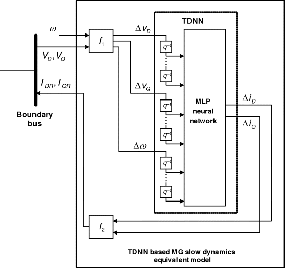
Therefore, selecting the TDNN model structure requires selecting a particular structure of the regression vector and subsequently to specify the number of hidden units, in an attempt to determine good network architectures for this choice of regressors. Taking into account the intended purpose of the microgrid dynamic equivalent, it should be noted that past system outputs are not available. Thus, the adopted structure of the regression vector is based on the nonlinear finite impulse response (NFIR) model, considering the following assumptions:
- The nonlinear dynamic model output was not considered, to avoid problems of error accumulation and error instability in time domain simulations.
- The model order results from a trade-off solution between the input space dimensionality and the number of time delays that allow representing the dynamics of interest.
The definition of the MLP structure comprises only the definition of the hidden units and the choice of the activation functions, being the number of regressors as well as the number of hidden units obtained further, within the framework of training and validation stages, by using trial and error approaches.
Estimation of the TDNN Adjustable Parameters
At this stage the MLP network is trained using the back-propagation method, with the Levenberg–Marquardt algorithm, in order to provide the best possible one step ahead prediction in the sense of the mean square error. Due to its simplicity, early stopping is also used in order to avoid overfitting, thus realizing the best bias/variance trade-off. Since we always want the trained neural network model to also be validated on a validation dataset not used to extract training patterns, the collected dataset is then split between the training and validation datasets. Some care needs to be taken in order to guarantee similar properties between the two datasets regarding the representation of the system properties. As several MLP neural networks with randomly initialized parameters are trained, the validation error is also used as the first criterion to reject poor models.
Model Validation
After the training procedure, the performance of the TDNN based equivalent models with less generalization error is evaluated in the dynamic simulation platform. A microgrid slow dynamics equivalent model is then embedded in the validation module forming the multi-microgrid equivalent model. The model performance is evaluated by comparing its response following perturbations that occur in the retained subsystem not used during the training phase with the response obtained using the microgrid detailed model. For this purpose, in addition to the TDNN itself, the auxiliary functions ![]() and
and ![]() are included in the dynamic simulation, interfacing the TDNN and the retained system according to Figure 5.22. Thus, at each time step, the microgrid slow dynamics equivalent model recognizes the operating status of the retained network through the boundary bus voltage and system frequency and injects the corresponding current into the retained subsystem.
are included in the dynamic simulation, interfacing the TDNN and the retained system according to Figure 5.22. Thus, at each time step, the microgrid slow dynamics equivalent model recognizes the operating status of the retained network through the boundary bus voltage and system frequency and injects the corresponding current into the retained subsystem.
5.6.3.2 Dynamic Equivalents Based on Physical Modeling
Using a physical modeling approach the available physical knowledge regarding the microgrid composition and microgrid slow dynamic behavior is explicitly incorporated within the model structure and, therefore, the requirements to build the dataset are less demanding. Thus, the system identification main stages are related to the model structure selection and to the identification method, as described next.
Model Structure Selection
The physical laws that approximate the microgrid slow dynamics under study are similar to those that govern the active power control in a diesel engine [33], reacting to the system frequency variations by changing the output power, as can be seen in Figure 5.23.
Figure 5.23 Model structure of the microgrid slow dynamics equivalent model

Since the microgrid slow dynamics reduced-order model is required to behave according to the principles of the Norton model, the instantaneous power theory [40] was used in order to determine the network injected current. For this purpose, only physical laws are used without parameterization, so that the parameters of the physical model structure whose values have to be estimated during the identification procedure are gathered into the parameter vector, ![]() , as
, as
(5.16) ![]()
The block of instantaneous power theory requires only the implementation of the algebraic equations needed for computing the current injected on the retained subsystem (![]() ,
, ![]() ), based on the boundary bus voltage (
), based on the boundary bus voltage (![]() ,
, ![]() ) and on the active power delivered by the microgrid slow dynamics equivalent model,
) and on the active power delivered by the microgrid slow dynamics equivalent model, ![]() . In addition, a given reactive power is used,
. In addition, a given reactive power is used, ![]() , corresponding either to a predefined value linked to the power factor of the DG units or to a reactive power setpoint sent by the MGCC, according to the SMO control strategy [3].
, corresponding either to a predefined value linked to the power factor of the DG units or to a reactive power setpoint sent by the MGCC, according to the SMO control strategy [3].
The Identification Method
In order to estimate the parameters of the physically parameterized model structure, a suitable identification method is required. For this purpose the EPSO tool [11,12] was adopted as a global optimization tool together with the sum square error (SSE) criterion [33,34]. In this context, the vector of parameters (![]() ) provides the particle phenotype descriptions corresponding to the particle positions into the predefined parameter space. The parameter estimation procedure is performed online. For each particle, the loss function expressed in terms of the SSE is evaluated by performing time domain simulations. Therefore, some interaction between the EPSO algorithm and the multi-microgrid equivalent model is required, as can be seen in Figure 5.24.
) provides the particle phenotype descriptions corresponding to the particle positions into the predefined parameter space. The parameter estimation procedure is performed online. For each particle, the loss function expressed in terms of the SSE is evaluated by performing time domain simulations. Therefore, some interaction between the EPSO algorithm and the multi-microgrid equivalent model is required, as can be seen in Figure 5.24.
Figure 5.24 Flowchart of the parameters estimation procedure in microgrid physical modeling
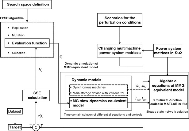
After defining the search space through both the minimum and maximum values of each parameter into the parameter vector, it is expected that the EPSO algorithm will perform the search to the global optimum or, at least, to a good local optimum in the SSE sense. For this purpose, after mutation has been performed by the EPSO algorithm, the following sequence of steps has to be carried out for each particle in the swarm:
Based on the SSE magnitude, the EPSO algorithm performs selection in order to build the swarm corresponding to the next generation. The above procedure is repeated, while the EPSO algorithm termination condition is not verified. Then, it is expected that the microgrid slow dynamics equivalent model thus obtained will present the best performance in time domain simulations, so that the validation procedure is embedded into the parameter estimation stage.
It should be mentioned that, for a fixed and known value of ![]() , fitting the current injected into the retained subsystem is similar to fitting the injected active power. Therefore, the dataset is created by the microgrid slow dynamics subsystem active power and the SSE is defined in this sense.
, fitting the current injected into the retained subsystem is similar to fitting the injected active power. Therefore, the dataset is created by the microgrid slow dynamics subsystem active power and the SSE is defined in this sense.
5.6.4 Main Results
The approaches presented in the previous sections are used to derive dynamic equivalents for microgrids using suitable test systems representing the multi-microgrid system. The microgrid slow dynamics equivalent models are connected to the system boundary bus in parallel with the microgrid main storage device, in order to replace the microgrid detailed model, thus forming the multi-microgrid equivalent model. The performance of the microgrid dynamic equivalents is evaluated by comparing the time domain responses of both the multi-microgrid detailed model and the multi-microgrid equivalent model, considering disturbances not used for extracting training patterns. Also, new initial steady-state operating conditions were considered, regarding the load and generation levels inside the microgrid and at the MV distribution network. Both microgrid dynamic equivalent models present a very high accuracy, with computational time savings, demonstrating the feasibility of the pursued system identification based approaches.
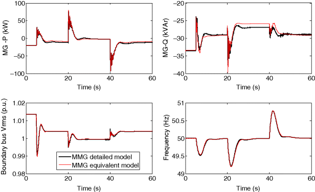
Regarding the TDNN based microgrid dynamic equivalent, the worst-case scenario was verified when the initial steady-state operating conditions moved from the base case by modifying the load inside the microgrid. For this scenario the sequence of actions was simulated as:
- multi-microgrid islanding at t = 5 s,
- connection and disconnection of an amount of load at t = 20 s and at t = 40 s, respectively.
The comparison between the TDNN based microgrid dynamic equivalent and the microgrid detailed model power responses can be seen in Figure 5.25. It can be concluded that this reduced-order model is effective in representing the dynamic behavior of the microgrid detailed model. Although the reactive power behavior presents a small loss of accuracy, this effect is quite small on the retained subsystem as can be observed from the boundary bus voltage and the system frequency behavior. The use of normalized deviations extends the TDNN capability of generalization to represent the microgrid dynamic behavior when the steady-state operating conditions move away from the base case. However, a very large computational effort is required to derive this reduced-order model and its domain of validity is restricted to the microgrid composition used for generating the dataset. Replacing the microgrid requires a new training procedure. These weaknesses have been overcome by using the microgrid physical model.
Figure 5.25 Performance of the TDNN based microgrid dynamic equivalent: behavior of microgrid active and reactive power, boundary bus voltage and system frequency
Then, a physical microgrid dynamic equivalent was derived using another test system comprising a microgrid with quite different composition and new steady-state operating conditions. The obtained reduced-order model of the microgrid was used to replace the microgrid in the same test system used in the case of TDNN based microgrid dynamic equivalents. In order to compare the performance of the two models, the same scenario of operation was used and the results obtained are presented in Figure 5.26, which shows that the models have similar performance.
Figure 5.26 Performance of the physical microgrid dynamic equivalent: behavior of microgrid active and reactive power, boundary bus voltage and system frequency
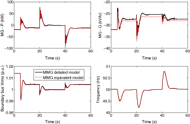
The response of the physical microgrid dynamic equivalent is in good agreement with that obtained using the multi-microgrid detailed model, demonstrating the effectiveness of the physical microgrid dynamic equivalent in representing the microgrid dynamic behavior, following multi-microgrid islanding and under load-following conditions upon multi-microgrid islanding. Using the available physical knowledge it was possible to select a proper model structure with physical representation, which can be easily integrated in dynamic simulation tools, being the domain of validity extended to represent the microgrid dynamic behavior with respect to the MV network with the required accuracy.
5.7 Conclusions
The definition of an effective control scheme for multi-microgrid operation is a key issue in order to accommodate efficiently microgeneration and MV-connected DG units. In particular, it is extremely important to specify the interactions among controllers, and namely the CAMC that plays a central role in this control architecture.
The control strategy to be adopted should then be based on a hierarchical scheme, ensuring both autonomy and redundancy. A communication strategy for multi-microgrid systems is also important and must be capable of allowing an exchange of information able to handle properly the dimension and complexity of the system. Furthermore, the control strategy must take into account the two possible operating modes in a multi-microgrid system: (a) Grid-connected and (b) Islanded mode.
The main functions to be included in the CAMC, housed at the HV/MV substation level, should be adapted and/or duplicated from the traditional DMS modules. The functions identified in this chapter were: Coordinated voltage var support, coordinated frequency support and emergency functions (black start). Advanced voltage control functionalities, as the ones described in this chapter, will enable large scale integration of DG and microgeneration without jeopardizing the grid operating conditions and optimizing its performance.
Regarding the multi-microgrid stability assessment, dynamic and transient studies are required focusing on the multi-microgrid islanded mode of operation. Multi-microgrid islanding and load-following will play key role in these studies. Since performing these studies using detailed modeling approaches will be not be practical, microgrid dynamic equivalents have been developed in order to speed up time domain simulations. For this purpose, system identification based techniques exploiting TDNN and physical modeling can be used. From the studies performed we can deduce that physical microgrid dynamic equivalents are well fitted for this purpose.
The main issues to be dealt with in the future are the deployment of smart metering infrastructure as a means of pushing forward the development of microgrids as an integrated part of the general smart grid concept. The costs of developing the microgrid and multi-microgrid concepts appear to be large and their economic feasibility needs to be carefully evaluated. However, if these concepts are integrated within a smart metering deployment, to be used to manage commercially the trade of electricity (either consumed or generated) it will become easier to get an early successful deployment. This requires that an advanced metering infrastructure should be conceived in order to accommodate the additional communication requirement that will allow the control and management of the microgrid.
In addition, future challenges should include tackling the issues resulting from massive integration of distributed storage devices. Distributed storage technologies can be based on mobile storage such as electric vehicles or on stationary storage, which includes fuel cells, regenerative fuel cells and lithium-ion batteries. The full deployment of the microgrid and multi-microgrid concepts requires the development of distributed storage technologies and the assessment of their impact concerning technical, economic and regulatory issues. Complementarily, a full assessment of active demand-side management strategies must also be carried out.
Developing the smart grid concept means increasing flexibility for generation, consumption and grid management. Microgrids are a way of bringing additional flexibility to the system dealing with these three components. Also very important is the need to define the rules for this flexibility, which can include contractual supply of this capability (centralized/bilateral, voluntary/mandatory). This means that appropriate regulation and adequate solutions need to be sought for and developed within this field.
1. European Project “Advanced Architectures and Control Concepts for More Microgrids – More Microgrids”, Project Reference no. 19864. Available at: http://www.smartgrids.eu/node/14.
2. Lopes, J.A.P.et al. (2003) “Management of Microgrids”, presented at the International Electric Equipment Conference, Bilbao, Spain.
3. Lopes, J.A.P., Moreira, C.L., and Madureira, A.G. (2006) Defining control strategies for microgrids islanded operation. IEEE T. Power Syst., 21, 916–924.
4. Madureira, A.G., Pereira, J.C., Gil, N.J.et al. (2011) Advanced control and management functionalities for multi-microgrids. Eur. T. Electr. Power, 21 (2), 1159–1177.
5. Resende, F.O., Gil, N.J., and Lopes, J.A.P. (2011) Service restoration on distribution systems using multi-microgrids. Eur. T. Electr. Power, 21 (2), 1327–1342.
6. Masters, C.L. (2002) Voltage rise – The big issue when connecting embedded generation to long 11kV overhead lines. Power Eng. J., 16 (1), 5–12.
7. Madureira, A.G. and Lopes, J.A.P. (2009) Coordinated voltage support in distribution networks with distributed generation and microgrids. IET Renewable Power Generation, 3 (4), 439–454.
8. Madureira, A. (2012) Coordinated Voltage Control in multi-microgrids, LAP Lambert Academic Publishing, Saarbrucken.
9. Schwefel, H.P. (1995) Evolution and Optimum Seeking, John Wiley & Sons, New York.
10. Kennedy, J. and Eberhart, R. (1995) “Particle swarm optimization”, in Proc. IEEE International Conference on Neural Networks, vol. 4, Perth, Australia, pp. 1942–1948.
11. Miranda, V. and Fonseca, N. (2002) “EPSO – Best-of-two-worlds meta-heuristic applied to power system problems”, in Proc. 2002 Congress on Evolutionary Computation, Honolulu, Hawaii, pp. 1080–1085.
12. Miranda, V. and Fonseca, N. (2002) “EPSO – Evolutionary Particle Swarm Optimization, a new algorithm with applications in power systems”, in Proc. 2002 Asia Pacific IEEE/PES Transmission and Distribution Conference and Exhibition 2002, vol. 2, Yokohama, Japan, pp. 745–750.
13. Ciric, R.M., Feltrin, A.P., and Ochoa, L.F. (2003) Power flow in four-wire distribution networks – General approach. IEEE T. Power Syst., 18 (4), 1283–1290.
14. Kundur, P. (1994) Power System Stability and Control, McGraw-Hill, New York.
15. Gil, N.J. and Lopes, J.A.P. (2007) “Hierarchical Frequency Control Scheme for Islanded Multi-Microgrids Operation”, in Proc. IEEE PES PowerTech 2007, Lausanne, Switzerland.
16. Gil, N.J. and Lopes, J.A.P. (2008) “Exploiting Automated Demand Response, Generation and Storage Capabilities for Hierarchical Frequency Control in Islanded multi-microgrids”, in Proc. 16th Power Systems Computation Conference, Glasgow, Scotland.
17. Microgrids Project Deliverable DD1 (2009), “Emergency strategies and algorithms”, J.A. Peças Lopes. Available at: http://microgrids.power.ece.ntua.gr/micro/micro200/deliverables/Deliverable_DD1.pdf.
18. Moreira, C.L., Resende, F.O., and Lopes, J.A.P. (2007) Using low voltage microgrids for service restoration. IEEE T. Power Syst., 22 (1), 395–403.
19. Lopes, J.A.P., Moreira, C.L., and Resende, F.O. (2005) “Microgrids black-start and islanding operation”, in Proc. 15th Power Systems Computation Conference, Liège, Belgium.
20. Milano, F. and Srivastava, K. (2009) Dynamic REI equivalents for short circuit and transient stability analyses. Electr. Pow. Syst. Res., 79 (6), 878–887.
21. Ramirez, J.M., Hernández, B.V., and Correa, R.E. (2012) Dynamic equivalence by an optimal strategy. Electr. Pow. Syst. Res., 84 (1), 58–64.
22. Undrill, J. and Turner, A. (1971) Construction of power system electromechanical equivalents by modal analysis. IEEE T. Power Ap. Syst., PAS-90 (5), 2049–2059.
23. Marinescu, B., Mallem, B., and Rouco, L. (2010) Large-scale power system dynamic equivalents based on standard and border synchrony. IEEE T. Power Syst., 25 (4), 1873–1882.
24. Miah, A.M. (2011) Study of a coherency-based simple dynamic equivalent for transient stability assessment. IET Generation, Transmission & Distribution, 5 (4), 405–416.
25. Podmore, R. and Germond, A. (April 1977) “Development of dynamic equivalents for transient stability studies”, Systems Control, Inc. Technical Report.
26. Pires de Souza, E.J.S. (2008) Identification of coherent generators considering the electrical proximity for drastic dynamic equivalents. Electr. Pow. Syst. Res., 78 (7), 1169–1174.
27. De Tuglie, E., Guida, L., Torelli, F.et al. (2004) “Identification of dynamic voltage-current power system equivalents through artificial neural networks”, in Proc. Bulk Power System Dynamics and Control – VI, Cortina d'Ampezzo, Italy.
28. Stankovic, A.M. and Saric, A.T (2003) “An integrative approach to transient power system analysis with standard and ANN-based dynamic models”, in Proc. 2003 IEEE Bologna PowerTech Conference, Bologna, Italy.
29. Shakouri, G.H. and Hamid, R.R. (2009) Identification of a continuous time nonlinear state space model for the external power system dynamic equivalent by neural networks. Int. J. Elec. Power, 31 (7–8), 334–344.
30. Azmy, A.M., Erlich, I., and Sowa, P. (2004) Artificial neural network-based dynamic equivalents for distribution systems containing active sources. Proc. IEE Proceedings – Generation. Transmission and Distribution, 151 (6), 681–688.
31. Azmy, A.M. and Erlich, I. (2004) “Identification of Dynamic Equivalents for Distribution Power Networks using Recurrent ANNs”, in Proc. IEEE PES Power Systems Conference and Exposition, vol. 1, New York City, USA, pp. 348–353.
32. Resende, F.O., Moreira, C.L., and Peças Lopes, J.A. (2006) “Identification of Dynamic Equivalents for Microgrids with High Penetration of Solar Energy using ANNs,” in Proc. 3rd European Conference of PV-Hybrid and Mini-Grid, Aix en Provence, France.
33. Resende, F.O. and Lopes, J.A.P. (2007) “Development of Dynamic Equivalents for Microgrids using System Identification Theory”, in Proc. 2007 IEEE Power Tech, Lausanne, Switzerland, pp. 1033–1038.
34. Resende, F.O. (2007) “Contributions for Microgrids Dynamic Modelling and Operation”, PhD Thesis, Faculty of Engineering, Porto University, Porto.
35. Barsali, S., Ceraolo, M., Pelacchi, P., and Poli, D. (2002) “Control techniques of Dispersed Generators to improve the continuity of electricity supply”, in Proc. 2002 IEEE Power Engineering Society Winter Meeting, vol. 2, New York, USA, pp. 789–794.
36. Caldon, R., Rossetto, F., and Turri, R. (2003) “Analysis of dynamic performance of dispersed generation connected through inverter to distribution networks”, in Proc. 17th International Conference on Electricity Distribution – CIRED, Barcelona, Spain.
37. El-Sharkh, M.Y., Rahman, A., Alam, M.S.et al. (2004) Analysis of active and reactive power control of a stand-alone PEM fuel cell power plant. IEEE T. Power Syst., 19 (4), 2022–2028.
38. Katiraei, F., Iravani, M.R., and Lehn, P.W. (2005) Micro-grid autonomous operation during and subsequent to islanding process. IEEE T. Power Deliver., 20 (1), 248–257.
39. Nelles, O. (2001) Nonlinear system identification, in From Classical Approaches to Neural Networks and Fuzzy Models, Springer Inc., New York.
40. Akagi, H., Kanazawa, Y., and Nabae, A. (1984) Instantaneous reactive power compensators comprising switching devices without energy storage components. IEEE T. Ind. Appl., IA-20 (3), 625–630.
