
10
PUF‐Based Authentication and Key Exchange for Internet of Things
An Braeken
Abstract
Key agreement between two constrained IoT devices that have never met each other is an essential feature to provide in order to establish trust among its users. Physical Unclonable Functions (PUFs) on a device represent a low‐cost primitive exploiting the unique random patterns in the device allowing it to generate a unique response for a given challenge. These so‐called challenge‐response pairs (CRPs) are first shared with the verifier and later used in the authentication process. The advantage of a PUF at the IoT is that even when the key material is extracted, an attacker cannot take over the identity of the tampered device. However, in practical applications, the verifier, orchestrating the authentication among the two IoT nodes, represents a cluster node in the field, who might be vulnerable for corruption or attacks, leading to the leakage of the CRPs. Possessing a huge number of CRPs allows its usage in machine learning algorithms reveal the behaviour of the PUF.
Therefore, in this chapter we propose a very efficient method to provide authentication between two IoT devices using PUFs and a common trusted cluster node, where the CRPs are not stored in an explicit way. Even when the attacker is able to get access to the database, the stored information related to the CRPs will not be usable input for any type of learning algorithm. The proposed scheme uses only elliptic curve multiplications and additions, instead of the compute intensive pairing operations as an alternative scheme recently proposed in the literature.
10.1 Introduction
Authentication between two IoT devices that have never met before is a frequently occurring problem. For instance, consider the following healthcare situation of a patient in a hospital room [1]. Suppose the patient is wearing a bracelet for blood pressure. In case of measurements above a certain threshold, the alarm button in the room should send a signal to the nurses. The communication between the bracelet and alarm button over the Internet and on local networks needs to be secured to gain trust and acceptance and to avoid direct physical harm to the patient, even loss of life. Both the bracelet and the alarm button are not authenticated before, but should be able to generate in a very efficient way trusted security material with the help of a common trusted verifier node, acting as a gateway.
In 2001, Physical Unclonable Functions (PUFs) were introduced as an interesting cryptographic primitive [2] and can be seen as the hardware equivalent of a one‐way function. A silicon PUF is a physical entity embodied in a physical structure that is easy to fabricate but practically impossible to clone, duplicate or predict, even if the exact manufacturing process is produced again. Instead of using a private key that is linked to the device identity, the authentication of PUFs is based on the usage of so‐called challenge‐response pairs (CRPs). The electrical stimulus, called the challenge (C), is applied to the physical structure in order to react, called the response (R), in an unpredictable manner due to the complex interaction of the stimulus with the physical micro‐structure of the device, which is dependent on physical factors introduced during the manufacturing process in an unpredictable and uncloneable manner. PUFs have relatively low‐hardware overhead and are thus very interesting in an IoT context. In [3,4] a list is provided of process parameter variations potentially impacting the delay and leakage characteristics of Complementary Metal Oxide Semiconductor (CMOS)‐based digital circuits, which can be used as PUF.
PUFs on devices have already been applied for device identification and authentication, binding hardware to software platforms, secure key storage, keyless secure communication, etc. Figure 10.1 illustrates a straightforward usage of PUFs for device identification and authentication as the PUFs can be seen as the unique fingerprint of the device. A security protocol is called a PUF‐based protocol when at least one of the entities is able to construct PUF challenges and responses, which are used in the rest of the protocol.
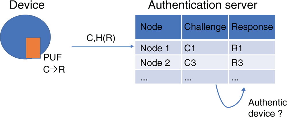
Figure 10.1 Example of PUF usage for device identification (C = Challenge, R = Response)
We assume for our construction the existence of a PUF mechanism in both devices willing to authenticate each other. Moreover, instead of the devices communicating directly with a common authentication server storing all CRPs of the devices, we also consider the existence of local cluster nodes, acting as verifier nodes for the two IoT devices in the field. The cluster nodes are responsible for requesting the required security information of the authentication server, where the security information does not include explicit CRP data which can potentially be abused later on in any kind of learning algorithm. We show that our proposed PUF‐based protocol is very efficient, compared to state‐of‐the‐art schemes presented in literature.
10.2 Related Work
Here, we focus the related work on the key agreement protocols in IoT as this is the part where PUFs are involved. For the secure communication phase, we can refer to the multiple identity‐based signcryption schemes [5,6] in the literature, which are cryptographic primitives performing both signature generation and encryption in one single phase.
Two main categories of key agreement schemes in IoT can be distinguished, these being key agreement from device to server and key agreement between two different devices. Note that we do not involve the discussion IoT devices have with user access, where two‐factor and three‐factor authentication is possible. We refer to the survey of [7] for these types of schemes and [8] for an anonymous symmetric key‐based key‐agreement protocol. The most important trends and schemes in each of these categories are now discussed.
10.2.1 Key Agreement from IoT Device to Server
For the first category of key agreement schemes, for simplicity, we assume that both device and server are registered with the same trusted third party (TTP). If not, the negotiation is further dealt with on the level of the TTPs. In the registration phase, there are two possible types of key material to be shared at the device side in order to guarantee that the identity of the device is linked with the claimed key material. The first type is through classical identity‐based public key cryptography. This can be arranged using different types of key establishment schemes, being the typical identity‐based schemes [9], certificateless [10], certificate‐based schemes [11] and proxy‐based schemes[12]. The identity‐based key establishment schemes require the usage of computationally intensive pairing operations and have inherent key escrow. Moreover, the schemes are vulnerable for a curious and honest TTP, which is a TTP that is honest in the sense that it performs all the required steps but curious in retrieving the data for own purposes (e.g., selling to third parties). Both the key escrow problem and the vulnerability for a curious and honest TTP can be avoided in the other two types of key establishment schemes since there, the resulting private key is generated by means of secret information coming both from the device and the TTP. The main difference between certificateless and certificate‐based schemes is that, in the first one, a secure channel is required for sharing the secret information of the device. Consequently, the certificate‐based key establishment schemes offer the most interesting features and the Elliptic Curve Qu‐VanStone (ECQV) [13] certificates mechanism is considered as the most efficient one as it is based on Elliptic Curve Cryptography (ECC). In the ECQV scheme, the public key of the user is generated by means of the identity of the user and the certificate generated by the TTP. As a consequence, instead of sharing the public key and identity of the user, it is sufficient to share the certificate and the identity of the user. Any other party, knowing the public key of the TTP, is then able to generate the public key of the user. Note that our proposed key agreement scheme is based on this principle. A key agreement mechanism based on the ECQV scheme has been proposed in [14]. In [14], Porambage et al. have proposed a key agreement protocol between sensor and server using the ECQV principle to be applied in the context of wireless sensor networks in distributed IoT applications.
The second type of key material, which can be used in these key agreement protocols, are the PUF‐based challenges and responses. The main advantage with PUF‐based key material is that the attacker cannot take over the identity of a tampered device, whose key material has been extracted. There exists multiple PUF‐based key agreement protocols for device to server in the literature. In [15], 21 server‐device/token key agreement protocols have been classified with respect to the features, device authenticity, server authenticity, device privacy, leakage resilience, number of authentications, resistance to noise, modelling resistance, denial of service (DoS) prevention, and scalability. It has been shown that only a very limited number are able to satisfy these features at a reasonable level. The main problems were vulnerability for DoS attacks, replay attacks, impersonation attacks, and synchronization problems. In the lightweight category of proposals are the Slender PUF, [16] noise bifurcation [17] and PUF‐lockdown protocol [18] retained, while in the non‐lightweight category only Reference protocol II‐A [15] and the protocol proposed by Sadegi et al. [19]. The main difference between these protocols [15–19] and our PUF‐based protocol is that these protocols take the noisiness of the PUF into account, while our protocol considers the usage of a strong and controlled PUF. Moreover, [16,17] also take countermeasures to offer resistance against machine‐learning attacks, although this cannot be completely excluded [15]. The proposed protocol in [18] prevents an attacker from querying a token for CRPs that has not yet been disclosed during a previous protocol run. The main weakness of [19] is that it does not scale well, as the server needs to exhaustively evaluate a pseudo‐random function for each registered token.
Another method for key agreement with the usage of PUFs is described in [20]. Here, the private key of the device is securely stored using a PUF construction. During the first communication message, the certificate issued by the manufacturer needs to be included. This approach is interesting, but strongly relies on the trustworthiness of the manufacturer, which is, in many cases, not verifiable by the device. In [21], the concept has been explained how PUFs, in combination with Blockchains, are able to establish authentication for IoT devices. Although the idea is promising, the impact of Blockchains on the performance of IoT devices is not fully clear for the moment.
10.2.2 Key Agreement between Two IoT Devices
For the key agreement between two IoT devices, e.g., in the case of sensor nodes in automobiles, smart home and smart cities, we assume that both devices are registered with the same TTP. During the key agreement process, the TTP can be involved or not. In the case where TTP is not involved, the most efficient identity‐based authentication and key agreement protocol proposed in literature can be found in [22], which only requires two phases and is also based on the ECQV key establishment protocol. We also mention in this context the standard key agreement scheme in IoT, called the Datagram Transport Layer Security (DTLS) protocol [23] with raw public keys, which has as the main difference, usage of less efficient certificates. In [24], the authors have replaced in the DTLS protocol these more compute intensive certificates by the ECQV certificates and evaluated the impact of this on the DTLS protocol.
However, without involvement of the TTP, a revoked device cannot be detected by the other party, without storage of a revocation list, which is very memory demanding and not advisable in a constrained IoT device. Therefore, it makes sense to also consider key agreement protocols with an active involvement of the TTP. Such protocol using classical public key cryptography mechanisms is evident, assuming that the TTP stores the list of valid identities and corresponding public keys of the participating IoT devices. Note that this scheme will be used as a benchmark to also compare the efficiency of our proposed scheme.
For the PUF‐based key agreement protocols between two IoT nodes with the aid of a common server (taking the role of TTP), who has stored the challenge‐response pairs of the PUFs from the different nodes, Chatterjee et al. recently proposed a protocol in [25]. The public keys of the devices are generated using the PUF results, followed by an identity‐based encryption mechanism for the actual secure communication. In [27], we show that their protocol is not resistant against man‐in‐the‐middle, impersonation, and replay attacks. In addition, we present an alternative PUF‐based protocol for the key agreement phase, which is even more efficient. In order to overcome the weakness of CRP leakage at the authentication server in case an attacker manages to get access to the database, Chatterjee et al propose in [26] a new version of the authentication protocol. In this chapter, we build further on the architectural model proposed in [26], but develop a slight modification of the scheme from [27] in order to also enable resistance against CRP leakage. Our proposed scheme is very efficient compared to [26], as we do not require compute‐intensive pairing operations.
10.3 Preliminaries
10.3.1 System Architecture
In [26], Chatterjee et al. introduced a cluster node in the field to perform the authentication between the two IoT devices, instead of the central authentication server supervising the different IoT nodes as in [25,27]. This is a more realistic scenario given the storage requirements of the authentication server. Therefore, we consider the similar architecture and protocol phases as in [26]. Consequently, the scheme consists of a registration phase, security association and authentication and key agreement phase. Note that we do not discuss the final secure communication phase, as this process is similar as in [27] and only relies on a signcryption scheme based on the ECQV scheme. Figure 10.2 depicts the system architecture and the different phases in the system.
- – In the registration phase, both IoT device and cluster node register with the authentication server, which is considered to be a TTP and fully trusted. This phase is assumed to be performed in a trusted and secure environment, e.g., by physical contact between the trusted authentication manager and the devices. For the IoT node, the identity
 and a set of challenges
  with corresponding hash of the responses
  are shared with the TTP. The cluster node shares its identity
  , public key
  and a common shared secret
  with the TTP. The corresponding secret key
  is securely stored in the cluster node.
 - – Upon request of the cluster node
 for authentication of a certain IoT node
  , the security association process is activated. Here, the Secure Association Provider (SAP) requests an entry of the TTP involving both
  , containing an implicit CRP, which is uniquely coded to become usable for
  in the authentication process and which is not leaking explicit information on the behavior of the PUF.
 - – In the authentication and key agreement phase, two nodes, registered to the same TTP and in the same communication range of a CN, are able to generate a private and public key pair. The public key of the one node is shared with the other with the help of the CN to guarantee the authenticity.

Figure 10.2 System architecture
10.3.2 Assumptions
Taking into account the described system architecture, we consider the following assumptions in the system.
- – The registration phase of both the IoT nodes and the CNs happens in a trusted and secure environment. The TTP is completely honest and stores the data with the highest security standards, being regularly audited by third parties. Consequently, no attacker is able to derive information at this stage or at the level of the TTP.
- – The communication between TTP, SAP, CN and IoT can run over insecure channels.
- – The CN possesses non‐volatile memory to store at least its private key
 and its common shared key
  with the TTP. No attacker is able to retrieve this information.
 - – The CN is considered to be honest but curious. In this scenario, the CN performs all the required actions, but might be interested in abusing some of the information in order to sell it to third parties.
- – The PUF designed in the IoT is inaccessible and cannot be predicted by the attacker as it is an implicit property of the device.
10.3.3 Attack Model
The attacker has two main goals. First, he can be interested in collecting CRPs of an IoT device in order to predict the behavior of the device by using it as input of a machine‐learning algorithm. This would allow impersonation of the IoT device at a later stage. The second goal of the attacker can be to directly impersonate a registered and legitimate IoT node without possessing the node and thus to derive a key with another unaware registered and legitimate IoT device. As the CN is considered to be honest but curious, the attacker can also corrupt the CN in order to derive information on either the CRPs or the key derived by the IoT nodes.
We consider the Dolev‐Yao attack model [29]. Here, the attacker is able to eavesdrop on the traffic, inject new messages, replay and change messages, or spoof other identities. Consequently, the attack is only limited by the constraints of the cryptographic methods used. We may assume that the attacker carries the message.
In practice, eavesdropping, intercepting and modifying data are activities that can be launched at any point where the traffic passes, from the IoT device to the authentication server. Some examples of how this can happen are as follows:
- –
In a local network:
- Anyone who is connected to the same Wi‐Fi is able to read the traffic.
- If the router (or some other part of the network) is hacked, the hacker can read and modify the traffic.
- The person that legitimately controls the network, e.g., the person responsible for the authentication of the server, can read and modify the traffic without even having to hack anything.
- –
Over the internet:
- The Internet Service Provider (ISP) is able to read and modify all the traffic, since it controls the hardware it passes through. The traffic can also go through other networks owned by unknown companies, eventually from different countries, and those who can also read and modify the traffic.
- When a nation state hands over to a court one of these companies passing the traffic, it can also read and modify the data (e.g., NSA).
10.3.4 Cryptographic Operations
First, we briefly explain the two most important building blocks to be used in the scheme. Next, some other required operations are also briefly mentioned.
10.3.4.1 PUFs
There are two types of PUFs, strong and weak. The difference is related to the number of responses that can be generated. A strong PUF is able to generate a large amount of challenge‐response pairs, while for a weak PUF, the number is limited, often to one.
The practical realisation of a strong PUF is challenging. PUFs also have problems for stabilizing the noise when generating the responses. In order to solve this issue, error correcting codes and assisting computed helper data are required. A good construction of both is essential to avoid leakage of information and resistance against fault and reliability attacks.
Recently, [28] proposes the construction of PUF‐FSM, a controlled strong PUF without the need for error correcting codes and helper data by only using the error‐free responses, which are fed in a finite state machine. In [26], a 5‐4 double arbiter PUF, consisting of five 64‐bit Arbiter PUF instances, together with a BCH encoder and decoder has been designed. Here, besides the challenge also helper data needed to be accompanied.
We do not focus on the design of a PUF in this paper, but assume the usage of such type of PUF‐FSM in our protocol. So, we are able to generate a large amount of challenges and responses in a controlled way. When using the PUF‐FSM, we can assume that the PUF evaluation behaves as a random oracle. Consequently, in our protocol, we do not integrate the helper data. In case a PUF requiring helper data like in [26] is used, the helper data should be dealt with in the same way as the challenge.
10.3.4.2 Public Key‐Related Operations
The public key‐related operations in our proposed scheme rely on ECC [30], offering more light‐weight public‐key cryptographic operations than the classical discrete logarithms or RSA‐based systems. For example, 1024‐bit RSA corresponds with a 160‐bit ECC scheme from a security point of view.
Let us denote the elliptic curve (EC) ![]() to be used in our scheme by
to be used in our scheme by ![]() with
with ![]() and
and ![]() two constants in
two constants in ![]() and
and ![]() . In [31,32], standardized curve parameters are described for p between 113 and 571 bits. The base‐point generator
. In [31,32], standardized curve parameters are described for p between 113 and 571 bits. The base‐point generator ![]() of
of ![]() is of prime order
is of prime order ![]() . All points on
. All points on ![]() , together with the infinite point form an additive group. There are two elementary operations related to ECC resulting in another point of the EC, the EC multiplication
, together with the infinite point form an additive group. There are two elementary operations related to ECC resulting in another point of the EC, the EC multiplication ![]() with
with ![]() and the EC addition
and the EC addition ![]() . ECC relies on two computational hard problems.
. ECC relies on two computational hard problems.
- – The Elliptic Curve Discrete Logarithm Problem (ECDLP). This problem states that given two EC points
 and
and  of
of  ), it is computationally difficult for any polynomial‐time bounded algorithm to determine a parameter
  , such that
  .
. - – The Elliptic Curve Diffie Hellman Problem (ECDHP). Given two EC points
 with two unknown parameters
  and
and  the base‐point generator of the defined EC, it is computationally difficult for any polynomial‐time bounded algorithm to determine the EC point
  .
.
10.3.4.3 Other Operations
Furthermore, we denote the operation ![]() as the one‐way cryptographic hash function (e.g., SHA2 or SHA3) that results in a number of
as the one‐way cryptographic hash function (e.g., SHA2 or SHA3) that results in a number of ![]() . As encryption algorithm AES or even a lightweight crypto algorithm can be used. The encryption of a message
. As encryption algorithm AES or even a lightweight crypto algorithm can be used. The encryption of a message ![]() with key
with key ![]() is denoted by
is denoted by ![]() and the corresponding decryption operation on the ciphertext
and the corresponding decryption operation on the ciphertext ![]() by
by ![]() . The concatenation of two messages
. The concatenation of two messages ![]() and
and ![]() is denoted by
is denoted by ![]() and the xoring of two messages by
and the xoring of two messages by ![]() .
.
We assume that these functions, the EC parameters together with the EC operations, are implemented in each entitiy participating the scheme. In addition, the IoT nodes possess a reliable and secure PUF.
10.4 Proposed System
We now discuss the different operations to be executed in each of the phases in more detail.
10.4.1 Registration Phase
For the IoT node, a number of random challenges (C) and corresponding responses (R) are generated by the IoT node. These pairs ![]() , together with the identity of the node, are sent to the TTP during the registration process of the IoT. The TTP is storing the pairs for each IoT node in a highly secure environment. Also the CN registers with the TTP by first deriving a common shared key
, together with the identity of the node, are sent to the TTP during the registration process of the IoT. The TTP is storing the pairs for each IoT node in a highly secure environment. Also the CN registers with the TTP by first deriving a common shared key ![]() with the TTP and by sending its identity
with the TTP and by sending its identity ![]() and public key
and public key ![]() . The tuple
. The tuple ![]() is also stored securely by the TTP.
is also stored securely by the TTP.
10.4.2 Security Association Phase
When an IoT node ![]() launches a key establishment request with another IoT node
launches a key establishment request with another IoT node ![]() on timestamp
on timestamp ![]() , both in the same communication range of CN, the CN forwards the request
, both in the same communication range of CN, the CN forwards the request ![]() to the SAP. The SAP in turn queries the TTP for two valid entries to be used in the authentication and key agreement phase. As a result, the TTP first verifies if
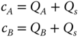
to the SAP. The SAP in turn queries the TTP for two valid entries to be used in the authentication and key agreement phase. As a result, the TTP first verifies if ![]() are registered. If so, it then derives four messages, using two CRPs of each node randomly selected from its database. Denote
are registered. If so, it then derives four messages, using two CRPs of each node randomly selected from its database. Denote ![]() , then the following key material is computed.
, then the following key material is computed.
Finally, the four tuples ![]() are sent by the TTP to the SAP and further forwarded to the CN.
are sent by the TTP to the SAP and further forwarded to the CN.
10.4.3 Authentication and Key Agreement Phase
Due to the symmetry of the protocol, it is suffice to explain the steps from the side of Node 1 after the second step. Figure 10.3 illustrates the complete overview of the different steps between Node 1 and the server. A similar parallel process is executed between server and Node 2.
- – To start the key agreement phase, Node 1 shares with the server the identities
 of Nodes 1 and 2 respectively, together with the current timestamp
  . Node 1 opens a new session in its memory and stores the three parameters
  in it.
 - – Upon arrival of the message, the CN forwards to the SAP the message
 . As explained before, the Security Association phase is launched and results in the four tuples
 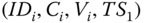 with
with  . Using its common shared key
  with the TTP, the CN is able to derive
 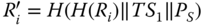 by decrypting
  .
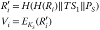
. - – Based on this information, the CN now computes both:

Also, a hash value to ensure the integrity and authentication of the server needs to be included. This value for Nodes 1 and 2 respectively is computed as follows:

The message
 is sent to Node 1 and
 is sent to Node 2. The server opens a new session in which the parameters
  are stored.
 - – Upon arrival of the message, Node 1 first checks if the message consists of three parameters of the expected length. If so, it opens the stored session and retrieves the corresponding parameters

 of that session. Then, Node 1 computes
  for
for  in order to find
  and to derive
  from the received
  . This allows verification of
  . If correct, Node 1 also derives
  and the corresponding
  . Next, Node 1 randomly chooses
  to compute
  . Then, it computes
  . The message
  is sent to the server and
  are additionally stored in the session. Similarly, Node 2 generates the message
  and the parameters
  are stored in a new session at Node 2.
 - – Upon arrival of messages consisting of two parameters of the expected length, the server first verifies
 for the identities involved in any of the open sessions stored at the server side, where the current timestamp is in a reasonable timeframe with the corresponding stored timestamp. The verification of
  ensures the integrity and authenticity of both nodes. If it is correct, it starts with the derivation of the certificates for both nodes. Therefore, it randomly chooses a variable
  and computes
  . Next, the two certificates of the nodes are computed as
  and
and  :
:
These certificates are used to compute the auxiliary information
 for Node 1 and Node 2 to compute their private and public key pair respectively. Recall, that
  is the private‐public key pair of the server, where
  has been initially already transmitted by the CN.
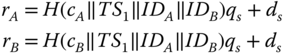
The corresponding public keys
 of the nodes 1 and 2 respectively are derived as follows:
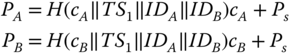
In addition, to guarantee the integrity of the communication, the values
 are also computed.
The values
 are sent to Node 1. In the same way, the values
 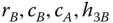 are sent to Node 2. The stored session is now closed at the server side.
 - – When a message of four parameters of expected length is received, Node 1 opens the stored session(s) where the current timestamp is in a reasonable timeframe with the stored timestamp. It starts with the computation of its private key
 . Its public key
  equals to
  , but also to
as derived by the CN. The private key is only known by the node itself as the random number
, but also to
as derived by the CN. The private key is only known by the node itself as the random number
 derived in the previous step is required. Using
  , Node 1 is able to compute the public key
  of Node 2. Note that this mechanism is based on the ECQV Implicit Certificate Scheme [13]. Finally, Node 1 checks the hash value
  . If OK, both nodes close the stored session and open a new session storing its private and public key pair together with the public key and identity of the other node.

Figure 10.3 Proposed key agreement scheme.
10.5 Security Evaluation
We now discuss the security features, established in the proposed scheme. The focus is on the key agreement scheme, as the registration phase is assumed to be performed in a completely trusted and secure environment.
- – Integrity. Integrity is obtained in every step of the protocol since every message contains a hash, which includes the other parts (or derivations of it) of the message.
- – Authentication of the Node. The nodes are authenticated if the check on the values
 are correct. These hash values contain the responses on the challenges, which can only be generated by the node possessing the PUF.
 - – Authentication of the Server. The server is authenticated by the node in both received messages. In the first received message by Node 1, the value
 , computed by the server, includes
  , while this value is not part of the received message. Instead,
  is masked by a hash value, which includes information on the response on the first challenge. Consequently, as only the CN is aware of the information of the response, Node 1 is ensured that the CN has sent the message. Moreover, the validity of the public key of the CN is also checked as it is included in the value
  , containing the information of the response and generated by the TTP. If the computation of
  by Node 1 and Node 2 respectively is similar to the stored value with the CN, the nodes are sure that the transmitted public key corresponds to the authentic one validated by the TTP.
In the second received message, the hash value
 is included. This hash value contains the responses on the two challenges, which is only known by the server. In addition, by adding the public keys of the two nodes into the hash, it also allows the nodes to verify the success of the process. Due to the symmetry of the protocol, the same reasoning holds for Node 2.
 - – Resistance against man‐in‐the‐middle attacks. As the authenticity of the sender is verified by the receiver in each step of the protocol, resistance against man‐in‐the middle attacks is guaranteed.
- – Resistance against impersonation attacks. Even if Node 1 is malicious, it is not possible for the node to derive information on the challenge‐response pairs of the other node from the messages exchanged between the CN and Node 2. This follows on from the fact that only hash values on the responses are included in the messages, which do not leak any information.
Also the CN cannot be impersonated as both keys
 are required to successfully perform the process. These keys are stored in the tamper‐resistant part of the memory. The key
  is necessary to derive the information of the CRPs. The key
  is required to construct the private and public key pair of each node. Moreover, the public key
  cannot be repudiated or changed as it is also embedded in the responses computed by the TTP during the security association phase. If
  were not used, the node cannot verify the authentication of that particular CN as it could also be another registered CN.
 - – Resistance against replay attacks. Replay attacks are avoided, due to the usage of the timestamp
 , which is included in all the hashes of the different transmitted messages and in the information of the responses on the selected challenges.
 - – Protection against denial of service attacks. Besides the first message, both the nodes and server can check at each step of the key agreement scheme the integrity and authentication by verifying the hash included in the messages. Consequently, in case a huge amount of false messages flow over the network, it will be very quickly discovered by each entity. Note that this feature is not present in [26] as in their scheme only in the last step is the IoT able to verify the validity. Consequently, in [26] an attacker can create a large amount of open sessions at each entity, where it is impossible to filter out the legitimate messages without finalizing the complete process.
10.6 Performance
Both the computational and communication costs are considered. We compare the efficiency of our solution with [26] and [27], as these are the only secure PUF‐based protocols in the literature with comparable architecture, i.e., deriving a common secret key between two IoT devices. Note that [26] has the additional advantage that no information on CRPs is leaked, compared to [27], and thus [26] offers the same security features as our proposed scheme.
For the key agreement scheme, which is based on the existence of PUFs, we utilize a straightforward public key variant as a benchmark, taking into account a similar architecture as this scheme and [26]. The different steps to be performed in the benchmark scheme are presented in Figure 10.4. In this scheme, we assume that the TTP stores the identity and public key of each of the registered IoT devices, instead of the CRPs. The IoT devices possess the public key ![]() of the TTP. Denote the private‐public key pairs of Node 1, Node 2, and CN by
of the TTP. Denote the private‐public key pairs of Node 1, Node 2, and CN by ![]() and
and ![]() respectively. The signature operation on a message
respectively. The signature operation on a message ![]() with private key
with private key ![]() is denoted by
is denoted by ![]() , while the verification of the signature
, while the verification of the signature ![]() with public key
with public key ![]() is denoted by
is denoted by ![]() . We assume the application of the Schnorr signature scheme for the complexity analysis of the next paragraph.
. We assume the application of the Schnorr signature scheme for the complexity analysis of the next paragraph.

Figure 10.4 Key agreement scheme based on public key cryptography used as benchmark
10.6.1 Computational Cost
We only focus on the most compute intensive operations, being pairings (P), HashToPoint operations (HP), EC multiplications (EM), EC additions (EA), symmetric key encryptions/decryptions (S) and hashes (H). We did not include the performance of the PUF operation as this is highly dependent on the underlying system. We note that in our scheme and [27], two PUF evaluations are used in order to validate the authentication of the request after each step. In [26], only one PUF evaluation is included, having the disadvantage that the authentication of the request can only be verified at the very end of the scheme. Without loss of security (besides intermediate authentication validation), we can easily remove the parameters ![]() , also resulting in one PUF evaluation at the IoT node. However, as we believe that this additional check is an added value of the scheme, we will not use this adaptation in the discussion of the performance.
, also resulting in one PUF evaluation at the IoT node. However, as we believe that this additional check is an added value of the scheme, we will not use this adaptation in the discussion of the performance.
Tables 10.1 and 10.2 compare the number of operations and the corresponding resulting time between our scheme and the ones of [26,27] and the benchmark scheme (BM) for the key agreement scheme in the IoT node and CN respectively, excluding the PUF evaluations. For the computation of the timings of both protocols, we have considered the numbers derived in [33], where all the operations have been evaluated on a personal computer with an Intel I5‐3210M 2.5 GHz CPU and Windows 7 operating system. The cryptographic operations have been implemented using the MIRACL cryptographic library. We have also assumed that there is only one stored session at the nodes and server side, similar to that in [26].
Table 10.1 Comparison of computational cost in key agreement phase for IoT device
| Operation | This | [26] | [27] | BM |
| P | 0 | 1 | 0 | 0 |
| HP | 0 | 1 | 0 | 0 |
| EM | 3 | 2 | 3 | 2 |
| EA | 1 | 2 | 1 | 0 |
| S | 0 | 0 | 0 | 2 |
| H | 10 | 6 | 10 | 2 |
| Total ( |
2.97 | 33.28 | 2.97 | 1.98 |
As can be concluded from the table, our proposed protocol is considerably faster from the node and the server side, compared to [26]. The main difference between our scheme and [26] is that we do not need to compute the intense hash‐to‐point and pairing operations. With respect to [27], the performance at the node side is approximately similar, but there is a small degradation in time at the server side. With respect to the public key‐based benchmark scheme, we can conclude that the difference in timing at the node side is acceptable, and there is even a small win for the timing at the server side. This is the price to pay for being resistant against hacking.
10.6.2 Communication Cost
For the determination of the communication cost, we take into account that the nodes' identity and the timestamp correspond to 32 bits. The challenges are represented by 64 bits and the responses by 48 bits, as in [26]. An EC with ![]() bits is used, which is also the length of the result of the hash value. As a consequence, the resulting sizes of the transmitted messages by both the node and the server in the key agreement protocol are enumerated in Table 10.3.
bits is used, which is also the length of the result of the hash value. As a consequence, the resulting sizes of the transmitted messages by both the node and the server in the key agreement protocol are enumerated in Table 10.3.
Table 10.2 Comparison of computational cost in key agreement phase for CN
| Operation | This | [26] | [27] | BM |
| P | 0 | 2 | 0 | 0 |
| HP | 0 | 2 | 0 | 0 |
| EM | 3 | 6 | 1 | 4 |
| EA | 4 | 10 | 2 | 1 |
| S | 0 | 0 | 0 | 1 |
| H | 10 | 6 | 10 | 2 |
| Total ( |
2.98 | 68.55 | 1.00 | 3.95 |
Table 10.3 Comparison of computational cost in communication phase (Node 1 is the sending node and Node 2 the receiving node)
| Entity | This | [26] | [27] | BM |
| Node 1 | 416 | 704 | 416 | 224 |
| Server | 1280 | 1152 | 1120 | 704 |
It can be concluded that the communication cost from the IoT node is slightly worse than the benchmark algorithm and equal to the system of [27]. It is almost twice as efficient compared to [26]. From the server side, again the benchmark algorithm outperforms all other schemes. Here, our scheme is the least optimal. However, if we remove one PUF evaluation, as discussed before, we are able to reach the same efficiency as [26]. Our scheme and the ones of [26,27] have the same structure and thus the same number of exchanged messages, being four between Node 1 and Server and three between Node 2 and server. These numbers are one lower in case of the benchmark key agreement scheme.
10.7 Conclusions
We have presented in this chapter a highly efficient authentication algorithm for two IoT devices containing a PUF implementation. The main advantage of including a PUF mechanism is that the security of the devices is guaranteed even if they become compromised as there are no secret keys stored. An interesting feature of our system is that neither the attacker eavesdropping the channel, nor the SAP or CN, is able to learn more about the structure of the CRPs in order to collect pairs for building a learning algorithm to reveal the behavior of the PUF.
We have compared the efficiency of the scheme with a straightforward public key‐based mechanism and could conclude that the performance difference between both is small. We have also shown that the scheme outperforms similar systems in literature.
References
- 1 Kumar, T.; Braeken, A.; Liyanage, M.; Ylianttila, M. (2017). May. Identity privacy preserving biometric based authentication scheme for Naked healthcare environment. 2017 IEEE International Conference on Communications (ICC), Paris, France (21–25 May 2017). IEEE.
- 2 Pappu, S.R. (2001). Physical One‐Way Functions. Ph.D. Thesis. Massachusetts Institute of Technology.
- 3 Blaauw, D., Chopra, K. Srivastava, A. and Scheffer, L. (2008). Statistical timing analysis: From basic principles to state of the art. IEEE Transactions Computer Aided Design Integrated Circuits Systems 27 (4): 589–607.
- 4 Abu‐Rahma, M.H. and Anis, M. (2007). Variability in VLSI circuits: Sources and digns considerations. Proc. IEEE International Symposium Circuits Systems, Los Alamitos, USA (27–30 May 2007). IEEE.
- 5 Zheng, Y. (1997). Digital Signcryption or How to Achieve Cost (Signature & Encryption) < Cost (Signature) Cost (Encryption). Annual International Cryptology Conference, Berlin, Germany (17–21 August 1997). Springer.
- 6 Braeken, A., Shabisha, P., Touhafi, A. and Steenhaut, K. Pairing free and implicit certificate based signcryption scheme with proxy re‐encryption for secure cloud data storage. CloudTech; IEEE, Rabat, Morocco (24–26 October 2016).
- 7 Tashi, J.J. (2014). Comparative analysis of smart card authentication schemes. IOSR Journal of Computer Engineering ( 16): 91–97.
- 8 Braeken, A. (2015). Efficient anonymous smart card‐based authentication scheme for multi‐server architecture. International Journal of Smart Homes 9: 177–184.
- 9 Shamir, A. (1984). Identity‐Based Cryptosystems and Signature Schemes. Workshop on the Theory and Application of Cryptographic Techniques, Paris, France (9–11 April 1984). Springer.
- 10 Al‐Riyami, S.S. and Paterson, K.G. (2003). Certificateless Public Key Cryptography. International Conference on the Theory and Application of Cryptology and Information Security, Taipei, Taiwan (30 November–4 December 2003). Springer.
- 11 Gentry, C. (2003). Certificate‐Based Encryption and the Certificate Revocation Problem. International Conference on the Theory and Applications of Cryptographic Techniques, Warsaw, Poland (4–8 May 2003). Springer.
- 12 Braeken, A., Liyanage, M. and Jurcut, A.D. (2019). Anonymous Lightweight Proxy Based Key Agreement for IoT (ALPKA). Wireless Personal Communications, pp.1–20.
- 13 Certicom Research. (2013). SEC4: Elliptic Curve Qu‐Vanstone Implicit Certificate Scheme, Standards for Efficient Cryptography Group. Version 1.0. http://secg.org/sec4-1.0.pdf (accessed 25 June 2019).
- 14 Porambage, P., Schmitt, C., Kumar, P. et al. (2014). Two‐phase Authentication Protocol for Wireless Sensor Networks in Distributed IoT Applications. Proceedings of the 2014 IEEE Wireless Communications and Networking Conference (WCNC), Istanbul, Turkey (6–9 April 2014) IEEE.
- 15 Delvaux, J. (2017). Security Analysis of PUF‐Based Key Generation and Entity Authentication. Ph.D. Thesis, Katholieke Universiteit Leuven.
- 16 Rostami, M., Majzoobi, M., Koushanfar, F. et al. (2014). Robust and reverse‐engineering resilient PUF authentication and key‐exchange by substring matching. IEEE Transactions Emerging Topics in Computing 2 (1): 37–49.
- 17 Yu, M.D. Verbauwhede, I. Devadas, S. and M'Raihi, D. (2014). A noise bi‐furcation architecture for linear additive physical functions. Proceedings of the 2014 IEEE International Symposium on Hardware‐Oriented Security and Trust (HOST), Arlington, USA (6–7 May 2014). IEEE.
- 18 Yu, M.D., Hiller, M., Delvaux, J. et al. (2016). A lockdown technique to prevent machine learning on PUFs for lightweight authentication. IEEE Transactions Multiscale Computer Systems 2: 146–59.
- 19 Sadeghi, A.R., Visconti, I. and Wachsmann, C. (2010). Enhancing RFID security and privacy by physically unclonable functions. In: Towards Hardware Intrinsic Security –Foundations and Practice (eds. A.R Sadeghi and D. Naccache), 281–305. Berlin, Germany: Springer.
- 20 Tuyls, P. and Batina, L. (2006). RFID‐Tags for Anti‐counterfeiting. Topics in Cryptology|CT‐RSA 2006, San Jose, USA (13–17 February 2005). Springer.
- 21 Guartime and Intrinsic ID. (2017). Internet of Things Authentication: A Blockchain solution using SRAM Physical Unclonable Functions. https://www.intrinsic-id.com/wp-content/uploads/2017/05/gt_KSI-PUF-web-1611.pdf (accessed 25 June 2019).
- 22 Simplicio, M.A., Jr., Silva, M.V., Alves, R.C. and Shibata, T.K. (2017). Lightweight and escrow‐less authenticated key agreement for the internet of things. Computer Communications 98: 43–51.
- 23 Wouters, P., Tschofenig, H., Gilmore, J. et al. (2014). T. RFC 7250|Using Raw Public Keys in Transport Layer Security (TLS) and Datagram Transport Layer Security (DTLS), June 2014. https://www.rfc-editor.org/rfc/rfc7250.txt (accessed 25 June 2019).
- 24 Ha, D.A., Nguyen, K.T. and Zao, J.K. (2016). Efficient authentication of resource‐constrained IoT devices based on ECQV implicit certificates and datagram transport layer security protocol. Proceedings of the Seventh Symposium on Information and Communication Technology, Ho Chi Minh City, Vietnam (8–9 December 2016).
- 25 Chatterjee, U., Chakraborty, R.S. and Mukhopadhyay, D. (2017). A PUF‐Based Secure Communication Protocol for IoT. ACM Transactions on Embedded Computing Systems 16: 67.
- 26 Chatterjee, U., Govindan, V., Sadhukhan, R. et al. (2018). Building PUF based Authentication and Key Exchange Protocol for IoT without Explicit CRPs in Verifier Database. IEEE Transactions on Dependable and Secure Computing (TDSC) 99: 1–1.
- 27 Braeken, A. (2018). PUF Based Authentication Protocol for IoT. Symmetry 10 (8): 352.
- 28 Gao, Y., Ma, H., Al‐Sarawi, S.F. et al. (2017). PUF‐FSM: A Controlled Strong PUF. IEEE Transactions on Computer‐Aided Design of Integrated Circuits Systems 30 (5): 99.
- 29 Dolev, D. and Yao, A. (1983) On the security of public key protocols. IEEE Transactions on Information Theory 29: 198–208.
- 30 Hankerson, D., Menezes, A.J. and Vanstone, S. (2003). Guide to Elliptic Curve Cryptography. New York, NY: Springer.
- 31 SEC 2: Recommended Elliptic Curve Domain Parameters, Certicom Research, Standards for Efficient Cryptography Version 1.0, September 2000. http://secg.org/sec2-v2.pdf (accessed 25 June 2019).
- 32 Recommended Elliptic Curves for Federal Government Use, National Institute of Standards and Technology, August 1999. http://csrc.nist.gov/groups/ST/toolkit/documents/dss/NISTReCur.pdf (accessed 20 November 2018).
- 33 He, D., Zeadally, S., Wang, H. and Liu, Q. (2017). Lightweight Data Aggregation Scheme against Internal Attackers in Smart Grid Using Elliptic Curve Cryptography. Wireless Communications and Mobile Computing 2017: 1–11. doi:10.1155/2017/3194845.