
11
Hardware‐Based Encryption via Generalized Synchronization of Complex Networks
Lars Keuninckx and Guy Van der Sande
Abstract
We present an encryption and authentication scheme suitable for ASIC or FPGA hardware implementation, which is based on the generalized synchronization of systems showing chaotic dynamical behavior. The scheme consists of a single‐driver system, which provides two identical driven systems with a complex waveform. The driven and driving systems synchronize with correlation no higher than
. A bit‐stream derived from their outputs is then used as an encryption or authentication key. The security of the scheme is based on the fact that it is easy to generate the response of the complex systems, given an input, but hard to do a system identification. Furthermore, the spectrum of the signals of the driver and driven system reveals no information. We show that regardless of their initial state, the distant receivers synchronize within a short time, relative to their internal timescale. We validate the bit‐streams generated by the driver using the NIST test suite for randomness and have found no deviations. Finally, we provide pointers as to the practical implementation and application of the presented scheme.
11.1 Introduction
Although the Internet of Things (IoT) promises to bring enormous benefits, the risks associated with it cannot be ingnored or underestimated. Take for example, the security risks associated when hackers are able to read a home's thermostat settings, identifying exactly if the occupants are at home or not. Or possibly disastrous: a hacker having access to the braking system of a (self‐driving) car. The potential risks associated with wireless enabled pacemakers and other implantable medical devices do not even need to be explained. While offering the huge benefit of remote diagnostics, at the same time, malignant access goes far beyond just a privacy breech and is potentially life‐threathening. Many current IoT devices have relatively weak security capabilities and are easy entry points for hackers. The reasons for this exacerbated cybersecurity risks are plenty. First of all, there is no real form of standardization, let alone a legal framework to adhere to, yet. Each device still speaks its own ‘language’, following its own custom protocols, making it very hard for the network to know which devices to really trust. Also, the cost of building extra security into these basic devices is often too high for commercial purposes. In an industrial context, a big increase in the number of sensors and devices that are being connected can be seen, creating a huge potential attack surface. Typically, such industrial IoT consists of decades‐old equipment and control systems that were never designed for exposure to the Internet and to its security risks. Together with an insufficient budget for implementing cybersecurity awareness, monitoring, and prevention technology, this leads to an ever‐growing number and type of attacks. Therefore, the future of successful deployment and acceptance of IoT‐enabled applications depends critically on the availability of fast, robust and low‐power encryption and authentication methods. Fast in this context equals low power by implementing short sleep/wakeup/sleep cycles. The encryption and authentication methods used should not require much real‐estate on the chip to be low cost. Hardware‐based methods will be preferred over software‐based to offload the main processor and provide encryption that is transparent at the application level.
In this Chapter, we will therefore propose a cost‐effective lightweight hardware‐entangled security solution for IoT systems. However, our proposed solution can also be employed in other security contexts. The development of new strategies to protect sensitive information from interception and eavesdropping has been receiving significant attention, also in our present‐day worldwide communication networks. Generally speaking, the aim of our work is the development and implementation of a novel random key distribution system based on the concept of generalized synchronization between distant elements in large networks. Such a random key synchronization system can have a significant impact in the field of physical layer‐based encryption techniques, offering not only high confidentiality but also potentially high‐speed real‐time encryption and decryption. Here, we put forward a scheme fit for a fully digitalized implementation.
Nowadays, confidentiality and the authenticity of information are mostly ensured through mathematical algorithms. Algorithmic key‐based encryption systems usually take a digital data stream and convolute it with a given binary pattern, which we refer to as the key. The resulting encrypted binary string can then be transmitted through a public communication channel. A classic example of this type of encryption is the Vernam cipher [1], where the recipient decodes the message using the same key‐string code as used for encryption. In this case, the key is agreed via another secure channel. This algorithm has been mathematically proven to be totally secure if the key is fully random, has the same length as the message and is used only once. This so‐called one‐time pad cryptography is, however, not suited for secure communications between two parties who have not been able to exchange encryption keys beforehand. To circumvent this drawback, other software cryptosystems relying on asymmetric‐key algorithms (public‐key cryptography such as RSA) have been developed. However, asymmetric algorithms use significant computational resources in comparison with their symmetric counterparts and therefore are not generally used to encrypt bulk data streams. Also, the effectiveness of these encryption techniques relies on the fact that it is computationally hard (but not impossible) to decrypt a message knowing only the public key. Therefore, the growing computational power and the fact that a key is used more than once remains a latent threat for current algorithmic cryptography. In order to strengthen the process of securely exchanging a private key other hardware‐oriented approaches have been proposed such as Physically Uncloneable Functions (PUFs).
PUFs have gained extensive research attention since they were first proposed in 2002 [2]. Their operational principle is based on inherent and unavoidable differences within every physical object that appear during the manufacturing process. This gives each physical instance a unique identity and, as such, could be used as a lightweight authentication scheme as well as anti‐counterfeiting solution. A first proposal was based on light scattering [2]. In Ref. [3], Gassend et al. proposed the first electrical PUF. They have gained a lot of attention as a secure key generation and storage mechanism. Their “unclonability” property is key: it should be impossible to build two physical instances of a PUF having exactly the same properties or characteristics.
PUFs are usually divided into two categories: weak PUFs and strong PUFs. A strong PUF can be queried with an exponential number of challenges to receive an exponential number of responses. They can be used in authentication protocols as well as for key generation and storage. Weak PUFs, on the other hand, only have a very limited challenge space and can only be used for key generation and storage.
PUFs suffer from some significant drawbacks. They are susceptible to environmental conditions and noise. Therefore, if a PUF is challenged twice by the same signal it can lead to two different and obviously unreliable responses. Also, existing electrical strong PUFs can be emulated in software. By relying on machine‐learning techniques, it is possible to approximate the required parameters sufficiently to have a software model which is in fact a very good clone of the real PUF. This is particularly true for the Arbiter PUF. Typically, some non‐linearity is added to make machine‐learning attacks more difficult. XOR PUFs are widely assumed to be secure against machine‐learning attacks if enough XORs are used [4–6]. Recently however, in Ref. [7] an attack method was demonstrated that scales favorably with the number of XORs.
While our approach resembles PUFs, the main idea originates from improving the confidentiality of an encrypted message by additional encoding at the physical layer using chaotic carriers. Chaos‐based encryption systems rely on two spatially separated chaotic systems to synchronize with each other. Once the two systems are synchronized, the chaotic output of the sender can be used as the carrier in which the message is hidden as a small modulation [8]. The receiver can extract the message by comparing the incoming signal with the synchronized one. Multi‐gigabit information transmission in real installed optical networks over several tens of kilometers have been demonstrated using this paradigm [9]. However, the necessity of sharing a chaotic carrier signal over a public channel reveals information on the specifics of the system used. Therefore, these chaos‐based communication systems offer confidentiality but cannot, for the moment, guarantee security. Such chaos‐based encryption schemes could augment the security by operating in a bidirectional fashion, whereby the modulating messages from both communicating parties involved disturbing the shared synchronization inducing signal. Since both parties have exact a priori knowledge of their own respective modulating signal, they are able to deduce the message imposed on the carrier by the other party [9,10]. However, an optimized hardware solution (compatible with software methods) for confidential data transmission is currently lacking and highly desired. Recently, we have demonstrated a system which can encrypt data in a new way, with a high level of security and which can be built using current off‐the‐shelf components [11]. This secure key distribution scheme was based on synchronized random bit generation and relied on the synchronization between a transmitter and a distant receiver through an uncorrelated chaotic driver signal. From the synchronized chaotic signals, a random key can be distilled that would be extremely difficult to reconstruct from the information shared in the public channel. This system does not suffer from the drawbacks of PUFs nor from the drawbacks of standard vanilla chaos encryption. In this chapter, we revisit this work and not only translate it to a fully digital implementation but also demonstrate a novel easy‐to‐implement lightweight random bit generator, that is based on a delay dynamical system.
In the next section, we introduce our general scheme and the chaotic driver, of which, the dynamical behavior is investigated in detail. Then, in Section 11.3, we show how the chaotic followers are built, giving pointers for further practical use. In Section 11.4 we show how the drivers and followers can be combined to form a complete encryption or authentication solution. Furthermore, we reason that a brute‐force attack on this system is futile. We wrap up our conclusions in Section 11.5, discussing ways in which this line of research may go further.
11.2 System Scheme: Synchronization without Correlation
In [11], we have presented an encryption‐scheme based on generalized synchronization of driven chaotic delay systems. Usually, the dynamical signals observed from systems that operate synchronously, by virtue of a (uni‐ or bi‐directional) coupling, exhibit some similarity. A simple example is found in identical pendulum clocks, which, when placed in each others, vicinity, from any given initial state tend toward swinging in unison after a while. This was first observed by the Christiaan Huygens in the 17th century [13]. Other examples include flashing fireflies, electrical oscillators and interpersonal brain activity as seen in mirror neurons [14]. Later, it was discovered that not only regular oscillators but also chaotic systems can synchronize, given the right circumstances [8]. Deterministic chaos is characterized as irregular motion that has a sensitive dependence on initial conditions: two identical chaotical systems brought into very close (yet unequal) initial states, will, after a while, show vastly diverging dynamics. The interested reader is refered to [15] for an excellent introduction to chaos theory. Generalized synchronization expands the common notion of synchronization to all causally related dynamics. An example of synchronization showing regular oscillatory dynamics is found in electronic oscillators that lock on a subharmonic of an injected signal. Inferring generalized synchronization from the observation of the system's dynamics is in general difficult and still an open problem [16]. This is especially true for driven chaotic systems and this is what is exploited in [11] to build an encryption system. Figure 11.1 shows the scheme of this system, which is also the basis of the scheme presented in this chapter. At the transmitter side, a chaotic driver generates a complex signal. This signal feeds into a chaotic follower or responder, which thus generates, in a deterministic way, its own output signal. Then, from the followers' signal a deterministic but by all accounts apparently random bitstream is derived. Naturally, this is only possible if the follower's dynamical behavior allows for this. This bitstream is then used as a one‐time‐pad key for encoding a binary plaintext, via an XOR‐operation. The probability of seeing a ‘1’‐bit in the ensuing encrypted message is:

since the bits of the message and the key are independent random variables. On the receiver side, the signal of the driver causes a second follower (identical to the one on the transmitter side) to generate the exact same signal. Thus, the bitstream derived from this second follower exactly equals the bitstream of the follower in the transmitter. The message is then recovered via an XOR‐operation of the receiver‐side bitstream and the cyphertext. Understandibly, a two‐way link can be built in the same way. A qualitative requirement for such a scheme to be succesful is that it is computationally hard to identify the relation between the driver signal and the key bitstream.

Figure 11.1 Encryption scheme based on generalized synchronization between two driven chaotic systems.
In [11] this scheme was demonstrated using an analog electronics approach, as shown in Figure 11.2a. The chaotic driver consisted of a series of nonlinear filter blocks (NLBs), Figure 11.2b, with a non‐monotonic response, Figure 11.2c, placed in a delay ring. Each responder used four similar nonlinear filters in a chain. The main purpose of that work was to illustrate how this scheme could be viable, yet there, as a final implementation, a fast photonic link was envisioned. It is instructional to explain why delay is used in the chaotic driver in Figure 11.2. First, in a photonic setting delay appears naturally by virtue of the finite propagation speed optical signals have when travelling along an optic fiber. It has long been known that delay can cause instabilities and even chaos in control systems. This is also the case for semiconductor lasers subjected to delayed feedback [17], thus offering a straightforward way to produce optical chaos. Therefore using delay in an electronic system mimics this feature. Second, and more importantly, what is special about delay dynamics is that they live in an infinite phase space. To determine how the state of a delay system evolves in time, one has to provide the initial condition of the delay line. This initial condition is defined by a function, having in theory an infinite number of points along the delay line. Then, at any further time, the state itself is a function of all values along the delay line. In contrast, the state of a finite‐order chaotic system (such as the archetypical Lorentz system) is fully defined by no more than the amount of numbers equalling the order of the differential equation that describes it. For the Lorentz system, the state is described at any time by only three numbers, hence its phase space is three‐dimensional. The consequence of having an infinite‐dimensional phase state is that delay‐based chaotic systems offer what is often loosely referred to as “richer” dynamical behavior, meaning they behave in a more erratic way. By using functionally the same nonlinear blocks in both the driver and responders, we were able to obtain similar spectral signatures in their signals. This is an important safeguard, since attackers are likely to investigate the spectral characteristics of the signals involved.

Figure 11.2 a) System diagram of the driver and responders or followers of [11]. Each nonlinear block (NLB) contains the subcircuit of Figure 11.2b. Pairwise NLB blocks in the responder chains were built using matched components. b) A single nonlinear block. The transistor circuit provides a non‐monotonic “bump‐like” function and is followed by a first‐order filter and buffer. c) Response of a NLB when slowly scanned.
Here, we illustrate how the same scheme can readily be adopted to a low‐power and resource limited digital setting, suitable for both encryption and authentication. We begin by showing how a chaotic delay‐based driver may be implemented in digital hardware.
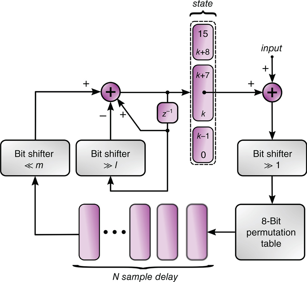
Figure 11.3 A Delay‐Filter‐Permute (DFP) block. For autonomous operation, the input and associated bit shifter in front of the permutation table are omitted.
11.2.1 The Delay‐Filter‐Permute Block
In Figure 11.3, we show the diagram of a digitally implementable “chaotic” delay system that we call a Delay‐Filter‐Permute block (DFP). Understandibly, a discrete‐time and discrete‐valued system cannot show deterministic chaos in the true sense, since the number of discrete states in the phase space is finite and therefore the dynamical behavior must eventually revisit these states. In contrast, a real‐valued chaotic system has infinitely dense orbits, which nevertheless take up a finite volume in its phase space. Such a collection of dense orbits is called a “strange attractor”. However, if the number of possible states in a discrete‐valued system is high, then very complex dynamical behavior could be observed if the state update rules allow for it. An example of this is found in feedback digital filters which can exhibit chaos‐like behaviors due to overflow, underflow or rounding [18]. In the scheme shown in Figure 11.3, this large phase space is obtained via a delay of ![]() 8‐bit values, having in total
8‐bit values, having in total ![]() possible states. The values in the delay originate from an 8‐bit in/8‐bit out permutation table, hence a bijective function
possible states. The values in the delay originate from an 8‐bit in/8‐bit out permutation table, hence a bijective function ![]() of the form:
of the form:
which is chosen at random, such that for ![]() we have
we have ![]() and
and ![]() . We did not need to place any special requirements on the construction of the random permutation table to reach the results reported below. If we exclude mapping values onto themselfves
. We did not need to place any special requirements on the construction of the random permutation table to reach the results reported below. If we exclude mapping values onto themselfves ![]() (because this would make the dynamical behavior less diverse), then it turns out there exists a staggering
(because this would make the dynamical behavior less diverse), then it turns out there exists a staggering ![]() choices to build this function. The delayed and permuted 8‐bit values are then bit‐shifted to the left by
choices to build this function. The delayed and permuted 8‐bit values are then bit‐shifted to the left by ![]() positions, i.e., multiplied by
positions, i.e., multiplied by ![]() . These are added to a 16‐bit “state” variable. By using an
. These are added to a 16‐bit “state” variable. By using an ![]() ‐bit right‐shift operation and a subtraction, a recursive lowpass filtering is performed on this state variable. The recursive nature of this filter gives it some memory, allowing it to mix the states of several delayed values. The input to the permutation table is given by the bitfield
‐bit right‐shift operation and a subtraction, a recursive lowpass filtering is performed on this state variable. The recursive nature of this filter gives it some memory, allowing it to mix the states of several delayed values. The input to the permutation table is given by the bitfield ![]() of the 16‐bit state variable, and these also form the key values of Figure 11.1. Several DFP blocks can be coupled by averaging the
of the 16‐bit state variable, and these also form the key values of Figure 11.1. Several DFP blocks can be coupled by averaging the ![]() bitfield with that originating from another DPF. Another method is to simply to let the sum of the
bitfield with that originating from another DPF. Another method is to simply to let the sum of the ![]() bitfields from two coupled DPFs overflow, and use the least significant eight bits as input to the permutation table. For autonomous operation, the input and divide‐by‐two shifter as shown in Figure 11.3 are omitted. In summary, the behavior of an autonomous DFP block answers to the following equation:
bitfields from two coupled DPFs overflow, and use the least significant eight bits as input to the permutation table. For autonomous operation, the input and divide‐by‐two shifter as shown in Figure 11.3 are omitted. In summary, the behavior of an autonomous DFP block answers to the following equation:
where ![]() denotes the 16‐bit state variable and the operation
denotes the 16‐bit state variable and the operation ![]() (
(![]() ) means shifting the binary representation of
) means shifting the binary representation of ![]() to the right (left) over
to the right (left) over ![]() positions, which is equivalent to dividing (multiplying)
positions, which is equivalent to dividing (multiplying) ![]() by
by ![]() , followed by rounding downwards to the nearest integer. In Eq. 11.3,
, followed by rounding downwards to the nearest integer. In Eq. 11.3, ![]() is the length of the delay line and “and” stands for the bitwise and‐ing operation. Clearly, the DFP is readily integrateable in an ASIC, FPGA or as embedded code. We note that a similar system, executed in two steps:
is the length of the delay line and “and” stands for the bitwise and‐ing operation. Clearly, the DFP is readily integrateable in an ASIC, FPGA or as embedded code. We note that a similar system, executed in two steps:
delivers qualitatively similar results as Eq. 11.3, while being slightly more easy to implement in hardware. Also, switching the permutation table and delay, does not alter the operation, apart from the entries in the delay line itself.

Figure 11.4 Dynamical behavior of the DFP for parameters  . a) Timetrace of the state variable
  of Eq. 11.3 at startup. Time is in units of the delay line length
  . b) Autocorrelation of the state. c) Return map
  . d) Return map
  . e) Histogram of the state and fit to a normal distribution from one million samples. f) Histogram of the values obtained from one million samples of the three least significant bits of the state. The dotted line indicates
  , the bin value for a theoretical uniform distribution.
In Figure 11.4, we present some exploratory data analysis on the dynamical behavior of a single DPF, Eq. 11.3, with the parameters set to ![]() . We emphasize that these values are merely exemplary. During our simulations we found that many other choices work just as well. In Figure 11.4a, we show the timetrace of the DFP. Here, time is shown in units of the delay line length,
. We emphasize that these values are merely exemplary. During our simulations we found that many other choices work just as well. In Figure 11.4a, we show the timetrace of the DFP. Here, time is shown in units of the delay line length, ![]() samples. Initially, the delay is filled with zeros and the state variable is also set to zero. After a startup transient of about
samples. Initially, the delay is filled with zeros and the state variable is also set to zero. After a startup transient of about ![]() samples, an irregular signal is seen. Of course, to make sure the system starts generating, it is required that
samples, an irregular signal is seen. Of course, to make sure the system starts generating, it is required that ![]() . By not allowing self mappings
. By not allowing self mappings ![]() , we ensure a short transient‐to‐steady state and what is loosely called a“rich” dynamical behavior. The autocorrelation, Figure 11.4b, has a single central peak with a width (at half maximum) of 22 samples, and a maximum height outside of the central peak, of 0.015. Clearly, there is no indication of a periodic component. Figure 11.4c shows a return map from one state value
, we ensure a short transient‐to‐steady state and what is loosely called a“rich” dynamical behavior. The autocorrelation, Figure 11.4b, has a single central peak with a width (at half maximum) of 22 samples, and a maximum height outside of the central peak, of 0.015. Clearly, there is no indication of a periodic component. Figure 11.4c shows a return map from one state value ![]() to the next,
to the next, ![]() . The wide central band indicates that one specific state value is in general preceded by many others. Often for chaotic delay systems, a suitable delay embedding reveals some structure reminiscent of the nonlinearity employed [19,20]. We have found this is not the case here, as for example the half‐delay return map
. The wide central band indicates that one specific state value is in general preceded by many others. Often for chaotic delay systems, a suitable delay embedding reveals some structure reminiscent of the nonlinearity employed [19,20]. We have found this is not the case here, as for example the half‐delay return map ![]() , shown in Figure 11.4d, reveals no recognizable structure. A histogram of the state derived from
, shown in Figure 11.4d, reveals no recognizable structure. A histogram of the state derived from ![]() samples, Figure 11.4e, shows a near‐perfect fit to a normal distribution with location
samples, Figure 11.4e, shows a near‐perfect fit to a normal distribution with location ![]() and root‐variance
and root‐variance ![]() .
.
11.2.2 Steady‐State Dynamics of the DFP
We can estimate these values and gain some insight into the DFP by rewriting Eq. 11.3. Using ![]() ,
, ![]() , thus ignoring flooring effects introduced by the bit shifters and finite 16‐bit precision leads to:
, thus ignoring flooring effects introduced by the bit shifters and finite 16‐bit precision leads to:
where we have written the delayed output of the permutation table as a variable ![]() . Taking the expectation of both sides:
. Taking the expectation of both sides:
and setting ![]() , yields:
, yields:
A histogram of the output of the permutation table (not shown) reveals that these values, interpreted as the realizations of a random variable ![]() , closely follow a uniform distribution with
, closely follow a uniform distribution with ![]() . Therefore
. Therefore ![]() and
and ![]() . Thus Eq. 11.8 yields
. Thus Eq. 11.8 yields ![]() , very close to the experimental result of 32660. In a similar fashion, we can calculate the variance of the state variable:
, very close to the experimental result of 32660. In a similar fashion, we can calculate the variance of the state variable:

Assuming state variable ![]() and output of the permutation table
and output of the permutation table ![]() are uncorrelated, results in:
are uncorrelated, results in:

After filling in the ![]() , we obtain
, we obtain ![]() , again very close to the experimental result (3386), shown in Figure 11.4e. By virtue of the central limit theorem, many averaged (or low‐pass filtered) uniformly distributed random variables add up to a normal distribution. This explains the shape of the state variable distribution as shown in Figure 11.4e.
, again very close to the experimental result (3386), shown in Figure 11.4e. By virtue of the central limit theorem, many averaged (or low‐pass filtered) uniformly distributed random variables add up to a normal distribution. This explains the shape of the state variable distribution as shown in Figure 11.4e.
11.2.3 DFP‐Bitstream Generation
In [11], we have introduced a method for generating an unbiased bitstream from an analog chaotic circuit. There, the bit value was chosen based on the comparison beween two values of the subsampled chaotic timeseries. This method could be applied here too. However, due to the highly irregular dynamical behavior of the DFP, a simpler method to generate random bits works as well. Here, we take the least significant bit of each sample of the state variable. In Table 11.1, we show the results of the National Institute of Standards test suite for random bit streams [21] on 50 million bits generated by this method. The random bits were divided in 50 sequences of 1 million bits each. The test suite was used with the default settings. Where a test has more than one result, both the highest and lowest results are shown. The results file states that the minimum pass rate for each statistical test, with the exception of the random excursion (variant) test, is approximately 47 for a sample size of 50 binary sequences. The minimum pass rate for the random excursion (variant) test is approximately 31 for a sample size of 34 binary sequences. We conclude that the bitstream thus generated by the LSB of the DFP state variable shows no sign of deviation from randomness.
Table 11.1 Results from the NIST randomness test suite, for the testing of 50 million bits obtained as the LSBs from the state variable of a DFP with parameters ![]() .
.
| Uniformity P‐value | Pass Ratio | Test |
| 0.616305 | 49/50 | Frequency |
| 0.911413 | 49/50 | BlockFrequency |
| 0.350485 | 49/50 | CumulativeSums (min) |
| 0.574903 | 49/50 | CumulativeSums (max) |
| 0.455937 | 49/50 | Runs |
| 0.699313 | 49/50 | LongestRun |
| 0.455937 | 50/50 | Rank |
| 0.613305 | 50/50 | FFT |
| 0.008879 | 48/50 | NonOverlappingTemplate (min) |
| 0.996335 | 50/50 | NonOverlappingTemplate (max) |
| 0.085587 | 49/50 | OverlappingTemplate |
| 0.419021 | 49/50 | Universal |
| 0.851383 | 49/50 | ApproximateEntropy |
| 0.054199 | 34/34 | RandomExcursions (min) |
| 0.911413 | 34/34 | RandomExcursions (max) |
| 0.000153 | 34/34 | RandomExcursionsVariant (min) |
| 0.911413 | 34/34 | RandomExcursionsVariant (max) |
| 0.030806 | 50/50 | Serial (min) |
| 0.096578 | 50/50 | Serial (max) |
| 0.319084 | 50/50 | LinearComplexity |

Figure 11.5 Two DFPs differing in a single swap in the permutation table, but otherwise identical. a) Transient at start up. b) Crosscorrelation. c) Power spectrum. d) Normalized distance of entries in the delay line.
11.2.4 Sensitivity to Changes in the Permutation Table
It is interesting to examine how sensitive the chaotic timeseries obtained from the DFP are with respect to changes in the permutation table. In Figure 11.5a, we show two signals of almost identical DFPs, again with parameters ![]() . The only difference beween them consists of two values that are swapped in the permutation table of one DFP. After an initial transient, the timeseries diverge completely. Their maximal crosscorrelation, shown in Figure 11.5b is 0.013, revealing no relation between the signals or the nearly identical systems they originated from. The power spectra, shown in Figure 11.5c, appear similar in nature. In Figure 11.5d, we show the normalized Euclidian distance of the
. The only difference beween them consists of two values that are swapped in the permutation table of one DFP. After an initial transient, the timeseries diverge completely. Their maximal crosscorrelation, shown in Figure 11.5b is 0.013, revealing no relation between the signals or the nearly identical systems they originated from. The power spectra, shown in Figure 11.5c, appear similar in nature. In Figure 11.5d, we show the normalized Euclidian distance of the ![]() ‐component vectors
‐component vectors ![]() ,
, ![]() formed by the delay line entries. This distance is calculated as:
formed by the delay line entries. This distance is calculated as:

where ![]() and
and ![]() represent the mean values. This illustrates that, after the transients the system states stay separated. In Figure 11.5d, the mean value of
represent the mean values. This illustrates that, after the transients the system states stay separated. In Figure 11.5d, the mean value of ![]() coincides with what is expected for two independent identically distributed normal random variables. From 1 million bits derived from the LSBs of both DFPs, we found that the fraction of equal bits was 0.500423. This is in line with what can be expected for two unrelated random bit generators. In addition, we found that negating even one single bit in the permutation table gave similar results. This suggests that every possible permutation table yields a completely different generator, which understandibly is a prominent feature of the DFP as a driving oscillator in an encryption system.
coincides with what is expected for two independent identically distributed normal random variables. From 1 million bits derived from the LSBs of both DFPs, we found that the fraction of equal bits was 0.500423. This is in line with what can be expected for two unrelated random bit generators. In addition, we found that negating even one single bit in the permutation table gave similar results. This suggests that every possible permutation table yields a completely different generator, which understandibly is a prominent feature of the DFP as a driving oscillator in an encryption system.
11.3 The Chaotic Followers
At this point, referring back to the system scheme of Figure 11.1, we might complete our encryption system by using one DFP as a driver and a different second and third DFP as followers. Two problems would arise from this approach. First, the fact that part of the driver states, namely the bitfield ![]() , is visible in the public channel, reveals some information about the driver's internal operation (note that many states coincide with a single value of this bitfield, as Figure 11.4c shows). Although in itself this need not be detrimental to our encryption scheme, it is still desirable that no information about the internal operation of the driver is derivable from what is publicly visible. To alleviate this problem, we will cascade two DFPs (called predriver and driver), via the input node shown in Figure 11.3, where the
, is visible in the public channel, reveals some information about the driver's internal operation (note that many states coincide with a single value of this bitfield, as Figure 11.4c shows). Although in itself this need not be detrimental to our encryption scheme, it is still desirable that no information about the internal operation of the driver is derivable from what is publicly visible. To alleviate this problem, we will cascade two DFPs (called predriver and driver), via the input node shown in Figure 11.3, where the ![]() ‐bitfield of the state of predriver and driver are averaged. We note that exclusive‐or‐ing of these bitfields also works and is probably a bit easier to implement. The dynamical behavior of the driver is then completely perturbed by the predriver, leading to results which we will not show in the interest of saving space, but which are strikingly similar to those shown in Figure 11.5. Note the states of the predriver are not visible in the public channel.
‐bitfield of the state of predriver and driver are averaged. We note that exclusive‐or‐ing of these bitfields also works and is probably a bit easier to implement. The dynamical behavior of the driver is then completely perturbed by the predriver, leading to results which we will not show in the interest of saving space, but which are strikingly similar to those shown in Figure 11.5. Note the states of the predriver are not visible in the public channel.
A second problem arises from the use of DFPs as followers: it requires the need to somehow synchronize the follower‐DFPs in both the receiver and transmitter so that they generate the same bitstream. From our experiments, identical driven DFPs do not synchronize when started from an arbitrary state. This difficulty could be overcome at a higher level in the communication protocol: on instantiating a transmission, both the transmitter and receiver agree to reset their follower‐DFPs and then run them for an arbitrary but predetermined time with bogus input, presented by the driver, to get past the initial transient. Afterward, the message can be securely exchanged. In the next section, we present an alternative method for constructing the followers, based on generalized synchronization.
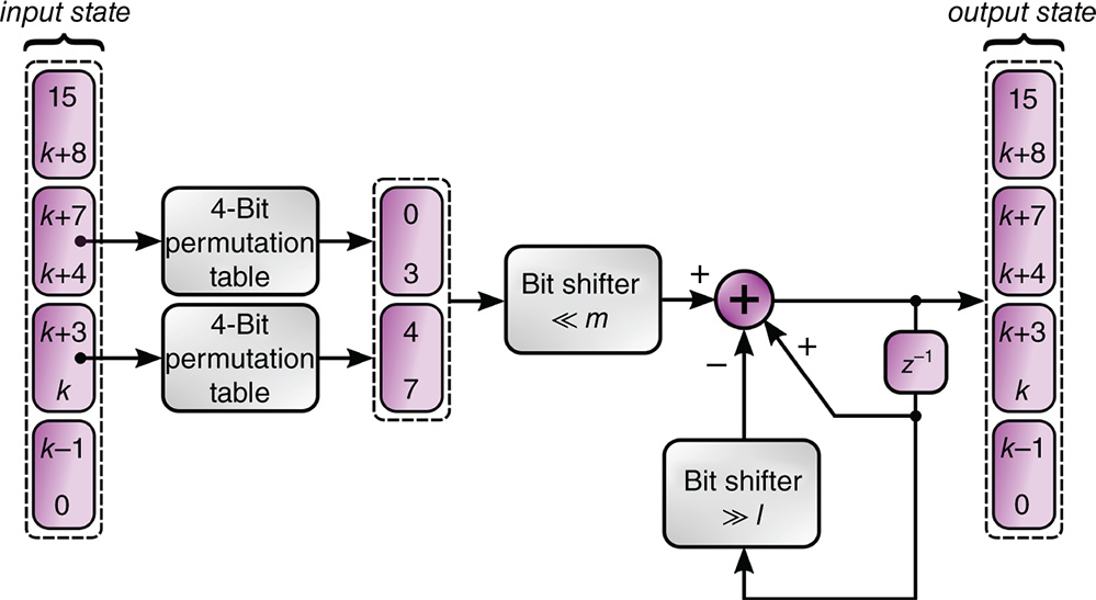
Figure 11.6 A single permutate‐filter (PF) block.
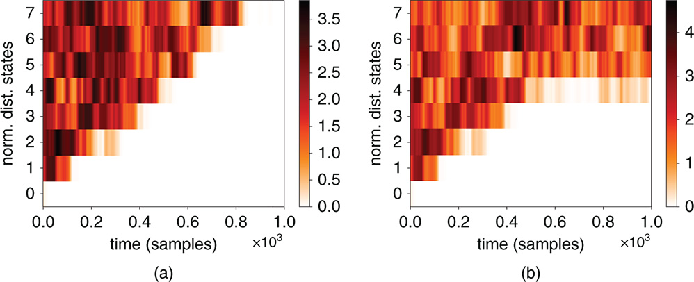
Figure 11.7 a) Synchronization of two identical followers, each having eight PF blocks, starting from a random state. b) Two almost identical followers, differing in a single permutation table swap in the fourth PF do not synchronize. The color‐intensity plot depicts the normalized Euclidian distance, over  samples (Eq. 11.11).
11.3.1 The Permute‐Filter Block
In Figure 11.6, we show what we call a permute‐filter (PF) block. Basically, this is a DFP missing the delayed self‐feedback. Each block, of which many are to be used in a single follower, has a single 16‐bit lossy filter. This results in a fading memory, which is a requirement for synchronization. Denoting ![]() as the number of PF blocks in the followers used in the next experiments are parameterized as
as the number of PF blocks in the followers used in the next experiments are parameterized as ![]() . Note that it is not necessary to have identical PF parameters in the individual blocks of a follower, nor do the bitfields of the input and output of the PF need to be identical, as is drawn in Figure 11.6. In Figure 11.7a we show how two identical followers synchronize, starting from random states. The color‐intensity plot depicts the normalized Euclidian distance, over 64 samples, between corresponding PF blocks in the two followers. One after the other, the PF blocks synchronize until both followers are entirely in sync. In contrast, if two values are swapped in one of the permutation tables, for example, in the fourth PF, then from this onward, the followers do not synchronize. This is shown in Figure 11.7b. Experimentally, we observed that the crosscorrelation between the outputs of the desynchronized followers stayed below
. Note that it is not necessary to have identical PF parameters in the individual blocks of a follower, nor do the bitfields of the input and output of the PF need to be identical, as is drawn in Figure 11.6. In Figure 11.7a we show how two identical followers synchronize, starting from random states. The color‐intensity plot depicts the normalized Euclidian distance, over 64 samples, between corresponding PF blocks in the two followers. One after the other, the PF blocks synchronize until both followers are entirely in sync. In contrast, if two values are swapped in one of the permutation tables, for example, in the fourth PF, then from this onward, the followers do not synchronize. This is shown in Figure 11.7b. Experimentally, we observed that the crosscorrelation between the outputs of the desynchronized followers stayed below ![]() , which is qualitatively similar to Figure 11.5b. Note that instead of using a single 8‐bit permutation table per PF block, two 4‐bit permutation tables which together form a single 8‐bit table are used. The reason for this is as follows. We want to maximize the effect of a difference in permutation table entries between two followers. On average, a single entry in a 8‐bit permutation table in a PF would get a “hit” once every
, which is qualitatively similar to Figure 11.5b. Note that instead of using a single 8‐bit permutation table per PF block, two 4‐bit permutation tables which together form a single 8‐bit table are used. The reason for this is as follows. We want to maximize the effect of a difference in permutation table entries between two followers. On average, a single entry in a 8‐bit permutation table in a PF would get a “hit” once every ![]() samples. Suppose we find ourselves in the situation where all PF blocks between two followers, except for the last one, are identical and this last PF would have only one bit error or one swap. Then by virtue of the feedforward nature of the PF many of its output samples would be correct. This might lead to parts of the message that are in between hits of the wrong value to be decoded correctly. Since for the 4‐bit permutation table the hit rate is
samples. Suppose we find ourselves in the situation where all PF blocks between two followers, except for the last one, are identical and this last PF would have only one bit error or one swap. Then by virtue of the feedforward nature of the PF many of its output samples would be correct. This might lead to parts of the message that are in between hits of the wrong value to be decoded correctly. Since for the 4‐bit permutation table the hit rate is ![]() ‐th, there is less time for this to happen. Alternatively, one can say that the overal 8‐bit permutation formed by the
‐th, there is less time for this to happen. Alternatively, one can say that the overal 8‐bit permutation formed by the ![]() 4‐bit tables changes in 16 places for every single change in a 4‐bit table. Understandibly, we pictured an extreme case, and using 8‐bit permutation tables in all PF blocks of a follower will offer adequate security. A mixed approach, where internal the PF blocks benefit from an 8‐bit permutation table, while the last block utilizes two 4‐bit tables is also possible. The downside of this approach is that there simply exist fewer 4‐bit permutation tables then 8‐bit ones.
4‐bit tables changes in 16 places for every single change in a 4‐bit table. Understandibly, we pictured an extreme case, and using 8‐bit permutation tables in all PF blocks of a follower will offer adequate security. A mixed approach, where internal the PF blocks benefit from an 8‐bit permutation table, while the last block utilizes two 4‐bit tables is also possible. The downside of this approach is that there simply exist fewer 4‐bit permutation tables then 8‐bit ones.
11.3.2 Brute Force Attack
Thus, one might wonder how difficult it is to break a follower consisting of a chain of eight PF blocks by brute force attack alone. Since each PF has two 4‐bit tables and we exclude identical mappings ![]() for
for ![]() , there are
, there are ![]() configurations for a single PF. Having eight PF blocks then delivers
configurations for a single PF. Having eight PF blocks then delivers ![]() possible follower configurations. The attack might be carried out using specialized computing hardware running in parallel. Solely for the purpose of a back‐of‐the‐envelope calculation, let's take the Cedar supercomputer (officially named GP2) at the Simon Fraser University in Canada as an example. This supercomputer, which was built in 2017, has been reported as having a theoretical peak performance of 3.6 petaflops in double precision. Let's assume that somehow this number equals the number PF configurations we can check per second. Obviously, this is a gross overestimation. To check all configurations then would take
possible follower configurations. The attack might be carried out using specialized computing hardware running in parallel. Solely for the purpose of a back‐of‐the‐envelope calculation, let's take the Cedar supercomputer (officially named GP2) at the Simon Fraser University in Canada as an example. This supercomputer, which was built in 2017, has been reported as having a theoretical peak performance of 3.6 petaflops in double precision. Let's assume that somehow this number equals the number PF configurations we can check per second. Obviously, this is a gross overestimation. To check all configurations then would take ![]() years. Clearly, a brute‐force attack is impractical. We stress that the strength of this method, as was the case for the system presented in [11], relies on the fact that the internal states of intermediate PF blocks are kept unobservable. A full identification and analysis of all possible attacks in a so‐called threat model is only useful given a more detailed practical implementation, where it is clear how this scheme is implemented in a protocol stack. We leave such analysis for future work.
years. Clearly, a brute‐force attack is impractical. We stress that the strength of this method, as was the case for the system presented in [11], relies on the fact that the internal states of intermediate PF blocks are kept unobservable. A full identification and analysis of all possible attacks in a so‐called threat model is only useful given a more detailed practical implementation, where it is clear how this scheme is implemented in a protocol stack. We leave such analysis for future work.
11.3.3 PF‐Bitstream Generation
In Table 11.2, we show the results of the NIST randomness test suite for the bitstream derived from the LSB of the state of the final PF in a chain of eight. This follower chain was driven by a predriver‐driver DFP cascade as described above. We obtained 50 million bits to derive these results. The results file states that the minimum pass rate for the random excursion (variant) test is approximately 29 for a sample size of 31 binary sequences. All tests are passed. We conclude that the bitstream generated by the followers shows no sign of deviation from randomness. In the next section, we show how the DFPs and PFs are brought together to form a complete encryption system.
Table 11.2 Results from the NIST randomness test suite, for the testing of 50 million bits obtained as the LSBs from the output of a chain of PF blocks, having parameters ![]() .
.
| Uniformity P‐value | Pass Ratio | Test |
| 0.739918 | 50/50 | Frequency |
| 0.051942 | 50/50 | BlockFrequency |
| 0.657933 | 50/50 | CumulativeSums (min) |
| 0.883171 | 50/50 | CumulativeSums (min) |
| 0.955835 | 50/50 | Runs |
| 0.058984 | 50/50 | LongestRun |
| 0.419021 | 50/50 | Rank |
| 0.455937 | 49/50 | FFT |
| 0.020548 | 50/50 | NonOverlappingTemplate (min) |
| 0.991468 | 50/50 | NonOverlappingTemplate (max) |
| 0.998821 | 49/50 | OverlappingTemplate |
| 0.171867 | 49/50 | Universal |
| 0.983453 | 50/50 | ApproximateEntropy |
| 0.015963 | 31/31 | RandomExcursions (min) |
| 0.706149 | 31/31 | RandomExcursions (max) |
| 0.110952 | 31/31 | RandomExcursionsVariant (min) |
| 0.834308 | 31/31 | RandomExcursionsVariant (max) |
| 0.699313 | 50/50 | Serial (min) |
| 0.699313 | 50/50 | Serial (max) |
| 0.319084 | 49/50 | LinearComplexity |
11.4 The Complete System
Note that in a practical setup a single communication can contain both the payload data as well as an encrypted identifier of the originator, thus combining authentication and encryption. For readability, we introduce these usages separately.
11.4.1 Image Encryption Example
In Figure 11.8, we show the completed system, utilizing the DFP and PF blocks described above. The example images in this figure are actual results from our numerical experiments. The source image is serialized and encrypted by XOR‐ing with the bitstream resulting from the LSB of the output state of follower 1. Follower 1 had parameters ![]() in our experiments, as discussed above. Follower 1 is driven by the ouput of a predriver‐driver cascade of two DFPs with parameters
in our experiments, as discussed above. Follower 1 is driven by the ouput of a predriver‐driver cascade of two DFPs with parameters ![]() and
and ![]() respectively. Clearly, the encrypted image resembles random noise. Follower 3 acts as an in‐channel eavesdropper, attempting to decrypt the image. Follower 3 has the exact same parameters as those used to illustrate the desynchronization in Figure 11.7b: it is a single permutation table swap removed from being identical to followers 1 and 2. The image as decoded by follower 3 is completely unintelligable, while follower 2, in synchronization with follower 1, perfectly decrypts the image.
respectively. Clearly, the encrypted image resembles random noise. Follower 3 acts as an in‐channel eavesdropper, attempting to decrypt the image. Follower 3 has the exact same parameters as those used to illustrate the desynchronization in Figure 11.7b: it is a single permutation table swap removed from being identical to followers 1 and 2. The image as decoded by follower 3 is completely unintelligable, while follower 2, in synchronization with follower 1, perfectly decrypts the image.

Figure 11.8 Image encryption using the proposed scheme based on generalized synchronization between two chains of permute‐filter blocks, driven by delay‐filter‐permute blocks.
11.4.2 Usage for Authentication
It is clear that the same scheme can just as easily be applied for authentication, as part of the message can relay the identity of the transmitter. This is illustrated in Figure 11.9. Here, the initiator of the authentication (for example, a sensor network base station) prompts a “challenge” key, which the receiving party uses, via its PF chain, to transcribe its identity and additional payload data (for example, temperature sensor data). This encrypted message is then sent back to the initiator through the public channel. The initiator then uses his own PF chain to decode and verify the encrypted data and identity that was returned. This is possible because the initiator can construct the exact same bit sequence via its own PF follower, which is identical to that of the originator of the data. Using suitably long keys ensures that no two similar keys will ever be repeated. The follower chains in both the initiator and responder should first be synchronized, either by driving them long enough or by a signalling at a higher protocol level, as explained earlier.

Figure 11.9 Authenticated transmission: the veracity of the origin of the response is guarantueed by having the data signed with the responder's identity. Upon decoding the response, the initiator checks the identity agains known‐good responders.
11.5 Conclusions and Outlook
We have demonstrated an encryption and authentication scheme based on generalized synchronization of complex systems. The building blocks of these systems are straightforward to implement in FPGAs and digital ASICs or as embedded code. The strength of the system hinges critically on the unobservability of the internal states of a strongly nonlinear system having a high‐dimensional phase space. The delay‐filter‐permute block has been shown to be an excellent random‐number generator, and it has been shown that two chains of identical permute‐filter blocks synchronize, while the slightest change in internal structure leads to complete decorrelation of the generated bitstreams. We emphasize that many design choices are still open to examination, as the parameters we have used in our numerical experiments are merely motivated by “what works” in a first demonstration. We have not yet systematically investigated the relation between cycle length and DFP delay memory length. This relation needs to be made clear in order to be able to optimize a practical proof‐of‐concept implementation. Another avenue of further research is to examine the possibility of generating several bits per transmitted key value, such that the bandwidth efficiency of the system is improved. A blunt method would be to have several PF chains working in parallel, however, this would not be very hardware efficient. As mentioned above, it is possible to generate bitstreams from other than the LSB of the final PF block in a follower chain, perhaps even from intermediate PF states. Obviously, there are many possible topologies to examine. Nevertheless, we have shown that the scheme that was introduced in [11] using analog electronics, can readily be ported to digital hardware. We conclude by remarking that complex systems are increasingly seen as alternative computational resources (for example in the field of Reservoir Computing [12], instead of mere system‐dynamical curiosities to be studied in isolation. We expect all future technologies, not only IoT, to benefit from their application and have aimed show the practical viability of one such scheme.
Acknowledgements
LK and GVDS were partly supported by the Belgian Science Policy Office under Grant No IAP‐7/35 “Photonics@be” and by the Science Foundation ‐ Flanders (FWO). GVDS thanks the Research Council of the VUB.
Author Contributions Statement
The concept originated from discussions between GVDS and LK. LK performed the numerical experiments. Both authors contributed to the manuscript.
Additional Information
The authors declare no competing financial interests.
References
- 1 Vernam, G.S. (1926). Cipher Printing Telegraph Systems For Secret Wire and Radio Telegraphic Communications. Journal of the IEEE 55: 109–115.
- 2 Pappu, R., Recht, B., Taylor, J. and N. Gershenfeld. (2002). Physical One‐Way Functions. Science 297 (5589): 2026–2030.
- 3 Gassend, B., Clarke, D., Van Dijk, M. and Devadas, S. (2002). Silicon physical random functions. Proceedings of the 9th ACM conference on computer and communications security, Washington, USA (18–22 November 2002). ACM.
- 4 Herder, C., Yu, M.D., Koushanfar, F. and Devadas, S. (2014). Physical unclonable functions and applications: a tutorial. Proceedings of the IEEE 102 (8): 1126–1141.
- 5 Rűhrmair, U. and Holcomb, D.E. (2014). Pufs at a glance. Proceedings of the conference on Design, Automation and Test in Europe, European Design and Automation Association, Dresden, Germany (24–28 March 2014). IEEE.
- 6 Rűhrmair, R., Sehnke, F., Sölter, et al. (2010). Modeling attacks on physical unclonable functions. Proceedings of the 17th ACM Conference on computer and communications security, Chicago, USA (04–08 October 2010). ACM.
- 7 G. T. Becker, (2015). The gap between promise and reality: On the insecurity of xor arbiter pufs. In: Cryptographic Hardware and Embedded Systems –CHES 2015 (eds. T. Gűneysu, and H. Handschuh), 535–555. Berlin, Heidelberg: Springer.
- 8 Cuomo, K.M., Oppenheim, A.V. and Strogatz, S.H. (1993). Synchronization of Lorenz based chaotic circuits with applications to communications. IEEE Transactions on Circuits and Systems II: Analog and Digital Signal Processing 40 (10): 626–633.
- 9 Argyris, A., Syvridis, D., Larger, L. et al. (2005). Chaos‐based communications at high bit rates using commercial fiber‐optic links. Nature 438: 343–346.
- 10 Porte, X., Soriano, M.C., Brunner, D. and Fischer, I. (2016). Bidirectional private key exchange using delay‐coupled semiconductor lasers. Optics Letters 41 (12): 2871–2874.
- 11 Keuninckx, L., Soriano, M.C., Fischer, I. et al. (2017). Encryption key distribution via chaos synchronization. Scientific Reports 7: 43428.
- 12 Keuninckx, L., Danckaert, J. and der Sande, G.V. (2017). Real‐time Audio Processing with a Cascade of Discrete‐Time Delay Line‐Based Reservoir Computers. Cognitive Computation 9 (11): 10.1007/s12559‐017‐9457‐5.
- 13 Oliveira, H.M. and Luas, L.V. (2015). Huygens synchronization of two clocks. Scientific Reports 5: 11548.
- 14 di Pellegrino, G., Fadiga, L., Fogassi, L. et al. (1992). Understanding motor events: a neurophysiological study Experimental Brain Research 91: 176–180.
- 15 Strogatz, S.H. (2001). Nonlinear dynamics and chaos: With applications to physics, biology, chemistry, and engineering. New York, NY: Perseus books.
- 16 Kato, H., Soriano, M.C., Pereda, E. et al. Limits to detection of generalized synchronization in delay‐coupled chaotic oscillators. Physical Review E 88 (6–1): 062924.
- 17 Soriano, M.C., Garcia‐Ojalvo, J., Mirasso, C.R. and Fischer, I. (2013). Complex photonics: dynamics and applications of delay‐coupled semiconductor lasers. Reviews of Modern Physics 85: 421–470.
- 18 Ogorzalek, M.J. (1997). Chaos and Complexity in Nonlinear Electronic Circuits. Singapore: World Scientific Publishing.
- 19 Mackey, M.C. and Glass, L. (1977). Oscillation and chaos in physiological control systems. Science 197 (4300): 287–289.
- 20 Van der Sande, G., Soriano, M.C., Fischer, I. and Mirasso, C.R. (2008). Dynamics, correlation scaling, and synchronization behavior in rings of delay‐coupled oscillators. Physical Review E 77 (5): 055202.
- 21 Bassham, L.E., Rukhin, A.L., Soto, J. et al. (2010). A statistical test suite for random and pseudorandom number generators for cryptographic applications. Technical Report, National Institute of Standards & Technology, Gaithersburg, MD, USA. https://ws680.nist.gov/publication/get_pdf.cfm?pub_id=906762 (accessed 25 June 2019).