
3
Symmetric Key‐Based Authentication with an Application to Wireless Sensor Networks
An Braeken
Abstract
This chapter starts with an introduction on different methods to provide key establishment and authentication using symmetric key‐based mechanisms limited to hashing, xoring and encryption/decryption operations. Based on an idea coming from the context of multi‐server authentication, and already applied in several IoT contexts, we present a new key management protocol for wireless sensor networks with hierarchical architecture, using solely symmetric key‐based operations. The protocol establishes confidentiality, integrity, and authentication. It supports various communication scenarios, has limited storage requirements, is highly energy efficient by minimizing the number of communication phases and cryptographic operations, and avoids message fragmentation as much as possible. With the pre‐installation of an individual secret key with the base station and some additional key material different for cluster head and cluster node, all possible keys in the network can be efficiently on‐the‐fly computed and updated. We discuss the differences with the well‐known LEAP key management system for wireless sensor networks.
3.1 Introduction
When a common secret is shared between two entities, symmetric key schemes in authenticated encryption (AE) mode, like for instance AES‐GCM or AES‐CCM, can be applied. However, in order to construct such an authenticated key, called the session key, either public key‐based or symmetric key‐based mechanisms can be used. The advantage of symmetric key‐based mechanisms is that they require much less computational efforts and smaller messages, compared to the public key‐based variants. The main challenge is how to efficiently construct this key in a scalable way. For instance, it would be very impractical if the device needs to store secret information corresponding to each different device with which it wants to communicate. Typically, a trusted third party (TTP) is involved in these protocols in order to manage the process.
There are different architectures to be considered, either a one‐to‐one communication or one‐to‐many communication setting. In a one‐to‐one communication, two devices construct a common secret key, with the aid of the TTP. Each device only needs to share a secret key with the TTP. The Needham‐Schroeder protocol [1] solves this problem. However, this protocol was found to be vulnerable for a replay attack [2], and was finally fixed in order to lead to the symmetric variant of the Kerberos protocol [3].
Recently, many advances have been made in protocols describing one‐to‐many communication. In particular, the two‐factor and three‐factor based multi‐server login protocols have evolved a lot since 2016, by including, in addition, anonymity and untraceability features [4]. These protocols can very easily be adopted in an IoT setting. For instance, in [5], we have shown how the technique can be used to provide different stakeholders (residents, recurring guests, or temporary guests) end‐to‐end secure access to the IoT devices in a smart home, managed by the home owner in an anonymous way. Here, the IoT devices take the role of gateway, receiving the requests from stakeholders who are in possession of a user device and thus enable two‐factor or three‐factor authentication. In [6], we also address the smart home scenario, but describe a key construction between IoT devices and gateway guaranteeing anonymity of the IoT device, without direct involvement of users. Consequently, the role of the IoT device in both [5] and [6] is different.
In this chapter, we want to demonstrate how the same idea can be used to construct a key management protocol for wireless sensor networks (WSNs), being an important part of IoT. The popularity of WSNs has grown tremendously during the last decade, due to the multitude of application areas. Security in these networks has also been extensively researched and standardized. However, these standardizations often do not include mechanisms for key management. Nevertheless, key management is essential in this whole procedure in order to send secure and authenticated messages. Minimal security features to be established are confidentiality, integrity, and authentication. Efficient mechanisms are required, due to the limited bandwidth, processing power, storage capacities, and battery age. Efficiency implies scalability and adjustability [7]. Scalability in the sense that the key management protocol is able to include additional nodes in a secure manner during the network's lifetime. Adjustability implies a proper mechanism to deal with network condition changes.
The key management protocol proposed in this chapter, called symmetric authenticated key agreement (SAK), is for sensor networks with a hierarchical architecture, consisting of base station (BS), cluster heads (CHs), and cluster nodes (CNs). Only symmetric key‐based operations are used to establish confidentiality, integrity, and authentication. Based on a preshared individual key between each sensor node and the BS and some additional key material different for CN and CH, secret keys are derived between CN and CH, two CNs of the same cluster, a group key among all the CHs and the BS, a group key among all CNs belonging to a certain CH, and a group key among a selected group of CNs inside a cluster.
The mechanisms to derive these keys are constructed in such a way that the number of communication phases among the involved entities and message fragmentation is limited as much as possible. Moreover, the storage requirements for the key derivation in each entity is very small, related to other previous work. If a node is captured, then awaiting the update of the BS for each individual node in the cluster, a change mode is proposed to derive new values for the keys among all trusted nodes in the same cluster with and without the CH.
The remainder of the chapter is organized as follows. Section 3.2 provides an overview of the related work in key management protocols for WSNs. Section 3.3 explains the network architecture with some key definitions and assumptions used. In Section 3.4, we explain the different phases of our scheme in normal mode in detail. We show how to include authentication in Section 3.5. Section 3.6 discusses the system in change mode, offering an answer to situations where the system is attacked or where a node changes its place, is added, or removed from the network. Sections 3.7 and 3.8 respectively describe the security analysis and the corresponding efficiency. Finally, section 3.9 concludes the paper.
3.2 Related Work
Key management in wireless sensor networks is already extensively described for both distributed and hierarchical architectures of the nodes [8,9]. We focus on the last one, since it was shown to be more energy‐efficient and performant [10,11]. In general, there are three main approaches for key management, using symmetric key cryptography, public key cryptography, and hybrid. Especially, in a hierarchical architecture, it can make sense to use a hybrid approach where the most computational heavy operations are performed by the CH. Often, authentication and integrity are obtained by digital signatures. However, as there is a huge performance difference between symmetric key and public key cryptography, it is still interesting to look at symmetric key‐based solutions, due to the limited energy, communication bandwidth, and computational capacities of the sensor nodes.
There have been several proposals published for symmetric key‐based hierarchical wireless sensor networks. Within the domain of symmetric‐key based, authenticated key management protocols, the Localized Encryption and Authentication Protocol (LEAP) [12] is the most complete one. It describes procedures to derive keys for the most common communication scenarios, being between two CNs, a group key for all nodes in a cluster, and a network key among all nodes. A detailed efficiency comparison between LEAP and our protocol is given in Section 3.8.
References [13,14] present randomized approaches for the key management, which have no guarantee of successful key establishment but limit the impact of a compromised node. Both protocols ([13,14]) have huge storage requirements in each of the nodes in the network.
Partial solutions for authenticated symmetric key‐based solutions can be found in [15–18]. In [15], a method using one‐way functions is explained to derive an authenticated pairwise key between CN and CH. Group keys are not derived in this paper. In [16], each node receives, dependent of its place in the sensor topology, an evaluation of a point on a pre‐defined bivariate polynomial of the BS. For the computation of the group key, Lagrange interpolation is used, but a lot of unicast communications are required to send the group key to the individual members. Moreover, no method is explained on how to use this group key in an authenticated way. Finally, the key management in [17,18] is based on a generator matrix, predefined at the BS. The computation of the group key requires the involvement of the BS and cannot be performed by the CH alone. Again no mechanism is described to guarantee authenticated usage of the group key. In addition, the protocols from [15–18] are restricted to star networks, and thus no mechanism is described to compute a shared key between two CNs of the same cluster.
For our protocol, we use a trick where CNs and their corresponding CH share different content, that when combined uniquely determines the sender of a message. As explained before, this idea is inspired from a protocol for a biometric‐based multi‐server login [4].
3.3 System Model and Assumptions
3.3.1 Design Goals
The design goals of SAK are similar to LEAP [12] and should satisfy the following criteria.
- – SAK should support authentication, integrity, and confidentiality for the most common communication scenarios. These include the communication between two CNs of the same cluster, between a CN and a CH, among nodes in the same cluster, among all the nodes in the network.
- – If one or a limited number of sensor nodes are compromised, the entire network should still be able to‐survive further with a limited number of adaptations.
- – Due to the resource‐constrained nature of the sensor nodes, the protocol should be designed as efficiently as possible. This aims a to minimize the communication phases and the number of expensive cryptographic operations as much as possible.
- – As there is a relatively high packet loss in sensor networks, message fragmentation should be avoided as much as possible. Using the adaptation layer 6LoWPAN for the compression of IP headers, a payload can contain approximately 70 bytes [19].
3.3.2 Setting
We consider a sensor network with a three‐layered architecture, being the BS, the ![]() nodes
nodes ![]() , and the CNs
, and the CNs ![]() belonging to a particular CH
belonging to a particular CH ![]() . Let us assume that each sensor node (CHs and CNs) participating in the network, has a pre‐installed secret shared key with the BS, an identifier, some auxiliary key material derived from the identifier and different in structure for CHs and CNs, and a common network key
. Let us assume that each sensor node (CHs and CNs) participating in the network, has a pre‐installed secret shared key with the BS, an identifier, some auxiliary key material derived from the identifier and different in structure for CHs and CNs, and a common network key ![]() . This information is stored in each sensor node, before the node is put into the field. The position of the nodes, i.e. combination of CN and CH, does not need to be known in advance, only the fact that a node will behave as CH or CN. Since CHs need to perform a considerably higher amount of processing, more powerful nodes are used for this task and distinction is easy.
. This information is stored in each sensor node, before the node is put into the field. The position of the nodes, i.e. combination of CN and CH, does not need to be known in advance, only the fact that a node will behave as CH or CN. Since CHs need to perform a considerably higher amount of processing, more powerful nodes are used for this task and distinction is easy.
Once the nodes are put in the field, the CH broadcasts its identity ![]() and a timestamp
and a timestamp ![]() . Next, the key management protocol will describe how each node
. Next, the key management protocol will describe how each node ![]() will be able to construct three on‐the‐fly‐different types of keys.
will be able to construct three on‐the‐fly‐different types of keys.
- – Group node key
 . This key is shared among all nodes and CH in the cluster with CH,
  .
. - – Multicast key
 : This key is shared among a selected group of nodes
  by the CH
  .
. - – Individual cluster key
 . This key is uniquely shared between
  and the CH
  .
. - – Pairwise key
 . This key is shared between the nodes
  and
and  in the same cluster.
When the BS sends a timestamp ![]() to the CHs in the network, the CHs are also able to derive a group key shared among the CHs and the BS, called the group cluster key
to the CHs in the network, the CHs are also able to derive a group key shared among the CHs and the BS, called the group cluster key ![]() . In addition, the CH can also derive on‐the‐fly the group node key
. In addition, the CH can also derive on‐the‐fly the group node key ![]() , the multicast key
, the multicast key ![]() , and the individual cluster key
, and the individual cluster key ![]() . Moreover, we also explain how we include authentication into the communication. Fig. 3.1 illustrates the involved entities for examples of different types of keys.
. Moreover, we also explain how we include authentication into the communication. Fig. 3.1 illustrates the involved entities for examples of different types of keys.

1 This figure shows an example of the different possible keys in the scheme with base station BS, cluster head  and corresponding cluster nodes
  . The network key is denoted by
  , the group node key by
  , the multicast key by
  , the pairwise key by
  and the individual cluster key by
  .
.
The communication capacity between the different entities in the nodes differs due to the difference in resources. The BS can in any case unicast or broadcast information directly to the CHs or the CNs. A CH communicates to the BS in a multi‐hop way, while it is able to unicast or broadcast directly to all nodes in its cluster. A sensor node communicates to its CH in single hop or multiple‐hop, dependant on its distance.
3.3.3 Notations
We represent a hash function by ![]() . The encryption operation of message
. The encryption operation of message ![]() under a key
under a key ![]() to obtain the ciphertext
to obtain the ciphertext ![]() is denoted as
is denoted as ![]() , and the corresponding decryption operation as
, and the corresponding decryption operation as ![]() . Furthermore, the concatenation of values
. Furthermore, the concatenation of values ![]() and
and ![]() is denoted by
is denoted by ![]() and the xor operation by
and the xor operation by ![]() .
.
3.3.4 Attack Model
The attackers may come from inside or outside the network. They are able to eavesdrop on the traffic, inject new messages, replay and change old messages, or spoof other identities. They may try to take the role of CN or CH.
Attackers can also compromise and capture a node, such that all security material is revealed. Note that we do not discuss the mechanisms to detect malbehavior of a node, e.g. by storing trust tables in each node. Therefore, we refer to the literature on intrusion detection mechanisms [20] to detect abnormal behaviour of a compromised node. On the other hand, we describe how to act when such a situation occurs, corresponding to the description of the scheme in change mode, Section 3.6.
3.4 Scheme in Normal Mode
We first describe how the scheme works in normal mode, meaning no real threats or indications exist to assume a node is behaving maliciously. In the next section, we explain how to deal otherwise, called the scheme in change mode.
Several phases in the key management scheme are distinguished. First, there is the installation phase, where every node is installed with a unique individual shared key with the BS, the network key, and some auxiliary key material different for CN and CH. This information is independent of the final location in the network. It only requires the knowledge of role the sensor is going to play, either CN or CH. Note that the BS acts as TTP.
The following phases correspond with the construction of the different types of keys, using this key material. We distinguish the derivation of the group node key, the individual cluster key, the pairwise key, the multicast key, and the group cluster key. In Section 3.5, we also explain how authentication is obtained in the scheme. These different phases are now described into more detail.
3.4.1 Installation Phase
The installation differs for CH and CN. We will discuss both types. Let ![]() and
and ![]() be two master secret keys of the BS.
be two master secret keys of the BS.
3.4.1.1 Installation of CH
The following material is installed at each CH, called ![]() .
.
- – The network key
 .
. - – The identifier
 .
. - – An individual shared key with the BS, being
 . In order to decrease the storage requirements of the BS, these keys can be derived from a master key
  and the corresponding identity of the node, i.e.
 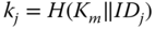 .
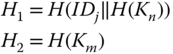
. - – The auxiliary key material consists of
(3.1)
3.4.1.2 Installation of CN
The following material is installed at each CN.
- – The network key
 .
. - – The individual shared key with the BS,
 .
. - – Define
(3.2)

Then, the following auxiliary key material, is also stored at each CN.
(3.3)

Note that any direct reference to the original identity ![]() is removed from the node's memory. From now on, the node will communicate under the identity
is removed from the node's memory. From now on, the node will communicate under the identity ![]() . Consequently, the supplier is not able to follow its nodes in the network. In order to increase the difficulty of a node's capture attack, we will show later that it is sufficient only to protect
. Consequently, the supplier is not able to follow its nodes in the network. In order to increase the difficulty of a node's capture attack, we will show later that it is sufficient only to protect ![]() and
and ![]() by means of software obfuscating techniques, for example [22,23]. We consider these measures outside the scope of this paper.
by means of software obfuscating techniques, for example [22,23]. We consider these measures outside the scope of this paper.
Finally, we also want to draw attention to the division of the key material. Both CH and CN each possess one secret master key of the BS and a variable which is derived from the other secret master key.
3.4.2 Group Node Key
The CH first chooses a random value ![]() and computes the group key
and computes the group key
The CH ![]() broadcasts
broadcasts ![]() .
.
All the CNs in the neighbourhood of ![]() can now easily derive this group key. First the message is decrypted using the network key. Then,
can now easily derive this group key. First the message is decrypted using the network key. Then, ![]() is extracted from
is extracted from ![]() and used to construct the group key,
and used to construct the group key, ![]() (see Equation 3.4). The result is compared with the last part of the decrypted message in order to verify the integrity.
(see Equation 3.4). The result is compared with the last part of the decrypted message in order to verify the integrity.
This process is typically initiated by the CH, but can in theory also be activated by another CN. We show in Section 3.5 how authentication of the CH can be included in this process and how the CH can use this key in an authenticated way.
3.4.3 Individual Cluster Key
This phase leads to the derivation of the individual shared key ![]() between
between ![]() and
and ![]() and requires only one communication phase between
and requires only one communication phase between ![]() and
and ![]() . We may assume here that
. We may assume here that ![]() is aware of the identity
is aware of the identity ![]() of
of ![]() , since it has received the broadcast message
, since it has received the broadcast message ![]() from the previous step. We now describe in more detail the different steps to be performed by the participants. There are two possibilities, either initiated by the CN or the CH.
from the previous step. We now describe in more detail the different steps to be performed by the participants. There are two possibilities, either initiated by the CN or the CH.
3.4.3.1 CN to CH
The following steps are executed by ![]() .
.
- – First
 is derived from
  .
. - – In addition,
 also computes from its stored values
(3.5)
also computes from its stored values
(3.5)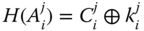
- – Next,
 chooses a random value
  , which will serve as an individual cluster key and computes:

- – The following message is then sent to
 :
(3.6)
:
(3.6)
The ![]() receives this message and performs the following computations:
receives this message and performs the following computations:
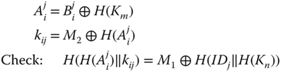
This check corresponds with an identity check since only the node with the correct pre‐installed values by the BS is able to derive the identity related information in the form of ![]() . In addition, the integrity on the derived key is also verified. Only if the right value for
. In addition, the integrity on the derived key is also verified. Only if the right value for ![]() is found, this equality holds. If the check is positive, then
is found, this equality holds. If the check is positive, then ![]() can conclude that the node with identifier
can conclude that the node with identifier ![]() belongs to the network and its corresponding shared key equals to
belongs to the network and its corresponding shared key equals to ![]() .
.
3.4.3.2 CH to CN
We now assume that the CH is aware of the presence of the CN ![]() in its cluster. For instance, the CN could have already sent some information to the CH before, as shown in the previous step. The CH then performs the following steps to derive the individual cluster key.
in its cluster. For instance, the CN could have already sent some information to the CH before, as shown in the previous step. The CH then performs the following steps to derive the individual cluster key.
- – The CH first extracts
 from the sensor node's public parameter
  , by
, by  .
. - – In order to add randomness to it, a random parameter
 is chosen and the individual cluster key is defined by
(3.7)
is chosen and the individual cluster key is defined by
(3.7)
Note that the last part is required to make sure only CH
 is able to establish this message.
 - – The CH sends to the CN
 (3.8)
(3.8)
The CN ![]() receives this message and computes
receives this message and computes ![]() (Equation 3.5) and the value
(Equation 3.5) and the value ![]() . Consequently, the shared key
. Consequently, the shared key ![]() from Equation 3.7 can be determined. Finally, in order to check the integrity of the key, the value
from Equation 3.7 can be determined. Finally, in order to check the integrity of the key, the value ![]() is computed and checked with the last part of the received message. If the integrity control is positive, then
is computed and checked with the last part of the received message. If the integrity control is positive, then ![]() can conclude that the CH
can conclude that the CH ![]() wants to share the key
wants to share the key ![]() .
.
3.4.4 Pairwise Key Derivation
Here, node ![]() establishes a key with
establishes a key with ![]() . There is a straightforward way to realize this if you let the CH generate the key and securely send it to the involved nodes in its cluster using
. There is a straightforward way to realize this if you let the CH generate the key and securely send it to the involved nodes in its cluster using ![]() and
and ![]() . However, we propose a protocol here that allows the construction of a pairwise key, only shared between the sensor nodes and not with the CH.
. However, we propose a protocol here that allows the construction of a pairwise key, only shared between the sensor nodes and not with the CH.
The idea is based on the fact that the nodes of the cluster and not the CH share the secret value ![]() . On the other hand, the CH shares with each individual node the value
. On the other hand, the CH shares with each individual node the value ![]() . Consequently, the node
. Consequently, the node ![]() needs to request unique information from the CH (based on
needs to request unique information from the CH (based on ![]() ) on node
) on node ![]() , corresponding with phase 1. If
, corresponding with phase 1. If ![]() is correctly authenticated, this info is sent from CH to
is correctly authenticated, this info is sent from CH to ![]() in phase 2, which puts
in phase 2, which puts ![]() in the knowledge of uniqe information only shared by
in the knowledge of uniqe information only shared by ![]() . Finally in phase 3, the key can be constructed using this information and the value
. Finally in phase 3, the key can be constructed using this information and the value ![]() by
by ![]() in order to uniquely share a key with
in order to uniquely share a key with ![]() without involvement of the CH. Let us now describe these three phases into more detail.
without involvement of the CH. Let us now describe these three phases into more detail.
- – Phase 1:
 Here,
Here,  requests some unique information, able to distinguish
  from the cluster group. Therefore, it first generates a random value
  and sends a key request
  . The first part of the message is to derive the individual cluster key
  as described in Equation 3.6.

- – Phase 2:

 first derives the key
  as described in the previous paragraph. Then, if
  can correctly decrypt the last part of the message, the following computations are performed:
- A new value for
 .
. - A value to distinguish
 , asked by
  :
:  . Only the CH is able to compute this value since the other CNs have no knowledge on
  .
.
The value
 is sent to
  .
. - A new value for
- –
 First, the key
  should be derived, as explained in the previous paragraph, in order to decrypt the message. Note that instead of sending
  as in Equation 3.8, only a ciphertext is sent. If after decryption, the first part of the plain text contains the random value
  , the integrity of the key is verified.
Next, a random value
 is chosen, which will serve as pairwise key. An additional random value
  is chosen. Now, the following computations are performed.
The values
 are sent to
  .
. - – Phase 3: Key derivation by
 In the last step, the receiver node
  , starts with decrypting the last part of
  , by computing the key
  . If the last part of the decrypted message is equal to the random value
  , the node
  concludes that the key request is coming from a validated node of the cluster since only the CH is able to compute the value of
  . The originator of the message is verified since it is included in the key computation. After successful decryption, the node
  can continue its computations with the random value
  from
from  . From
  , the key
  can be easily computed. Finally, the integrity of the key is checked with comparing the outcome of the message
  and the received
  .
.
3.4.5 Multicast Key
In case of doubt on the trust of the CNs in its network, it might be interesting, for example, for the CH to select the group of receivers. Another possibility might be that the message is only meant for nodes with a certain functionality or a certain property. We describe the operations performed by the CH and the operations by the CNs.
3.4.5.1 Initiation by CH
Suppose there are ![]() nodes in the cluster, with identities
nodes in the cluster, with identities ![]() . The CH,
. The CH, ![]() , chooses a random key
, chooses a random key ![]() . The following steps are now performed:
. The following steps are now performed:
- – First, all the shared keys
 for
for  of the nodes in the cluster are computed (cf. Equation 3.7 with
  )
) - – Next, we determine the polynomial of degree
 with Lagrange interpolation through the
  points
  with
with  , together with the point
  . We derive
  other points
  on this polynomial.
 - – The following message is then broadcast to the nodes
 in the cluster.
(3.9)
in the cluster.
(3.9)
3.4.5.2 Derivation by CNs
Each ![]() from the cluster with CH
from the cluster with CH ![]() needs to perform the following operations to derive the multicast key.
needs to perform the following operations to derive the multicast key.
- – First, the key
 is computed based on the value
  .
. - – The group cluster key
 can now be computed by finding the intersection with the
  ‐axis of the polynomial with degree
  passing through the transmitted set of points, together with its own derived point
  .
. - – Finally, if the hash of this value
 corresponds with the last part of the message 3.9, the node
  has confirmation on the derived key. If not, a message needs to be sent to the CH for verification.
3.4.6 Group Cluster Key
The BS is able to establish the group cluster key ![]() by just broadcasting a key request for a group cluster key, together with a random value
by just broadcasting a key request for a group cluster key, together with a random value ![]() to all the CNs. The corresponding key is then
to all the CNs. The corresponding key is then
We show how authentication can be guaranteed in here and how to use this key in an authenticated way in Section 3.5.
3.5 Authentication
Since all entities in the network know the network key and all CNs in the same cluster know the group node key, it is a challenge to obtain authentication in these communications. A classical method, as proposed in LEAP, is the use of one‐way key chains [21] in each entity. This method has the disadvantage that it is not resistant against insider attacks and possesses large storage requirements. Here, we propose a different method and make distinction between the authenticated usage of ![]() and
and ![]() by a CN, a CH, and the BS.
by a CN, a CH, and the BS.
3.5.1 Authentication by CN
Due to the particular construction of the security material in each CN, every CN can authenticate itself with the CH (and the BS) by computing ![]() , with
, with ![]() the message to be sent including a counter/random/timestamp in order to ensure randomness. The message,
the message to be sent including a counter/random/timestamp in order to ensure randomness. The message, ![]() will unambiguously authenticate the CN with the CH and/or BS. Only in case of a problem, the situation is communicated in the group.
will unambiguously authenticate the CN with the CH and/or BS. Only in case of a problem, the situation is communicated in the group.
3.5.2 Authenticated Broadcast by the CH
Suppose the CH ![]() wants to send the message
wants to send the message ![]() , authenticated and encrypted, in its cluster, where the list of participants
, authenticated and encrypted, in its cluster, where the list of participants ![]() is known. These participants include the nodes that have sent messages to the CH during the last timeframe. There are two straightforward ways to deal with this.
is known. These participants include the nodes that have sent messages to the CH during the last timeframe. There are two straightforward ways to deal with this.
- – The CH can use the same method as described in the derivation of the multicast key in the previous section.
- – The CH can use the group key
 and again exploit the particular construction of the security materials of the CNs and CH (cf. equations 3.1 and 3.3), by adding to the transmitted message
  , the following values:

Note that the message
 should include a counter to avoid replay. Each part in this message corresponds with a different CN
  in the cluster of
  .
.
It is clear that the second method is more efficient. However, both methods have the disadvantage that the message linearly increases with the number of participating CNs. There are two possible ways to overcome this issue:
- – Restricting the number of the CNs in each cluster. For instance, if we assume the hash values of size 160‐bit (20 bytes), a message of size 10 bytes, and a payload of 70 bytes as with 6LoWPAN, there can be at most 3 CNs in the cluster in order to not fragment the message (
 ).
). - – Distribution of the authentication check. The CH divides the group of CNs into groups
 of size 3. To each message, the group number is added in consecutive order. If this order is not respected or the authentication check of a node
  belonging to that group mentioned in the message is unsuccessful, doubts are sent to the CH and BS in unicast mode. Consequently, each message is checked by a part of the nodes belonging to the cluster and it is assumed that no more than 3 nodes are malicious.
3.5.3 Authenticated Broadcast by the BS
This authentication should pass the two layers in hierarchical order. First, the BS should be authenticated by the CHs and next the CHs should be authenticated by the CNs in its cluster. The second authentication is discussed above and thus we focus now on the first one. For the authentication of the BS to the CHs, the same technique as described above can be used, adding to the message the values

where each part corresponds with each CH ![]() in the network. However, as the CHs are less constrained than the CNs, packet fragmentation should not form too large an issue.
in the network. However, as the CHs are less constrained than the CNs, packet fragmentation should not form too large an issue.
3.6 Scheme in Change Mode
We distinguish three different situations. In the first and second situation, we assume that a CN and CH respectively are captured or compromised. The third situation deals with an honest node that changes from cluster, is removed or added to the network.
3.6.1 Capture of CN
First, it should be mentioned that the derivation by a CN of an individual cluster key, pairwise key, and group node key is only possible if the key ![]() is known. Consequently, the focus of protection (e.g. using techniques of code obfuscation for example) should be put on this value.
is known. Consequently, the focus of protection (e.g. using techniques of code obfuscation for example) should be put on this value.
Let us now suppose that the CN is captured or compromised. This has the following consequences.
- – No further pairwise keys and individual cluster keys are allowed to be derived with the captured or compromised node.
- – The group node key and the network key are known. Consequently, no information in the global network can be secured with the network key and in the local network with the group node key.
- – Also
 can be derived. This value is used to establish group node keys in all other clusters. Consequently, from the moment
  is leaked, a node that wants to securely share the group node key with a new cluster needs to use its individual cluster key. Note that
  is also used to derive the pairwise key between two CNs without involvement of the CH.
To summarize, inside the infected cluster only existing pairwise keys and individual cluster keys, different from the captured node, remain secure. Using the multicast key, the infected node can be excluded. In the other not infected clusters, only existing group node keys, pairwise keys and individual cluster keys remain secure. A group key cannot be updated using a broadcast message of the CH.
Consequently, the first step to execute by the BS is to share the information on the compromised node by broadcast communication in an authenticated way. Next, in order to make the system fully functional again, the BS should update the value ![]() and
and ![]() . In practise, it means that first all CNs should receive an updated version of both
. In practise, it means that first all CNs should receive an updated version of both ![]() and
and ![]() , allowing them to update the values
, allowing them to update the values ![]() and
and ![]() . Also the CHs should receive an updated value of
. Also the CHs should receive an updated value of ![]() and
and ![]() . Since the shared key between BS and each CN and CH is not leaked, the updated info can be communicated using unicast communication to each entity. Fortunately, this situation will be very rare.
. Since the shared key between BS and each CN and CH is not leaked, the updated info can be communicated using unicast communication to each entity. Fortunately, this situation will be very rare.
3.6.2 Capture of CH
We can assume that this situation is very unlikely as the CH is supposed to be a more powerful device, possessing more possibilities to guarantee secure storage of the secret parameters. However, if the CH is captured, ![]() is leaked and thus an attacker can create new valid combinations for
is leaked and thus an attacker can create new valid combinations for ![]() and
and ![]() , thus creating fake nodes which cannot be verified by legitimate CHs. However, they can be detected by the BS in case the BS is storing the registered IDs of the CNs since the newly maliciously constructed
, thus creating fake nodes which cannot be verified by legitimate CHs. However, they can be detected by the BS in case the BS is storing the registered IDs of the CNs since the newly maliciously constructed ![]() parameters do not involve the registered IDs. Note that the other CHs cannot create valid individual cluster key or pairwise key requests, since they do not know
parameters do not involve the registered IDs. Note that the other CHs cannot create valid individual cluster key or pairwise key requests, since they do not know ![]() , required to build the message
, required to build the message ![]() from Equation 3.6. Moreover, the other nodes in the network can still continue to communicate securely by using the key
from Equation 3.6. Moreover, the other nodes in the network can still continue to communicate securely by using the key ![]() .
.
Consequently, the variable ![]() requires an update. The BS sends a message to all the CHs by unicast communication using the current shared key
requires an update. The BS sends a message to all the CHs by unicast communication using the current shared key ![]() between CH and BS, containing an updated version of
between CH and BS, containing an updated version of ![]() and
and ![]() . Also for each node, the new versions of
. Also for each node, the new versions of ![]() should be calculated by the BS and the update values for
should be calculated by the BS and the update values for ![]() should be sent to the CN using unicast communication with the old
should be sent to the CN using unicast communication with the old ![]() .
.
Finally, it must be said that when a malicious CN and CH collaborate, the two main important secrets ![]() and
and ![]() are revealed and thus require a complete update. However, the knowledge of these both secrets, still do not reveal the individual shared keys
are revealed and thus require a complete update. However, the knowledge of these both secrets, still do not reveal the individual shared keys ![]() for CNs and
for CNs and ![]() for CHs with the BS.
for CHs with the BS.
3.6.3 Changes for Honest Nodes
Here, we discuss the situations where an honest node replaces one cluster with another and where a node is added to or removed from the network.
3.6.3.1 Key Update for Honest Node Replacement
An honest sensor node ![]() leaves the cluster
leaves the cluster ![]() in order to join another cluster
in order to join another cluster ![]() . The node broadcasts a HELLO message for a group node key request. Based on that, the procedure to determine the group node key starts, as explained in the previous section. The identity
. The node broadcasts a HELLO message for a group node key request. Based on that, the procedure to determine the group node key starts, as explained in the previous section. The identity ![]() and corresponding random value
and corresponding random value ![]() of the previous
of the previous ![]() are now replaced with the newly received values of
are now replaced with the newly received values of ![]() . Once the node receives this new information, it can participate to all other phases in the cluster with CH,
. Once the node receives this new information, it can participate to all other phases in the cluster with CH, ![]() , in order to derive the other different keys.
, in order to derive the other different keys.
3.6.3.2 Node Removal and Addition
A node can be securely removed from the network if the secret keys ![]() and
and ![]() are erased from the memory. As mentioned before, the other stored values are worthless without the value
are erased from the memory. As mentioned before, the other stored values are worthless without the value ![]() . No other changes need to be done at the other nodes in the cluster or the CH.
. No other changes need to be done at the other nodes in the cluster or the CH.
In order to include a node into the network, it should simply install the same material as discussed in the installation phase of the CN (cf. 3.3). Next, it can join any CH in its neighbourhood by broadcasting a HELLO message for a group node key request as discussed in the situation of node replacement.
3.7 Security Analysis
First of all, the two security related design goals, as mentioned in Section 3.3, are realized. Firstly, we have explained above how confidentiality, integrity, and also authentication is supported for communications between two CNs of the same cluster, between a CN and a CH, among nodes in the same cluster, among all the nodes in the network. Secondly, the scheme in change mode explains the procedures to be followed when a limited number of nodes in the network are compromised and thus shows the survivability feature of our system. Let us now discuss the resistance of the system against the most important attacks.
3.7.1 Resistance Against Impersonation Attack
In this type of attack, the adversary (inside or outside the network) tries to take over the role of CN or CH.
- – CH role: It would mean that the adversary is capable of generating a group node key, an individual cluster key, or information for a pairwise key establishment. Although, since each of these operations rely on the knowledge of both
 and
and  , only the legitimate CH is able to do this.
Even inside, CNs are not able to derive
 , since
  is not installed at node
  . Also CHs inside the network are not aware of
  .
. - – CN role: A node, not installed with valid information from the BS, is not able to send legitimate info to the CH since it cannot derive
 and
and  , required to identity itself.
Again, an inside CN knows
 , but not
  from that node and thus cannot take over the role of that sensor node identified with
  . Also an inside CH cannot take over the role of a sensor node for a communication to the BS, since it does not know and is not able to derive
  from the messages send in the network.
However, we should note that in the very rare situation where a malicious CN and malicious CH collaborate, this attack would become possible.
3.7.2 Resistance Against Node Capture
If a node is captured and the stored keys ![]() (protected by code obfuscation or other techniques) cannot be retrieved, the whole system is still secure. In case the key
(protected by code obfuscation or other techniques) cannot be retrieved, the whole system is still secure. In case the key ![]() can be retrieved somehow, the procedure from the scheme in change mode, as explained in the previous section, should be followed.
can be retrieved somehow, the procedure from the scheme in change mode, as explained in the previous section, should be followed.
If the CH is captured, although even more difficult since it is considered to have more resources and thus more capabilities to protect itself with, for instance, tamper proof hardware, the CNs inside the cluster can still communicate securely using the key ![]() , since the CH is not aware of
, since the CH is not aware of ![]() . The procedure for key material update, as explained in the scheme in change mode, should be also followed.
. The procedure for key material update, as explained in the scheme in change mode, should be also followed.
3.7.3 Resistance Against Replay Attacks
Since the computation of an individual cluster key or the request for info at the CH in a pairwise key phase is performed in a one‐phase communication using random values, a replay attack will be noticed immediately. Note that the random values could be also replaced by counters, timestamps, or hashes of the transmitted message if these include a counter.
3.8 Efficiency
As explained in Section 3.2, LEAP can be considered as the only complete key management system based on symmetric key operations. Let us compare the efficiency of the proposed key management scheme with LEAP for the features: number of communication phases to install the different keys, storage requirements, and packet fragmentation.
3.8.1 Number of Communication Phases
Table 3.1 enumerates the different keys used in the schemes and discusses the most important characteristics of the establishment process, in particular, the number of communication phases and the timing for establishment. As can be concluded from Table 3.1, we have one additional key, the multicast key ![]() , compared with LEAP. For most of the keys, the derivation in LEAP requires more communication phases. Moreover, SAK is also more flexible since the keys are ad hoc constructed and not limited to the construction at installation time like LEAP. Only the pairwise keys among nodes in the same cluster require one additional communication phase. This follows from the fact that our protocol has the additional feature that the CH is not aware of the established key. In case the CH would generate the key and forward it to both nodes, the key could also be constructed in two phases.
, compared with LEAP. For most of the keys, the derivation in LEAP requires more communication phases. Moreover, SAK is also more flexible since the keys are ad hoc constructed and not limited to the construction at installation time like LEAP. Only the pairwise keys among nodes in the same cluster require one additional communication phase. This follows from the fact that our protocol has the additional feature that the CH is not aware of the established key. In case the CH would generate the key and forward it to both nodes, the key could also be constructed in two phases.
Table 3.1 Comparison of number of communication phases between SAK and LEAP
| Key | Type | SAK | LEAP |
| Network key | Installed | Installed | |
| Key with BS | Installed | Installed | |
| Multicast key | 1 phase and ad hoc | Nonexistent | |
| Group key | 1 phase and ad hoc | Constructed by CH and in unicast | |
| comm. sent to other nodes of cluster | |||
| Key CN‐CH | 1 phase and ad hoc | 2 phases, only in limited time frame | |
| at installation time | |||
| Pairwise key | 3 phases and ad hoc | 2 phases, only in limited time frame | |
| at installation time |
Note that the impact of node capture and the corresponding update procedure is more or less similar. This follows on from the fact that all communication in SAK is also authenticated, which makes it possible to localize the source of the problem as in LEAP.
3.8.2 Storage Requirements
In SAK, each CN has to store three auxiliary parameters ![]() and 2 critical parameters (
and 2 critical parameters (![]() ). By critical parameters, we mean parameters to be stored by preference in tamper proof hardware or protected by means of code obfuscation techniques. Initial values for them are pre‐installed. This key material allows the node to efficiently construct any type of keys, on‐the‐fly and ad hoc.
). By critical parameters, we mean parameters to be stored by preference in tamper proof hardware or protected by means of code obfuscation techniques. Initial values for them are pre‐installed. This key material allows the node to efficiently construct any type of keys, on‐the‐fly and ad hoc.
In LEAP, the individual and network key are also pre‐installed. The other keys need to be computed in a strict timeframe and are also stored at the node, preferably in tamper‐proof hardware. Moreover, in order to guarantee authentication, every node needs to store a one‐way hash chain with length corresponding to the number of messages to be send in authenticated way.
3.8.3 Packet Fragmentation
When the 6LoWPAN protocol is used, packets with a payload length of 70 bytes or less are never fragmented. However, when a packet is larger, fragmentation occurs. The number of required fragments ![]() is given by
is given by
with ![]() the size of the payload expressed in bytes. This follows on from the fact that the first fragment is limited to 64 bytes and all subsequent fragments are a maximum of 72 bytes.
the size of the payload expressed in bytes. This follows on from the fact that the first fragment is limited to 64 bytes and all subsequent fragments are a maximum of 72 bytes.
For the construction of group key ![]() and the individual cluster key
and the individual cluster key ![]() , there is no fragmentation. For the pairwise individual key, the packets sent by the CNs are fragmented in 2, the one from the CH to the CN is not fragmented. Finally, the packets transmitted in the multicast key and for authenticating the group key, fragmentation is also required.
, there is no fragmentation. For the pairwise individual key, the packets sent by the CNs are fragmented in 2, the one from the CH to the CN is not fragmented. Finally, the packets transmitted in the multicast key and for authenticating the group key, fragmentation is also required.
3.9 Conclusions
This chapter describes the SAK protocol, which is a complete protocol to establish the key management for all possible types of communications in an hierarchical three‐layered wireless sensor network. Confidentiality, integrity, and authentication are obtained using symmetric key cryptography for all entities in the network.
We compare our protocol with the LEAP protocol and show that the number of communication phases for most of the keys in SAK is lower, the generation of the keys is more flexible and ad hoc, the storage requirements are less severe and smaller, and the packet fragmentation is also reasonable.
Acknowledgement
This work is supported by the TETRA grant of the Flanders agency for Innovation by Science and Technology, and the Short Term Scientific Mission performed under COST Action IC1303.
References
- 1 Needham, R. and Schroeder, M. (1978). Using encryption for authentication in large networks of computers. Communications of the ACM 21 (12): 993–999.
- 2 Lowe, G. (1995). An attack on the Needham‐Schroeder public key authentication protocol. Information Processing Letters 56 (3): 131–136.
- 3 Tbatou, Z., Asimi A., Asimi, Y. et al. (2015). V5: Vulnerabilities and perspectives. Third World Conference on Complex Systems (WCCS), Marrakech, Morocco (23–25 November 2015). IEEE.
- 4 Braeken, A. (2015). Efficient Anonym Smart Card Based Authentication Scheme for Multi‐Server Architecture. International Journal of Smart Home 9 (9): 9.
- 5 Braeken, A., Porambage, P., Stojmenovic, M. et al. (2016). eDAAAS: Efficient distributed anonymous authentication and access in smart homes. International Journal of Distributed Sensor Networks 12 (12).
- 6 Kumar, P., Braeken, A., Gurtov, A. et al. (2017). Anonymous secure framework in connected smart home environments. IEEE Transactions on Information Forensics and Security 12 (4): 968–979.
- 7 Xiao, Y., Rayi, V.K., Sun, B. et al. (2007). A survey of key management schemes in wireless sensor networks, Science direct. Computer Communications 30 (11–12): 2314–2341.
- 8 Bala, S., Sharma G. and Verna, A.K. (2013). Classification of Symmetric Key Management Schemes for Wireless Sensor Networks. International Journal of Security and Its Applications 7 (2): 117–138.
- 9 Chen, C.‐Y. and Chao, H.‐C. (2014). A Survey of Key Distribution in Wireless Sensor Networks. Security and Communication Networks 7 (12): 2495–2508.
- 10 Das, S.R., Perkins, C.E. and Royer, E.M. (2000). Performance comparison of two on‐demand routing protocols for ad hoc networks. Proceedings of the 19th Annual Joint Conference of the IEEE Computer and Communications Societies (INFOCOM 2000) Tel Aviv, Israel (26–30 March 2000) IEEE.
- 11 Gupta, P. and Kumar, P.R. (2000). The capacity of wireless networks. IEEE Transactions on Information Theory 46 (2): 388–404.
- 12 Zhu, S., Setia, S. and Jajodia, S. (2003). LEAP: Efficient Security Mechanisms for Large‐Scale Distributed Sensor Networks. Proceedings of the Tenth ACM conference on Computer and Communications Security, Washington, DC, USA (25–29 October 2004). ACM.
- 13 Durresi, A., Bulusu, V., Paruchuri, V. et al. (2006). WSN09‐4: key distribution in mobile heterogeneous sensor networks. Proceedings of the IEEE Global Telecommunications Conference (GLOBECOM 2006), San Francisco, USA (27 November–1 December 2006). IEEE.
- 14 Hussain, S., Kausar, F. and Masood, A. (2007). An efficient key distribution scheme for heterogeneous sensor networks. Proceedings of the International Wireless Communications and Mobile Computing Conference (IWCMC 2007), Hawaii, USA (12–16 August 2007). ACM.
- 15 Ou, G., Huang, J. and Li, J. (2011). A Key‐Chain Based Key Management Scheme for Heterogeneous Sensor Network, pp. 358–361. https://www.researchgate.net/publication/224212208_A_key-chain_based_key_management_scheme_for_heterogeneous_sensor_network/citation/download (accessed 25 June 2019).
- 16 Zhang, Y., Shen, Y. and Lee, S.K. (2010). A Cluster‐Based Group Key Management Scheme for Wireless Sensor Networks. 12th International Asia‐Pacific Web Conference, Busan, Korea (6–8 April 2010).
- 17 Li, L. and Wang, X. (2010). A high security dynamic secret key management scheme for Wireless Sensor Networks. Third International Symposium on Intelligent Information Technology and Security Informatics, Jian, China (2–4 April 2010). IEEE.
- 18 Shnaikat, K.N. and Qudah, A.A.A. (2014). Key management techniques in wireless sensor networks. International Journal of Network Security and Its Applications (IJNSA) 6 (6),6.
- 19 Smeets, R., Aerts, K., Mentens, N. et al. (2014). A cryptographic key management architecture for dynamic 6LowPan networks. Proceedings of the 9th ICAI, Eger, Hungary (1 February 2014).
- 20 Butun, I., Morgera, S.D., and Sankar, R. (2014). A Survey of Intrusion Detection Systems in Wireless Sensor Networks. IEEE Communications Surveys and Tutorials 16 (1): 266–282.
- 21 Lamport, L. (1981). Password authentication with insecure communication. Communications on the ACM 24 (11): 770–772.
- 22 Alarifi, A. and Du, W. (2006). Diversify sensor nodes to improve resilience against node compromise. Proceedings of the fourth ACM workshop on Security of ad hoc and sensor networks, Alexandria, USA (30 October 2006). ACM.
- 23 Collberg, C., Thomborson, C. and Low, D. (1997). A taxonomy of obfuscating transformations. Computer Science Technical Reports 148.