
9
DESIGN OF HIGH-FREQUENCY INDUCTORS AND TRANSFORMERS
9.1 INTRODUCTION
As discussed in Chapter 8, inductors and transformers are needed in switch-mode DC power supplies, where switching frequencies are in excess of 100 kHz. High-frequency inductors and transformers are generally not available off-the-shelf and must be designed based on the application specifications. A detailed design discussion is presented in [1]. In this chapter, a simple and commonly used approach called the area-product method is presented, where the thermal considerations are ignored. This implies that the magnetic component built on the design basis presented here should be evaluated for its temperature rise and efficiency, and the core and the conductor sizes should be adjusted accordingly.
9.2 BASICS OF MAGNETIC DESIGN
In designing high-frequency inductors and transformers, a designer is faced with countless choices. These include the choice of core materials, core shapes (some offer better thermal conduction whereas others offer better shielding to stray flux), cooling methods (natural convection versus forced cooling), and losses (lower losses offer higher efficiency at the expense of larger size and higher weight), to name a few. However, all magnetic design-optimization programs calculate two basic quantities from given electrical specifications:
- The peak flux density
 in the magnetic core to limit core losses, and
 - The peak current density
 in the winding conductors to limit conduction losses.
The design procedure presented in this chapter assumes values for these two quantities based on the intended applications of inductors and transformers. However, they may be far from optimal in certain situations.
9.3 INDUCTOR AND TRANSFORMER CONSTRUCTION
Figures 9.1a and 9.1b represent the cross-section of an inductor and a transformer wound on toroidal cores. In Figure 9.1a, for an inductor, the same current ![]() passes through all
passes through all ![]() turns of a winding. In the transformer of Figure 9.1b, there are two windings where the current
turns of a winding. In the transformer of Figure 9.1b, there are two windings where the current ![]() in winding 1, with
in winding 1, with ![]() bigger cross-section conductors, is in the opposite direction to that of
bigger cross-section conductors, is in the opposite direction to that of ![]() in winding 2 with
in winding 2 with ![]() smaller cross-section conductors. In each winding, the conductor cross-section is chosen such that the peak current density
smaller cross-section conductors. In each winding, the conductor cross-section is chosen such that the peak current density ![]() is not exceeded at the maximum specified current in that winding. The core area
is not exceeded at the maximum specified current in that winding. The core area ![]() in Figures 9.1a and 9.1b allows the flow of flux lines without exceeding the maximum flux density
in Figures 9.1a and 9.1b allows the flow of flux lines without exceeding the maximum flux density ![]() in the core.
in the core.

FIGURE 9.1 Cross-sections.
9.4 AREA-PRODUCT METHOD
The area-product method, based on preselected values of the peak flux density ![]() in the core and the peak current density
in the core and the peak current density ![]() in the conductors, allows an appropriate core size to be chosen, as described below.
in the conductors, allows an appropriate core size to be chosen, as described below.
9.4.1 Core Window Area Awindow
The windows of the toroidal cores in Figures 9.1a and 9.1b accommodate the winding conductors, where the conductor cross-sectional area ![]() depends on the maximal RMS current for which the winding is designed. In the expression for the window area below, the window fill factor
depends on the maximal RMS current for which the winding is designed. In the expression for the window area below, the window fill factor ![]() in a range from 0.3 to 0.6 accounts for the fact that the entire area of the window cannot be filled, and the subscript
in a range from 0.3 to 0.6 accounts for the fact that the entire area of the window cannot be filled, and the subscript ![]() designates a winding, where in general, there may be more than one, as in a transformer:
designates a winding, where in general, there may be more than one, as in a transformer:
In Equation (9.1), the conductor cross-sectional area in winding y depends on its maximal RMS current and the maximal allowed current density ![]() that is generally chosen to be the same for all windings:
that is generally chosen to be the same for all windings:
Substituting Equation (9.2) into Equation (9.1),
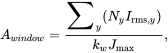 (9.3)
(9.3)
which shows that the window area is linearly proportional to the number of turns chosen by the designer.
9.4.2 Core Cross-Sectional Area Acore
The core cross-sectional area in Figures 9.1a and 9.1b depends on the peak flux ![]() and the choice of the maximal allowed flux density
and the choice of the maximal allowed flux density ![]() to limit core losses:
to limit core losses:
How the flux is produced depends on whether the device is an inductor or a transformer. In an inductor, ![]() depends on the peak current and equals the peak flux linkage
depends on the peak current and equals the peak flux linkage ![]() . Hence,
. Hence,
In a transformer, based on Faraday’s law, the flux depends linearly on the applied volt-seconds and inversely on the number of turns. This is shown in Figure 9.2 for a forward converter transformer with ![]() , and the duty ratio
, and the duty ratio ![]() , which is limited to 0.5. Therefore, we can express the peak flux in Figure 9.2 as
, which is limited to 0.5. Therefore, we can express the peak flux in Figure 9.2 as

FIGURE 9.2 Waveforms in a transformer for a forward converter..
where the factor ![]() equals
equals ![]() in a forward converter and typically has a maximum value of 0.5. The factor
in a forward converter and typically has a maximum value of 0.5. The factor ![]() can be derived for transformers in other converter topologies based on the specified operating conditions, for example, it equals
can be derived for transformers in other converter topologies based on the specified operating conditions, for example, it equals ![]() in a full-bridge converter. In general, the peak flux can be expressed in terms of any one of the windings,
in a full-bridge converter. In general, the peak flux can be expressed in terms of any one of the windings, ![]() , for example, as
, for example, as
Substituting for ![]() from Equations (9.5) and (9.7) into Equation (9.4), respectively, we find:
from Equations (9.5) and (9.7) into Equation (9.4), respectively, we find:
Equations (9.8) and (9.9) show that in both cases, the core cross-sectional area is inversely proportional to the number of turns chosen by the designer.
9.4.3 Core Area-Product 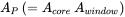
The core area-product is obtained by multiplying the core cross-sectional area ![]() with its window area
with its window area ![]() :
:
Substituting for ![]() and
and ![]() from the previous equations,
from the previous equations,
Equations (9.11) and (9.12) show that the area-product that represents the overall size of the device is independent (as it ought to be) of the number of turns. After all, the core and the overall component size should depend on the electrical specifications and the assumed values of ![]() and
and![]() and not on the number of turns, which is an internal design variable.
and not on the number of turns, which is an internal design variable.
9.4.4 Design Procedure Based on Area-Product Ap
Once we pick the appropriate material and the shape for a core, the cores by various manufacturers are cataloged based on the area-product ![]() . Having calculated the value of
. Having calculated the value of ![]() above, we can select the appropriate core. It should be noted that there are infinite combinations of the core cross-sectional area
above, we can select the appropriate core. It should be noted that there are infinite combinations of the core cross-sectional area ![]() and the window area
and the window area ![]() that yield the desired area-product
that yield the desired area-product ![]() . However, manufacturers take pains in producing cores such that for a given
. However, manufacturers take pains in producing cores such that for a given ![]() , a core has
, a core has ![]() and
and ![]() that are individually optimized for power density. Once we select a core, it has specific
that are individually optimized for power density. Once we select a core, it has specific ![]() and
and ![]() , which allow the number of turns to be calculated as follows:
, which allow the number of turns to be calculated as follows:
In an inductor, to ensure that it has the specified inductance, an air gap of an appropriate length ![]() is introduced in the path of flux lines. Assuming the chosen core material to have very high permeability, the core inductance is primarily dictated by the reluctance
is introduced in the path of flux lines. Assuming the chosen core material to have very high permeability, the core inductance is primarily dictated by the reluctance ![]() of the air gap, such that
of the air gap, such that
where
Using Equations (9.15) and (9.16), the air gap length ![]() can be calculated as:
can be calculated as:
The above equations are approximate because they ignore the effects of finite core permeability and the fringing flux, which can be substantial. Core manufacturers generally specify measured inductance as a function of the number of turns for various values of the air gap length. In this section, we used a toroidal core for descriptive purposes in which it will be difficult to introduce an air gap. If a toroidal core must be used, it can be picked with a distributed air gap such that it has the effective air gap length as calculated above. The above procedure explained for toroidal cores is equally valid for other types of cores. The actual design described in the next section illustrates the introduction of an air gap in a pot core.
9.5 DESIGN EXAMPLE OF AN INDUCTOR
In this example, we will discuss the design of an inductor that has an inductance ![]() . The worst-case current through the inductor is shown in Figure 9.3, where the average current
. The worst-case current through the inductor is shown in Figure 9.3, where the average current ![]() , and the peak-peak ripple
, and the peak-peak ripple ![]() at the switching frequency
at the switching frequency ![]() . We will assume the following maximum values for the flux density and the current density:
. We will assume the following maximum values for the flux density and the current density: ![]() , and
, and ![]() (for larger cores, this is typically in a range of 3 to
(for larger cores, this is typically in a range of 3 to ![]() ). The window fill factor is assumed to be
). The window fill factor is assumed to be ![]() .
.

FIGURE 9.3 Inductor current waveforms.
The peak value of the inductor current from Figure 9.3 is ![]() . The RMS value of the current for the waveform shown in Figure 9.3 can be calculated as
. The RMS value of the current for the waveform shown in Figure 9.3 can be calculated as ![]() (the derivation is left as a homework problem).
(the derivation is left as a homework problem).
From Equation (9.11),
From the Magnetics, Inc. catalog [2], we will select a p-type material that has a saturation flux density of ![]() and is quite suitable for use at the switching frequency of
and is quite suitable for use at the switching frequency of ![]() . A pot core 26 × 16, which is shown in Figure 9.4 for a laboratory experiment, has the core Area
. A pot core 26 × 16, which is shown in Figure 9.4 for a laboratory experiment, has the core Area ![]() and the window Area
and the window Area ![]() . Therefore, we will select this core, which has an Area-Product
. Therefore, we will select this core, which has an Area-Product ![]() . From Equation (9.13),
. From Equation (9.13),

FIGURE 9.4 Pot core mounted on a plug-in board.
Winding wire cross-sectional area ![]() . We will use five strands of American Wire Gauge AWG 25 wires [3], each with a cross-sectional area of 0.16 mm2, in parallel. From Equation (9.17), the air gap length can be calculated as
. We will use five strands of American Wire Gauge AWG 25 wires [3], each with a cross-sectional area of 0.16 mm2, in parallel. From Equation (9.17), the air gap length can be calculated as
9.6 DESIGN EXAMPLE OF A TRANSFORMER FOR A FORWARD CONVERTER
The required electrical specifications for the transformer in a forward converter are as follows: ![]() and
and ![]() . Assume the RMS value of the current in each winding to be
. Assume the RMS value of the current in each winding to be ![]() . We will choose the following values for this design:
. We will choose the following values for this design: ![]() and
and ![]() . From Equation (9.12), where
. From Equation (9.12), where ![]() and
and![]() ,
,
For the pot core 22 × 13 [2], ![]() ,
, ![]() , and therefore
, and therefore ![]() . For this core, the winding wire cross-sectional area is obtained as
. For this core, the winding wire cross-sectional area is obtained as
We will use three strands of AWG 25 wires [3], each with a cross-sectional area of ![]() , in parallel for each winding. From Equation (9.14),
, in parallel for each winding. From Equation (9.14),
Hence,
9.7 THERMAL CONSIDERATIONS
Designs presented here do not include eddy current losses in the windings, which can be very substantial due to proximity effects. These proximity losses in a conductor are due to the high-frequency magnetic field generated by other conductors in close proximity. These proximity losses can be minimized by designing inductors with a single-layer construction. In transformers, windings can be interleaved to minimize these losses, as described in detail in [1]. Therefore, the area-product method discussed in this chapter is a good starting point, but the designs must be evaluated for the temperature rise due to additional losses. A more detailed analysis is presented in [4].
REFERENCES
- 1. N. Mohan, T.M. Undeland, and W.P. Robbins, Power Electronics: Converters, Applications and Design, 3rd Edition (New York: John Wiley & Sons, 2003).
- 2. Magnetics, Inc. Ferrite Cores: www.mag-inc.com.
- 3. Wire Gauge Comparison Chart: http://www.engineeringtoolbox.com/wire-gauges-d_419.html.
- 4. N. Mohan, W. Robins, T. Undeland, and S. Raju, Power Electronics for Grid-Integration of Renewables: Analysis, Simulations and Hardware Lab (New York: John Wiley & Sons, 2023).
PROBLEMS
Inductor Design
- 9.1 Derive the expression for the RMS current for the current waveform in Figure 9.3.
- 9.2 In the design example of the inductor in Section 9.5 of this chapter, the core has an area
 , the mean magnetic path length
  , and the relative permeability of the core material is
  . Calculate the inductance with 23 turns if the air gap is not introduced in this core in the flux path.
 - 9.3 In the inductor design presented in Section 9.5 of this chapter, what is the reluctance offered by the magnetic core as compared to that offered by the air gap if the mean magnetic path length of the core is
 ?
? - 9.4 In Problem 9.2, what is the maximum current that will cause the peak flux density to reach
 ?
? - 9.5 In the inductor designed in Section 9.5 of this chapter, what will be the inductance and the maximum current that can be passed without exceeding the
 specified, if the air gap introduced by mistake is only one-half of the required value?
Transformer Design
- 9.6 In the design example of the transformer in Section 9.6 of this chapter, the core has an area
 , the magnetic path
  , and the relative permeability of the core material is
  . Calculate the peak magnetizing current at duty ratio of 0.5 in this example.
 - 9.7 What is the tertiary winding conductor diameter needed for the magnetizing current calculated in Problem 9.6?
- 9.8 Derive
 for transformers in two-switch forward, half-bridge, and push-pull converters.