
11
APPLICATIONS OF SWITCH-MODE POWER ELECTRONICS IN MOTOR DRIVES, UNINTERRUPTIBLE POWER SUPPLIES, AND POWER SYSTEMS
11.1 INTRODUCTION
Electric motor drives (AC and DC), uninterruptible power supplies (UPS), and power systems are major application areas of switch-mode power electronics. In these applications, the role of power electronics converters is to synthesize appropriate voltages of desirable amplitude, frequency, phase, and the number of phases, where the power flow is often bidirectional. This synthesis process is described in detail in the next chapter. The purpose of this chapter is to present various applications and describe the voltage and current requirements they impose on the power electronics converters.
11.2 ELECTRIC MOTOR DRIVES
As described in Chapter 1, motor drives represent an important application area of power electronics with a market value of tens of billions of dollars annually. Figure 11.1 shows the block diagram of an electric motor drive, or for short, an electric drive. In response to an input command, electric drives efficiently control the speed and the position of the mechanical load. The controller, by comparing the input command for speed and position with the actual values measured through sensors, provides appropriate control signals to the power-processing unit (PPU) consisting of power semiconductor devices.
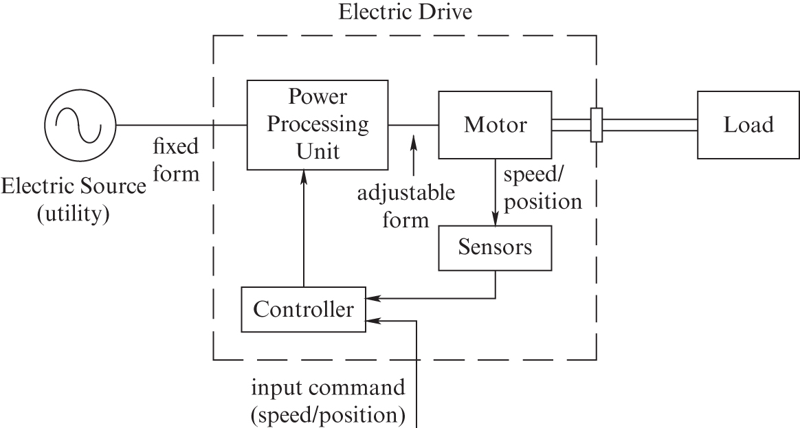
FIGURE 11.1 Block diagram of an electric drive system [1].
As Figure 11.1 shows, the power-processing unit gets its power from the utility source with single-phase or three-phase sinusoidal voltages of a fixed frequency and constant amplitude. The power-processing unit, in response to the control inputs, efficiently converts these fixed-form input voltages into an output of the appropriate form (in frequency, amplitude, and number of phases) that is optimally suited for operating the motor. The input command to the electric drive in Figure 11.1 may come from a process computer, which considers the objectives of the overall process and issues a command to control the mechanical load. However, in general-purpose applications, electric drives operate in an open-loop manner without any feedback.
We will briefly examine various types of electric machines in terms of their terminal characteristics in steady state in order to determine the voltage and current ratings in designing the power electronics interface.
11.2.1 DC Motors
DC motors were widely used in the past for all types of drive applications, and they continue to be used for controlling speed and position. There are two designs of DC machines: stators consisting of either permanent magnets or a field winding. The power-processing units can also be classified into two categories, either switch-mode power converters that operate at a high switching frequency, as discussed in the next chapter, or line-commutated thyristor converters, which are discussed later, in Chapter 14. In this chapter, we will describe permanent-magnet DC motors, which are usually supplied by switch-mode power electronic converters.
Figure 11.2 shows a cut-away view of a DC motor. It shows a permanent-magnet stator, a rotor that carries a winding, a commutator, and the brushes. In DC machines, the stator establishes a uniform flux ![]() in the air gap in the radial direction (the subscript “f” is for field). If permanent magnets like those shown in Figure 11.2 are used, the air gap flux density established by the stator remains constant. A field winding whose current can be varied can be used to achieve an additional degree of control over the air gap flux density.
in the air gap in the radial direction (the subscript “f” is for field). If permanent magnets like those shown in Figure 11.2 are used, the air gap flux density established by the stator remains constant. A field winding whose current can be varied can be used to achieve an additional degree of control over the air gap flux density.

FIGURE 11.2 Exploded view of a DC motor. Source: Electro-Craft Corporation.
As shown in Figure 11.2, the rotor slots contain a winding, called the armature winding, which handles electrical power for conversion to (or from) mechanical power at the rotor shaft. In addition, there is a commutator affixed to the rotor. On its outer surface, the commutator contains copper segments, which are electrically insulated from each other by means of mica or plastic. The coils of the armature winding are connected to these commutator segments so that a stationary DC source can supply voltage and current to the rotating commutator by means of stationary carbon brushes that rest on top of the commutator. The wear due to the mechanical contact between the commutator and the brushes requires periodic maintenance, which is the main drawback of DC machines.
In a DC machine, the magnitude and the direction of the electromagnetic torque depend on the armature current ![]() . Therefore, in a permanent-magnet DC machine, the electromagnetic torque produced by the machine is linearly related to a machine torque constant
. Therefore, in a permanent-magnet DC machine, the electromagnetic torque produced by the machine is linearly related to a machine torque constant ![]() , which is unique to a given machine and is specified in its data sheets,
, which is unique to a given machine and is specified in its data sheets,
Similarly, the induced emf ![]() depends only on the rotational speed
depends only on the rotational speed ![]() , and can be related to it by a voltage constant
, and can be related to it by a voltage constant ![]() , which is unique to a given machine and specified in its data sheets,
, which is unique to a given machine and specified in its data sheets,
Equating the mechanical power (![]() ) to the electrical power (
) to the electrical power (![]() ), the torque constant
), the torque constant ![]() and the voltage constant
and the voltage constant ![]() are exactly the same numerically in MKS units,
are exactly the same numerically in MKS units,
The direction of the armature current ![]() determines the direction of currents through the conductors. Therefore, the direction of the electromagnetic torque produced by the machine also depends on the direction of
determines the direction of currents through the conductors. Therefore, the direction of the electromagnetic torque produced by the machine also depends on the direction of ![]() . This explains how a DC machine, while rotating in a forward or reverse direction, can be made to go from motoring mode (where the speed and torque are in the same direction) to its generator mode (where the speed and torque are in the opposite direction) by reversing the direction of
. This explains how a DC machine, while rotating in a forward or reverse direction, can be made to go from motoring mode (where the speed and torque are in the same direction) to its generator mode (where the speed and torque are in the opposite direction) by reversing the direction of ![]()
Applying a reverse-polarity DC voltage to the armature terminals makes the armature current flow in the opposite direction. Therefore, the electromagnetic torque is reversed, after some time reversing the direction of rotation and the polarity of induced emfs in conductors, which depends on the direction of rotation.
The above discussion shows that a DC machine can easily be made to operate as a motor or as a generator in the forward or in the reverse direction of rotation.
It is convenient to discuss a DC machine in terms of its equivalent circuit, presented in Figure 11.3, which shows the conversion between electrical and mechanical power. The armature current ![]() produces the electromagnetic torque
produces the electromagnetic torque ![]() necessary to rotate the mechanical load at the desired speed. Across the armature terminals, the rotation at the speed of
necessary to rotate the mechanical load at the desired speed. Across the armature terminals, the rotation at the speed of ![]() induces a voltage, called the back-emf
induces a voltage, called the back-emf ![]() , represented by a dependent voltage source.
, represented by a dependent voltage source.

FIGURE 11.3 DC motor equivalent circuit.
The applied voltage ![]() from the PPU overcomes the back-emf
from the PPU overcomes the back-emf ![]() and causes the current
and causes the current ![]() to flow. Recognizing that there is a voltage drop across both the armature winding resistance
to flow. Recognizing that there is a voltage drop across both the armature winding resistance ![]() (which includes the voltage drop across the carbon brushes) and the armature winding inductance
(which includes the voltage drop across the carbon brushes) and the armature winding inductance ![]() , we can write the equation of the electrical side as
, we can write the equation of the electrical side as
On the mechanical side, the electromagnetic torque produced by the motor overcomes the mechanical-load torque ![]() to produce acceleration:
to produce acceleration:
where ![]() is the total effective value of the combined inertia of the DC machine and the mechanical load.
is the total effective value of the combined inertia of the DC machine and the mechanical load.
Note that the electric and the mechanical systems are coupled. The torque ![]() in the mechanical system (Equation 11.1) depends on the electrical current
in the mechanical system (Equation 11.1) depends on the electrical current ![]() The back-emf
The back-emf ![]() in the electrical system (Equation 11.2) depends on the mechanical speed
in the electrical system (Equation 11.2) depends on the mechanical speed ![]() . The electrical power absorbed from the electrical source by the motor is converted into mechanical power and vice versa. In a DC steady state, with a voltage
. The electrical power absorbed from the electrical source by the motor is converted into mechanical power and vice versa. In a DC steady state, with a voltage ![]() applied to the armature terminals and a load torque
applied to the armature terminals and a load torque ![]() being supplied to the load, the inductance
being supplied to the load, the inductance ![]() in the equivalent circuit of Figure 11.3 does not play a role. Hence, in Figure 11.3,
in the equivalent circuit of Figure 11.3 does not play a role. Hence, in Figure 11.3,
11.2.1.1 Requirements Imposed by DC Machines on the PPU
Based on Equations 11.6 and 11.7, the steady-state torque-speed characteristics for various values of ![]() are plotted in Figure 11.4a. Neglecting the voltage drop across the armature resistance in Equation 11.7, the terminal voltage
are plotted in Figure 11.4a. Neglecting the voltage drop across the armature resistance in Equation 11.7, the terminal voltage ![]() varies linearly with the speed
varies linearly with the speed ![]() , as plotted in Figure 11.4b. At low values of speed, the voltage drop across the armature resistance can be a significant component of the terminal voltage, and hence the relationship in Figure 11.4a in this region is shown dotted.
, as plotted in Figure 11.4b. At low values of speed, the voltage drop across the armature resistance can be a significant component of the terminal voltage, and hence the relationship in Figure 11.4a in this region is shown dotted.

FIGURE 11.4 (a) Torque-speed characteristics, and (b)  versus
  .
.
In summary, in DC-motor drives, the voltage rating of the power-processing unit is dictated by the maximum speed, and the current rating is dictated by the maximum load torque being supplied.
11.2.2 Permanent-Magnet AC Machines
Sinusoidal-waveform, permanent-magnet AC (PMAC) drives are used in applications where high efficiency and high power density are required in controlling the speed and position. In trade literature, they are also called “brushless DC” drives. We will examine these machines for speed and position control applications, usually in small (<10 kW) power ratings, where these drives have three-phase AC stator windings, and the rotor has DC excitation in the form of permanent magnets. In such drives, the stator windings of the machine are supplied by controlled currents, which require a closed-loop operation, as described later in this section.
We will consider 2-pole machines, like the one shown schematically in Figure 11.5a. This analysis can be generalized to p-pole machines where ![]() . The stator contains three-phase, wye-connected windings, each of which produces a sinusoidally distributed flux-density distribution in the air gap when supplied by a current.
. The stator contains three-phase, wye-connected windings, each of which produces a sinusoidally distributed flux-density distribution in the air gap when supplied by a current.
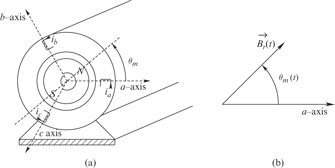
FIGURE 11.5 Two-pole PMAC machine.
The permanent-magnet pole pieces mounted on the rotor surface are shaped to ideally produce a sinusoidally distributed flux density in the air gap. The rotor flux-density distribution (represented by a vector ![]() ) peaks at an axis that is at an angle
) peaks at an axis that is at an angle ![]() with respect to the a-axis (the phase axis of winding a), as shown in Figure 11.5b. As the rotor turns, the entire rotor-produced flux density distribution in the air gap rotates with it and “cuts” the stator-winding conductors and produces emf in phase windings that are sinusoidal functions of time. In the AC steady state, these voltages can be represented by phasors.
with respect to the a-axis (the phase axis of winding a), as shown in Figure 11.5b. As the rotor turns, the entire rotor-produced flux density distribution in the air gap rotates with it and “cuts” the stator-winding conductors and produces emf in phase windings that are sinusoidal functions of time. In the AC steady state, these voltages can be represented by phasors.
Considering phase-a as the reference in Figure 11.5b, the induced voltage in it due to the rotor flux cutting it can be expressed as
It should be noted that by Faraday’s law (![]() , where
, where ![]() is the flux-linkage of the coil), the induced voltage in phase-a peaks when the rotor-flux peak in Figure 11.5a is pointing downward,
is the flux-linkage of the coil), the induced voltage in phase-a peaks when the rotor-flux peak in Figure 11.5a is pointing downward, ![]() before it reaches the phase-a magnetic axis. Since the permanent magnets on the rotor produce a constant amplitude flux, the RMS magnitude of the induced voltage in each stator phase is linearly related to the rotational speed
before it reaches the phase-a magnetic axis. Since the permanent magnets on the rotor produce a constant amplitude flux, the RMS magnitude of the induced voltage in each stator phase is linearly related to the rotational speed ![]() by a per-phase voltage-constant
by a per-phase voltage-constant ![]() ,
,
An important characteristic of the machines under consideration is that they are supplied through a current-regulated power-processing unit, which controls the currents ![]() ,
, ![]() , and
, and ![]() supplied to the stator at any instant of time. To optimize such that the maximum torque-per-ampere is produced, each phase current in AC steady-state is controlled in phase with the induced voltage. Therefore, with the voltage expressed in Equation 11.8, the current in AC steady state is
supplied to the stator at any instant of time. To optimize such that the maximum torque-per-ampere is produced, each phase current in AC steady-state is controlled in phase with the induced voltage. Therefore, with the voltage expressed in Equation 11.8, the current in AC steady state is
In AC steady state, accounting for all three phases, the input electric power, supplied by the current in opposition to the induced back-emf, equals the mechanical output power. Using Equations 11.8 through 11.10,
The torque contribution of each phase is ![]() , so from Equation 11.11,
, so from Equation 11.11,
where the constant that relates the RMS current to the per-phase torque is the per-phase torque constant ![]() and similar to that in DC machines, in MKS units,
and similar to that in DC machines, in MKS units,
At this point, we should note that PMAC drives constitute a class, which we will call self-synchronous motor drives, where the term “self” is added to distinguish these machines from the conventional synchronous machines. The reason for this is as follows: in PMAC drives, the stator phase currents are synchronized to the mechanical position of the rotor such that, for example, the current into phase-a, in order to be in phase with the induced emf, peaks when the rotor-flux peak is pointing downward, ![]() before it reaches the phase-a magnetic axis. This explains the necessity for the rotor-position sensor, as shown in the block diagram of such drives in Figure 11.6.
before it reaches the phase-a magnetic axis. This explains the necessity for the rotor-position sensor, as shown in the block diagram of such drives in Figure 11.6.

FIGURE 11.6 Block diagram of a PMAC machine.
As shown in the block diagram of Figure 11.6, the task of the controller is to enable the power-processing unit to supply the desired currents to the PMAC motors. The reference torque signal is generated from the outer speed and position loops. The rotor position ![]() is measured by the position sensor connected to the shaft. Knowing the torque constant
is measured by the position sensor connected to the shaft. Knowing the torque constant ![]() allows us to calculate the RMS value of the reference current from Equation 11.12. Knowing the current RMS value and
allows us to calculate the RMS value of the reference current from Equation 11.12. Knowing the current RMS value and ![]() allows the reference currents
allows the reference currents ![]() ,
, ![]() , and
, and ![]() for the three phases to be calculated, which the PPU delivers at any instant of time.
for the three phases to be calculated, which the PPU delivers at any instant of time.
The electromagnetic torque acts on the mechanical system connected to the rotor, and the resulting speed ![]() can be obtained from the equation below:
can be obtained from the equation below:
where ![]() is the combined motor-load inertia and
is the combined motor-load inertia and ![]() is the load torque, which may include friction. The rotor position
is the load torque, which may include friction. The rotor position ![]() is
is
 (11.15)
where ![]() is the rotor position at time t = 0. Similar to a DC machine, it is convenient to discuss a PMAC machine in terms of its equivalent circuit of Figure 11.7, which shows the conversion between electrical and mechanical power.
is the rotor position at time t = 0. Similar to a DC machine, it is convenient to discuss a PMAC machine in terms of its equivalent circuit of Figure 11.7, which shows the conversion between electrical and mechanical power.
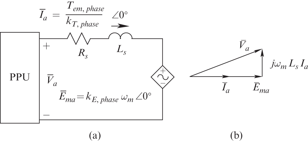
FIGURE 11.7 Equivalent circuit diagram and the phasor diagram of PMAC (2-pole).
In the AC steady state, using phasors, the current ![]() is ensured by the feedback control to be in phase with the phase-a induced voltage
is ensured by the feedback control to be in phase with the phase-a induced voltage ![]() . The phase currents produce the total electromagnetic torque necessary to rotate the mechanical load at a speed
. The phase currents produce the total electromagnetic torque necessary to rotate the mechanical load at a speed ![]() . The induced back-emf
. The induced back-emf ![]() , whose RMS magnitude is linearly proportional to the speed of rotation
, whose RMS magnitude is linearly proportional to the speed of rotation ![]() , is represented by a dependent voltage source.
, is represented by a dependent voltage source.
The applied voltage ![]() in Figure 11.7a overcomes the back-emf
in Figure 11.7a overcomes the back-emf ![]() and causes the current
and causes the current ![]() to flow. The frequency of the phasors in hertz equals
to flow. The frequency of the phasors in hertz equals ![]() in a 2-pole PMAC machine. There is a voltage drop across both the per-phase stator winding resistance
in a 2-pole PMAC machine. There is a voltage drop across both the per-phase stator winding resistance ![]() (neglected here) and a per-phase inductance
(neglected here) and a per-phase inductance ![]() , which is the sum of the leakage inductance
, which is the sum of the leakage inductance ![]() caused by the leakage flux of the stator winding and
caused by the leakage flux of the stator winding and ![]() due to the effect of the combined flux produced by the currents flowing in the stator phases. The phasor diagram, neglecting
due to the effect of the combined flux produced by the currents flowing in the stator phases. The phasor diagram, neglecting ![]() , is shown in Figure 11.7b.
, is shown in Figure 11.7b.
11.2.2.1 Requirements Imposed by PMAC Machines on the PPU
In PMAC machines, the speed is independent of the electromagnetic torque developed by the machine, as shown in Figure 11.8a, and depends on the frequency of voltages and currents applied to the stator phases of the machine.
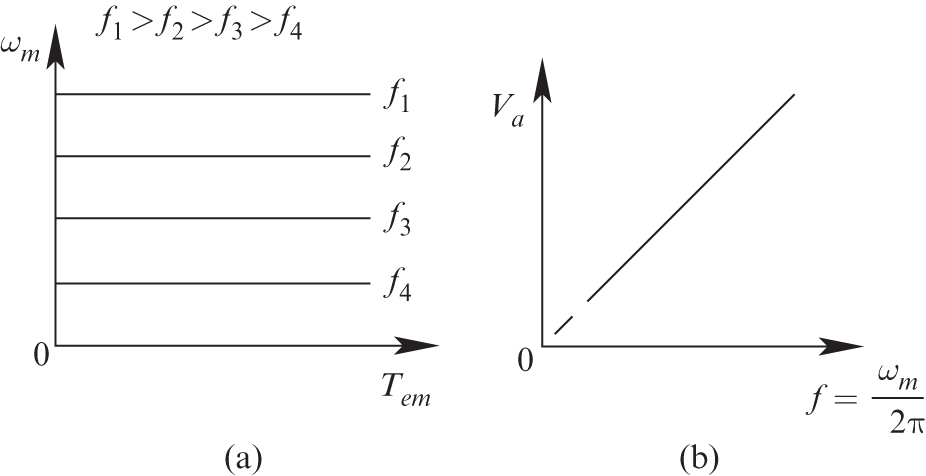
FIGURE 11.8 Torque-speed characteristics and voltage versus frequency in PMAC.
In the per-phase equivalent circuit of Figure 11.7a and the phasor diagram of Figure 11.7b, the back-emf is proportional to the speed ![]() Similarly, since the electrical frequency is linearly related to
Similarly, since the electrical frequency is linearly related to ![]() the voltage drop across
the voltage drop across ![]() is also proportional to
is also proportional to ![]() . Therefore, neglecting the per-phase stator winding resistance
. Therefore, neglecting the per-phase stator winding resistance ![]() , in the phasor diagram of Figure 11.7b, the voltage phasors are all proportional to
, in the phasor diagram of Figure 11.7b, the voltage phasors are all proportional to ![]() , requiring that the per-phase voltage magnitude that the power-processing unit needs to supply is proportional to the speed
, requiring that the per-phase voltage magnitude that the power-processing unit needs to supply is proportional to the speed ![]() as plotted in Figure 11.8b.
as plotted in Figure 11.8b.
At very low speeds, this voltage-speed relationship, shown dotted in Figure 11.8b, is approximate, where a higher voltage, called the voltage boost, is needed to overcome the voltage drop across the stator winding resistance ![]() ; this voltage drop becomes significant at higher torque loading and hence cannot be neglected.
; this voltage drop becomes significant at higher torque loading and hence cannot be neglected.
In summary, in PMAC-motor drives, similar to DC drives, the voltage rating of the power-processing unit is dictated by the maximum speed, and the current rating is dictated by the maximum load torque being supplied.
11.2.3 Induction Machines
Induction motors with squirrel-cage rotors are the workhorses of industry because of their low cost and rugged construction. When operated directly from line voltages (a 50- or 60-Hz utility input at essentially a constant voltage), induction motors operate at a nearly constant speed. However, by means of power electronic converters, it is possible to vary their speed efficiently.
Just as in PMAC motors, the stator of an induction motor consists of three-phase windings distributed in the stator slots. These three windings are displaced by 120° in space with respect to each other, as shown by their axes in Figure 11.9a.

FIGURE 11.9 (a) Three-phase stator; (b) squirrel-cage rotor.
The rotor, consisting of a stack of insulated laminations, has electrically conducting bars of copper or aluminum inserted (molded) through it, close to the periphery in the axial direction. These bars are electrically shorted at each end of the rotor by electrically conducting end-rings, thus producing a conducting cage-like structure, as shown in Figure 11.9b. Such a rotor, called a squirrel-cage rotor, has a low cost and rugged nature.
Figure 11.10a shows the stator windings whose voltages are shown in the phasor diagram of Figure 11.10b, where the frequency of the applied line voltages to the motor is ![]() in hertz, and
in hertz, and ![]() is the magnitude in RMS.
is the magnitude in RMS.

FIGURE 11.10 Induction machine: applied voltages and magnetizing currents.
By Faraday’s law, the applied stator voltages given in Equation 11.16 establish a rotating flux-density distribution in the air gap by drawing magnetizing currents of RMS value ![]() , which are shown in Figure 11.10b:
, which are shown in Figure 11.10b:
As these currents vary sinusoidally with time, the combined flux-density distribution in the air gap, produced by these currents, rotates with a constant amplitude at a synchronous speed ![]() , where
, where
The rotor in an induction motor turns (due to the electromagnetic torque developed, as will be discussed shortly) at a speed ![]() in the same direction as the rotation of the air gap flux-density distribution, such that
in the same direction as the rotation of the air gap flux-density distribution, such that ![]() . Therefore, there is a relative speed between the flux-density distribution rotating at
. Therefore, there is a relative speed between the flux-density distribution rotating at ![]() and the rotor conductors at
and the rotor conductors at ![]() . This relative speed, that is, the speed at which the rotor is “slipping” with respect to the rotating flux-density distribution, is called the slip speed:
. This relative speed, that is, the speed at which the rotor is “slipping” with respect to the rotating flux-density distribution, is called the slip speed:
By Faraday’s law ![]() , voltages are induced in the rotor bars at the slip frequency due to the relative motion between the flux-density distribution and the rotor, where the slip frequency
, voltages are induced in the rotor bars at the slip frequency due to the relative motion between the flux-density distribution and the rotor, where the slip frequency ![]() in terms of the frequency
in terms of the frequency ![]() of the stator voltages and currents is
of the stator voltages and currents is
Since the rotor bars are shorted at both ends, these induced bar voltages cause slip-frequency currents to flow in the rotor bars. The rotor-bar currents interact with the flux-density distribution established by the stator-applied voltages, and the result is a net electromagnetic torque ![]() in the same direction as the rotor’s rotation.
in the same direction as the rotor’s rotation.
The sequence of events in an induction machine to meet the load torque demand is as follows: At essentially no load, an induction machine operates nearly at the synchronous speed that depends on the frequency of applied stator voltages (Equation 11.18). As the load torque increases, the motor slows down, resulting in a higher value of slip speed. Higher slip speed results in higher voltages induced in the rotor bars and hence higher rotor-bar currents. Higher rotor-bar currents result in a higher electromagnetic torque to satisfy the increased load-torque demand.
Neglecting second-order effects, the air gap flux is totally determined by the applied stator voltages. Hence, the air gap flux produced by the rotor-bar currents is nullified by the additional currents drawn by the stator windings, which are in addition to the magnetizing currents in Equation 11.17.
In this balanced three-phase sinusoidal steady-state analysis, we will neglect second-order effects such as the stator winding resistance and leakage inductance and the rotor circuit leakage inductance. As shown in Figure 11.11a for phase-a in this per-phase circuit, ![]() and, similarly for the other two phases, are applied at a frequency
and, similarly for the other two phases, are applied at a frequency ![]() , which results in magnetizing currents to establish the air gap flux-density distribution in the air gap.
, which results in magnetizing currents to establish the air gap flux-density distribution in the air gap.

FIGURE 11.11 Induction motor equivalent circuit and phasor diagram.
These magnetizing currents are represented as flowing through a magnetizing inductance ![]() . The voltage magnitude and the frequency are such that the magnitude of the flux-density distribution in the air gap is at its rated value, and this distribution rotates counterclockwise at the desired
. The voltage magnitude and the frequency are such that the magnitude of the flux-density distribution in the air gap is at its rated value, and this distribution rotates counterclockwise at the desired ![]() (Equation 11.18) to induce a back-emf in the stationary stator phase windings such that
(Equation 11.18) to induce a back-emf in the stationary stator phase windings such that
where ![]() is the machine per-phase voltage-constant.
is the machine per-phase voltage-constant.
Next, we will consider the effect of the rotor-bar currents. The rotor-bar currents result in additional stator currents (in addition to the magnetizing current), which can be represented on a per-phase basis by a current ![]() in-phase with the applied voltage (since the rotor-circuit leakage inductance is ignored), as shown in Figure 11.11a,
in-phase with the applied voltage (since the rotor-circuit leakage inductance is ignored), as shown in Figure 11.11a,
Note that the torque on the stator is equal in magnitude and opposite in direction to the torque on the rotor. The flux-density distribution (although produced differently than in PMAC machines) interacts with these stator currents, just like in PMAC machines, and hence the per-phase torque constant equals the per-phase voltage constant,
The per-phase torque can be expressed as
This torque at a mechanical speed ![]() results in per-phase electromagnetic power that gets converted to mechanical power, where using Equations 11.23 and 11.24,
results in per-phase electromagnetic power that gets converted to mechanical power, where using Equations 11.23 and 11.24,
In Equation 11.25, ![]() can be considered the back-emf
can be considered the back-emf ![]() , just like in the DC and the PMAC machines, as shown in Figure 11.11a,
, just like in the DC and the PMAC machines, as shown in Figure 11.11a,
In the rotor circuit, the voltages induced depend on the slip speed ![]() and overcome the IR voltage drop in the rotor bar resistances. The rotor bar resistances, the voltage drop, and the power losses in them are represented in the per-phase equivalent circuit of Figure 11.11a by a voltage drop across an equivalent resistance
and overcome the IR voltage drop in the rotor bar resistances. The rotor bar resistances, the voltage drop, and the power losses in them are represented in the per-phase equivalent circuit of Figure 11.11a by a voltage drop across an equivalent resistance ![]() . Using Kirchhoff’s voltage law in Figure 11.11a,
. Using Kirchhoff’s voltage law in Figure 11.11a,
Hence,
Using Equations 11.23, 11.25, and 11.28, the combined torque of all three phases is
 (11.29)
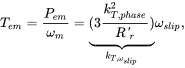
where ![]() in the above equation is a machine constant that shows that the torque produced is linearly proportional to the slip speed. Using Equations 11.19 and 11.29,
in the above equation is a machine constant that shows that the torque produced is linearly proportional to the slip speed. Using Equations 11.19 and 11.29,
11.2.3.1 Requirements Imposed by Induction Machines on the PPU
Based on Equation 11.30, the torque-speed characteristics are shown in Figure 11.12 for various applied frequencies to the stator. Based on Equation 11.21, the stator voltage as a function of frequency is shown in Figure 11.13 to maintain the peak of the flux-density distribution at its rated value. The relationship between the voltage and the synchronous speed or ![]() shown in Figure 11.13, is approximate. A substantially higher voltage than indicated (shown dotted) is needed at very low frequencies where the voltage drop across the stator winding resistance
shown in Figure 11.13, is approximate. A substantially higher voltage than indicated (shown dotted) is needed at very low frequencies where the voltage drop across the stator winding resistance ![]() becomes substantial at higher torque loading and hence cannot be neglected.
becomes substantial at higher torque loading and hence cannot be neglected.
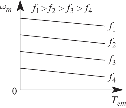
FIGURE 11.12 Induction motor torque-speed characteristics
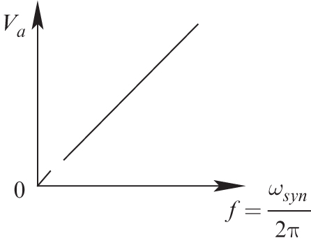
FIGURE 11.13 Induction motor voltage vs frequency
In summary, in induction motor drives, similar to DC and PMAC drives, the voltage rating of the power-processing unit is dictated by the maximum speed, and the current rating is dictated by the maximum load torque being supplied.
11.3 UNINTERRUPTIBLE POWER SUPPLIES (UPS)
Uninterruptible power supplies (UPS) are used to provide power to critical loads in industry, business, and medical facilities, to which power should be available continuously, even during momentary utility power outages. The Computer Business Equipment Manufacturers Association (CBEMA) has specifications that show the voltage tolerance envelope as a function of time. The ITI-CBEMA curve shows that the UPS for critical loads is needed, not just for complete power outages but also for “swells” and “sags” in the equipment voltage due to disturbances on the utility grid. In considering the synthesis of a low-frequency AC from a DC voltage, UPS can be considered as a special case of AC motor drives.
In a UPS, storage means, generally a battery bank, is used to shield critical loads from voltage disturbances, as shown in the block diagram of Figure 11.14.

FIGURE 11.14 Block diagram of UPS.
Therefore, there is an intermediate DC link. Normally, the power to the load is provided through the two converters, where the utility-side converter also keeps the batteries charged. In the event of power-line outages, energy stored in the batteries allows load power to be supplied continuously. The function of the load-side inverter is to produce, from the DC source, AC voltages similar to that in AC motor drives, except it is a special case where the output voltage has a constant specified magnitude and frequency (e.g., 115 V RMS, and 60 Hz). The load may be single-phase or three-phase. The voltage and current ratings of the UPS converters are dictated by the load that is being supplied.
11.4 UTILITY APPLICATIONS OF SWITCH-MODE POWER ELECTRONICS
Thyristor-based applications of power electronics in utility systems are well established in the form of HVDC transmission, excitation control of generators, switched capacitors for static var control, and so on. In addition to these applications based on thyristor converters discussed in Chapter 14, there are growing applications of switch-mode power electronics. These include voltage-link HVDC systems, discussed in Chapter 14, and static compensators (STATCOM) for var control. Other applications include series-voltage injection for controlling the flow of power and for compensating voltage sags and swells beyond the limits specified by the CBEMA curve of Figure 11.13.
All the above applications of switch-mode power electronics are based on the fact that in a switched-mode converter, shown in Figure 11.15 as a block diagram with the DC voltage at one side forming the voltage port, a voltage of appropriate amplitude, frequency, and phase can be synthesized at the current port. This converter can have single- or three-phase outputs, and the power flow can be bidirectional. The utility system is shown at the right with a voltage ![]() .
.

FIGURE 11.15 Interaction of the switch-mode converter with the AC utility system.
The per-phase AC side is shown in Figure 11.16a by means of the fundamental-frequency quantities, where ![]() is the voltage synthesized by the converter, and
is the voltage synthesized by the converter, and ![]() is the utility voltage. These two AC voltage sources of the same frequency are connected through a reactance
is the utility voltage. These two AC voltage sources of the same frequency are connected through a reactance ![]() in series. The phasor diagram for the variables in Figure 11.16a is shown in Figure 11.16b.
in series. The phasor diagram for the variables in Figure 11.16a is shown in Figure 11.16b.

FIGURE 11.16 Per-phase equivalent circuit and the phasor diagram.
The following discussion shows that the real power ![]() flows “downhill” on the phase angles of the voltages, and not their magnitudes, whereas the reactive power Q flows based on the magnitudes of the two voltages.
flows “downhill” on the phase angles of the voltages, and not their magnitudes, whereas the reactive power Q flows based on the magnitudes of the two voltages.
In the circuit of Figure 11.16a,
At the utility end, the complex power can be written as
Using the complex conjugate from Equation 11.31 into Equation 11.32, and selecting the utility voltage as the reference phasor ![]() where
where ![]() ,
,
which is the same as the sending end power ![]() assuming no transmission-line losses. And
assuming no transmission-line losses. And
If the power transfer from the converter to the utility system is zero, then, from Equation 11.34, ![]() and, hence the angle
and, hence the angle ![]() is equal to zero. Under this condition, from Equation 11.35,
is equal to zero. Under this condition, from Equation 11.35,
where the reactive power is supplied by the converter, as if it were a capacitor, to the utility system.
Equations 11.34 and 11.35 together show that by controlling ![]() , in amplitude and phase, it is possible to control both the real and the reactive powers, as shown by the circular trajectories of voltage and current phasors in Figure 11.16b. This is what’s done in HVDC systems. Equation 11.36 shows that when the real power transfer is zero (
, in amplitude and phase, it is possible to control both the real and the reactive powers, as shown by the circular trajectories of voltage and current phasors in Figure 11.16b. This is what’s done in HVDC systems. Equation 11.36 shows that when the real power transfer is zero (![]() ), by controlling the amplitude
), by controlling the amplitude ![]() in comparison to the utility-grid voltage magnitude, it is possible to control
in comparison to the utility-grid voltage magnitude, it is possible to control ![]() in magnitude and polarity, that is, supply vars to the utility grid as a shunt-connected capacitor would or absorb it from the utility grid as a shunt-connected inductor would. This is what’s done in static var compensators (STATCOM). These applications, such as HVDC and STATCOM, are further discussed in Chapter 14.
in magnitude and polarity, that is, supply vars to the utility grid as a shunt-connected capacitor would or absorb it from the utility grid as a shunt-connected inductor would. This is what’s done in static var compensators (STATCOM). These applications, such as HVDC and STATCOM, are further discussed in Chapter 14.
REFERENCE
- 1. N. Mohan, Electric Drives: An Integrative Approach (New York: John Wiley & Sons, 2011).
PROBLEMS
Mechanical Systems
- 11.1 A constant torque of 5 Nm is applied to an unloaded motor at rest at time t = 0. The motor reaches a speed of 1800 rpm in 5 s. Assuming the damping to be negligible, calculate the motor inertia.
- 11.2 In an electric motor drive, the combined motor-load inertia is
 The load torque is
  . Plot the electromagnetic torque required from the motor to bring the system linearly from rest to a speed of 100 rad/s in 5 s and then maintain that speed.
 - 11.3 Calculate the power required in Problem 11.2.
DC Motors
- 11.4 A permanent-magnet DC motor has the following parameters:
 and
and  in MKS units. For a torque of up to 10 Nm, plot its steady-state torque-speed characteristics for the following values of
  : 100 V, 75 V, and 50 V.
 - 11.5 Consider the DC motor of Problem 11.4 whose moment of inertia
 . Its armature inductance
  can be neglected for slow changes. The motor is driving a load of inertia
  . The steady-state operating speed is 400 rad/s. Calculate and plot the terminal voltage
  that is required to bring this motor to a halt as quickly as possible, without exceeding the armature current of 12 A.
Permanent-Magnet AC Motors
- 11.6 In a three-phase, 2-pole PMAC motor, the torque constant
 . Calculate the phase currents if the motor is to produce a counterclockwise torque of
  .
. - 11.7 In a 2-pole, three-phase PMAC motor drive, the torque constant
 and the voltage constant
  are 0.5 in MKS units. The synchronous inductance is 20 mH (neglect the winding resistance). This motor is supplying a torque of 3 Nm at a speed of 3,000 rpm in a balanced sinusoidal steady state. Calculate the per-phase voltage across the power-processing unit as it supplies controlled currents to this motor.
Induction Motors
- 11.8 Consider an induction machine that has 2 poles and is supplied by a rated voltage of 208 V (line-to-line, RMS) at the frequency of 60 Hz. It is operating in steady state and is loaded to its rated torque. Neglect the stator leakage impedance and the rotor leakage flux. The per-phase magnetizing current is 4.0 A (RMS). The current drawn per-phase is 10 A (RMS) and is at an angle of 23.56 degrees (lagging). Calculate the per-phase current if the mechanical load decreases so that the slip speed is one-half that of the rated case.
- 11.9 In Problem 11.8, the rated speed (while the motor supplies its rated torque) is 3480 rpm. Calculate the slip speed
 and the slip frequency
  of the currents and voltages in the rotor circuit.
 - 11.10 In Problem 11.9, the rated torque supplied by the motor is 8 Nm. Calculate the torque constant, which linearly relates the torque developed by the motor to the slip speed.
- 11.11 A three-phase, 60-Hz, 4-pole, 440-V (line-line, RMS) induction motor drive has a full-load (rated) speed of 1750 rpm. The rated torque is 40 Nm. Keeping the air gap flux-density peak constant at its rated value, (a) plot the torque-speed characteristics (the linear portion) for the following values of the frequency
 : 60 Hz, 45 Hz, 30 Hz, and 15 Hz. (b) This motor is supplying a load whose torque demand increases linearly with speed, such that it equals the rated torque of the motor at the rated motor speed. Calculate the speeds of operation at the four values of frequency in part (a).
 - 11.12 In the motor drive of Problem 11.11, the induction motor is such that while applying the rated voltages and loaded to the rated torque, it draws 10.39 A (RMS) per-phase at a power factor of 0.866 (lagging).
 . Calculate the voltages corresponding to the four values of the frequency
  to maintain
  .
.