CHAPTER 7
Cloud Adoption
In this chapter, you will learn about
• Planning
• Implementation
• Post-deployment validation
• Remote access tools
Cloud adoption is the process of employing new cloud technologies. This is a process you will frequently engage in as you move systems, purchase new cloud systems, or develop applications in the cloud. The cloud adoption process consists of planning, deployment, and then post-deployment validation.
Once the cloud adoption is complete, the organization will move into the operational phase, where the cloud system is used for normal business operations. Regular maintenance and monitoring tasks are performed at this point. Specific operational tasks will be discussed in later chapters, but we will introduce remote access tools here. Since cloud systems are inherently remote to cloud consumers, remote access tools are valuable for performing operational tasks. They are also used by employees when connecting to their virtual desktop systems.
Planning
Careful planning is required to select the right cloud solution. Generally, the more time spent planning, the less time is spent deploying and troubleshooting solutions later. Obviously, there will be a point of diminishing returns, but this section will outline the planning phases and what activities should be performed in each. The five phases are shown in Figure 7-1.
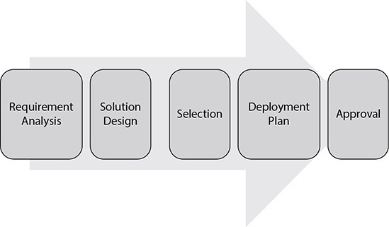
Figure 7-1 Planning phases
The first phase in the planning process is to identify the requirements for the system. Next, you design a solution based on the requirements. This then leads to selecting a solution that meets the requirements. This is followed by creating a deployment plan that outlines the steps necessary to deploy the solution, who will perform those steps, when the actions will occur, and how stakeholders will be kept up to date during the process. Lastly, the deployment plan must be approved by appropriate organizational decision-makers.
Requirement Analysis
The first phase of the planning process is called requirement analysis. The first phase in the planning process is to answer the question, “What do I need this cloud solution to do?” From this, you will then establish the other requirements for the solution to satisfy your user, business, compliance, security, and budgetary needs.
User and Business Requirements
The first part of requirement analysis is to determine the user and business requirements. User requirements define what the users will do with the system. For example, users may wish to track tasks in a task management system and have it automatically enter time for them in a time tracking system so that they do not have to track things twice. Another example might be users wishing to search an in-house knowledge management system for issues and problems that have been resolved to make troubleshooting future issues easier.
User requirements are often captured in a document called a user requirements document (URD). This document describes what the user is seeking from the system and formally documents that user’s needs.
Business requirements establish the anticipated benefits for the company, such as reduced expense entry time, support for a more interactive website experience, or better insight into customer purchase decisions. Similar to the URD, business requirements are often documented in a business requirements document (BRD).
Compliance Requirements
Depending on the type of data collected and the industry the business resides in, there may be some compliance requirements that the company will need to be aware of. For example, suppose the company is in the healthcare industry. In that case, HIPAA will require them to apply certain protections to healthcare data and patient records. If they are doing business in California or the EU, regulations like the California Consumer Privacy Act (CCPA) or the General Data Protection Regulation (GDPR) will require the system to notify users of the information being collected on them and govern how that data may be used and how users can request copies or removal of that data.
These requirements will need to be built into the application. The good news about developing in the cloud is that many cloud vendors have already implemented these features. Document the functions you require and then select a cloud vendor that has implemented these features. You will then need to ensure that those features are turned on and integrated correctly into your solution.
Some requirements that may come out of compliance include
• Data retention How long data will be stored. This may be defined for different data types. For example, customer data may be stored for 5 years, financial data for 10 years, and employee data for 20 years.
• Encryption requirements Encrypting data in transit or when stored to prevent those without the decryption keys from viewing it.
• Vulnerability management requirements Testing the system for weaknesses using vulnerability scanning tools or through penetration testing.
• Auditing requirements How security controls will be evaluated, tested, and validated.
• Privacy notices When and where users will be notified of their privacy rights and the privacy practices of the organization in regard to the system and the data collected.
Security Requirements
Security requirements will define how the data you store or process in the application is protected from loss or disclosure to unauthorized parties. Security requirements are derived from the risk level the organization is comfortable with and the potential threats to the data in the system. Some security requirements might include
• Authentication mechanisms How users log into the system. This includes password requirements and possibly the use of multifactor authentication.
• Log management How logs will be audited, archived, stored, and monitored.
• Patch management How often patches will be applied and in what manner.
• Privileges Access levels to data and system functions.
• Access How the system may be accessed, such as over the Web, via mobile devices, through remote administration consoles, and so forth.
• Hardening requirements How the system will be configured to reduce its attack surface.
Budgetary Requirements
The last part of requirement analysis is to determine the budgetary requirements. The business goals established earlier should provide the company with a measurable benefit. Based on that, the company will set a budget that will result in the desired return on investment (ROI).
ROI is a percentage and is calculated by taking the value of the system’s benefit, then subtracting the cost of the system. This is then divided by the cost times 100. The formula is shown here:
ROI = (Return – Cost) / Cost times 100
The budget is the amount that can be spent on the project. Project managers will need to ensure that their expenses do not exceed this number. Budgets may or may not include sunk costs such as employee time, so you will need to be aware of this when doing calculations.
Designing a Solution
The second phase is to design the solution based on these requirements. The solution needs to achieve the business and user goals within the established budget. The solution design includes how the system will be secured, how it will integrate with other systems or clouds, the technical design, and the amount of downtime required.
Security Design
In the security design phase, the team will evaluate the security requirements and determine how to implement them. For example, if multifactor authentication is required, the team will decide which type of multifactor authentication would best fit the solution and how that will be implemented.
A big part of the security design will be identifying the data flows in the system and how the data will be secured at different places. A data flow diagram is often created at this point. The data flow diagram shows the type of data and how it moves between system components, which networks it traverses, where it is stored, and whether it is encrypted or not at each point.
Another part of the security design is how the system will be segmented. You will need to determine whether certain functions need to be on their own networks and how access will be governed between those networks. A typical web application framework is to have web, database, and storage tiers. Web servers would sit in the web tier, database servers on the database tier, and the storage systems on the storage tier. In between each tier is a firewall with access control lists that define how traffic can traverse the networks. For example, users would be allowed to access the web servers over the Internet. Only the web servers would be able to connect to the database tier. Only the databases would be able to connect to the storage tier. This is a bit simplistic, as there might be some other services required to connect to these networks, such as backup or authentication services, but it serves to demonstrate how this part of the security design phase is performed.
Technical Design
The technical design outlines the computing resources and services that will be used to put the solution together. This includes software, hardware, networking, routing, and subnets.
Software The software portion of the technical design will include the applications that comprise the solution. This will consist of the software required for the user and business goals, as well as compliance and security goals. The user and business software are needed to meet those functional requirements, while the software necessary to implement security or privacy controls is specified for those elements.
For the functional portion, you will need to specify which operating systems the servers will run, the applications that will run on them, and the major service components. For example, a solution might require ten Fedora Linux installations. Five of those will be web servers, running Apache with PHP. Another five machines will run the MySQL database service.
The security and compliance portion will specify which software will provide the necessary controls. This may include intrusion detection or prevention systems, identify and access management systems, software firewalls or web application firewalls (WAFs), DNS, and authentication systems, among other software.
Some software will require licenses, so this is the time to calculate the license costs to determine the best way to satisfy the solution. Keep in mind your budget. You may need to adjust the software design if it exceeds the software allocation in the budget. You will also want to track when those licenses need to be renewed. In some cases, existing software licenses can be transferred to be used in the cloud solution. Transferring licenses in this way is known as bring your own license (BYOL).
An application architecture diagram is often created at this step. This will show the software that is in use and how it is integrated with other software. A software inventory spreadsheet is also commonly created at this stage.
Hardware The next part of the design will outline the hardware that is required to implement the solution. In an on-premises solution, this will include specifying the server type and size, then the processor, memory, storage, and networking included in each server. However, for some cloud resources, the hardware specified will be the vCPU, vNIC, and memory required for each server. If your solution is a SaaS solution, you will just specify the service that will be utilized, since the actual hardware required is not part of your consideration.
Network The next step is to design the network portion of the solution. Each system on the network will need an address to communicate. Most systems will require one or more IP addresses. Some systems, like storage devices, may require another type of address. Determine how you will assign those addresses. Some systems may have static addresses assigned, while others will receive theirs through an addressing system like DHCP. The network design will need to include these IP address scopes and the static addresses that will be assigned.
Another part of the network design is the segments and their purposes. Earlier in the security section, we defined different network segments. These segments often correspond to network virtualization technologies, such as VXLAN, NVGRE, STT, or GENEVE networks, which were covered in Chapter 4. Specify which systems will reside on which segments, the IDs, and names.
The network design will also need to include how network redundancies will be put in place, such as how many network connections systems will have and how those systems will be connected together to provide the appropriate level of resiliency. Enterprise configurations usually have at least two network connections to each server. Each of these connections will be cabled to a different switch to protect against cable failure, NIC failure, or switch failure. You will also want to consider how your switches will be connected to each other to avoid a single point of failure in the network.
Lastly, consider what other network services will be part of the solution. This could include network load balancers to distribute the load, caching systems, proxies or reverse proxies, and other network optimization systems.
Network Sizing As part of the network design, you will need to determine how much bandwidth and reliability are required for systems. This is especially important in cloud systems where network service levels may be assigned per resource. Review the application documentation to determine how much network bandwidth it will require based on the expected utilization. If you have a similar existing environment, collect network statistics to obtain a baseline for the application.
Routing Routing is required to allow network segments to communicate with one another. Even if you only have one network segment, you will still need to configure routing so that those devices can connect to the Internet. Routing is the network process that directs traffic from source to destination on different networks. Devices such as routers, firewalls, and layer 3 switches can perform routing. They do this by understanding the networks that they are directly connected to to send packets to the next leg of their journey, known as a hop. Routers may know of multiple paths to a destination, and they rank these by hop count (how many links the packet must traverse to get there). Lower hop counts are prioritized above higher hop count links so that packets are delivered as quickly as possible.
You will need to determine which routing protocols you will use on your network and whether you will have any static routes in place. Routing was discussed in Chapter 4, so please see that section for more detail on routing specifics.
Subnetting A single address space is usually not the right fit for an organization. Each segment will need to have a subnet within the overall address space for the systems on that network. The links between networks will also need their own subnets. The first step is to determine overall how many subnets you need, and then you can select which type of overall network you need. Table 7-1 shows classes A, B, and C of addresses and subnet masks. It also shows how many networks and addresses per network can be in each one before any subnetting occurs.
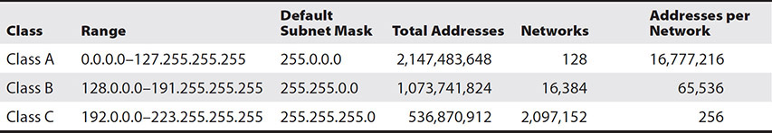
Table 7-1 Class A, B, and C Subnet Capabilities
Subnetting allows a single address space to be divided into multiple networks. This makes it easier to manage and can improve both performance and security on a network. The subnet mask is used to determine which network a system belongs to. Without subnetting, each octet in the subnet mask will be either a 255 or a 0.
Small sites may require only a few of the available addresses from even a class C address. Point-to-point WAN links only require two addresses but must reside on their own network. Without subnetting, a separate address range would have to be purchased for each site or WAN link, resulting in a large number of wasted addresses and inefficient use of resources.
Plan out how many networks you will need and how many hosts you will need on the networks. It is important to note that each network will have a network address and a broadcast address that you cannot use for your systems. Also, many virtual network subnets in the cloud reserve a few IP addresses for internal use.
Various subnetting tools are available for those setting up a network. One such tool is available on https://www.subnet-calculator.com. However, it is distracting to switch between a program and the calculator when doing regular tasks. Also, once you learn a few quick methods, you will be able to subnet so quickly that the task of entering subnet information into a calculator will seem laborious.
Computers use the subnet mask for an IP address to find which network the address resides in. The mask and IP address are combined in a process known as binary ANDing. The process works like this. Computer A wants to send data to computer B. Computer A will find the network address for computer B by ANDing B’s IP address and subnet mask and comparing it with its own, which is also obtained by the same process. At this point, most people resort to converting everything to binary, and everyone gets confused. That’s why I put together this different technique.
Let’s avoid that confusion by using this simple method. There are three subnetting tasks that you will want to be able to do. The first is to determine what subnet mask will satisfy your required subnets and hosts per subnet. The second is to determine which network an IP address resides on, and the third is to find out how many hosts and networks can be created from a subnet mask.
Determining the Subnet Mask When setting up an IP addressing scheme, you will want to know how many networks you can create and how many hosts will be in each network. A standard class C subnet mask without subnetting looks like this: 255.255.255.0. The standard subnet mask allows 256 addresses in a single network. However, only 254 of those addresses can be used for hosts because each network requires a network address and a broadcast address. These two addresses consume two of the subnet’s available ones.
An IP address is made up of four numbers, each separated by a period. When represented in binary form, these numbers, consisting of eight binary numbers, are referred to as an octet. Each digit can be a one or a zero. Ones represent network bits and zeroes host bits. Subnetting takes some host bits and turns them into network bits, dividing that one network into many networks with fewer hosts on each. Table 7-2 shows each of the possible class C subnet addresses and their binary form. Please note that the table does not offer options for one or zero host bits because one host bit would only allow a network and broadcast address, and zero host bits would not allow for even that, so both of those options would allow for zero hosts.
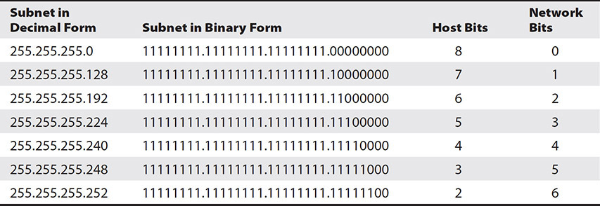
Table 7-2 Subnet Decimal and Binary Forms
The number of networks and hosts we can create depends on what class of address we are using. IP addresses can be class A, B, or C. In class C addresses, the first three octets are always used for network identification. An octet with all network bits has a value of 255. With three octets for networks, one is left for hosts. We can only steal host bits. Notice that we steal bits, but I have only mentioned octets. There are eight bits in each octet. Class B addresses allocate two octets, or 16 bits, to hosts, and class A allocates three octets, with 24 bits, for hosts.
Let’s find the subnet mask we would need if we want five networks given a class C address space. Borrowing one bit from the eight available host bits would provide two networks. This is because that one bit represents a binary number that can be either a zero or a one, so there are two options. As you increase the bits allocated, that value increases by a power of two. For example, with two bits, there are four possible combinations, and with three bits, there are eight possible combinations. Each time we borrow another bit, the number of networks double, and the usable networks is simply the number of networks.
It helps to know the powers of two when working with computers. For reference, Table 7-3 lists the powers of two up to ten. These “magic numbers” should look familiar to you because they crop up all the time when working with computers. For example, the number of colors supported with 16-bit color is 65,536 or 216. RAM modules come in sizes such as 128MB, 256MB, or 512MB. Take a little time to practice these steps, and you will soon be quick at subnetting.

Table 7-3 Powers of Two
We must borrow three bits to obtain five networks. We will actually have eight usable networks (23 = 8), of which we will use five. If we borrow three bits for subnets, there will be five bits left over for hosts because there are eight bits in the octet. The binary for this eight-bit octet would look like this:
Before subnetting: 11111111.11111111.11111111.00000000
After subnetting: 11111111.11111111.11111111.11100000
With five bits, we have two to the fifth, or 32, possible addresses, but we must subtract 2 for the network and broadcast address, so each network will support up to 30 hosts.
Borrowing three bits changes three zeroes in the last octet of our subnet mask to ones. Each binary bit has a value. Table 7-4 shows a chart that you can use to determine the decimal number for a binary octet. There are eight blanks where you can fill in the network and host bits as zeroes or ones.

Table 7-4 Binary Conversion Chart
Add the values in each place where you see a one to get the value for the octet in the subnet mask that is composed of a mix of binary ones and zeroes. Table 7-5 shows the binary octet when we borrowed three bits. Those bits are represented as the first three ones.

Table 7-5 Binary Conversion Chart
128 + 64 + 32 = 224, so this is the value of that octet in the subnet mask. Combine this together with the first three octets to get 255.255.255.224. Remember that the first three octets are used for network identification, so they are entirely composed of network bits or ones. An entire octet of eight binary ones (28) adds up to 255 if we count zero as the first number. For reference, Table 7-6 shows the subnet mask and how many subnets and hosts could be obtained from each class C mask.

Table 7-6 Class C Subnet and Host Addresses
Also included in the table is the Classless Inter-Domain Routing (CIDR) notation. The CIDR notation shows how many total bits are used for networks. In the class A addresses, you can see that the smallest one has a CIDR notation of /10. This represents the eight bits that make up the first 255 in the subnet mask and then the two bits borrowed for subnets.
Let’s try another example with a class B network. Our default class B subnet mask looks like this: 255.255.0.0 or 11111111.11111111.00000000.00000000 in binary, so there are 16 hosts bits. Suppose we want to find the subnet mask we would need if we want 100 networks with 500 hosts on each.
If we look back at Table 7-3, we see that borrowing seven host bits as network bits will give us 128 networks (27 = 128). We cannot go any smaller because six bits only gives us 64 networks. Borrowing seven bits leaves nine for hosts. The binary for this would be 11111111.11111111.11111110.00000000. With nine bits, we have two to the ninth, or 512, possible addresses, but we must subtract 2 for the network and broadcast address, so each network will support up to 510 hosts.
Finally, add the values in each place where you see a one to get the value for the octet in the subnet mask composed of a mix of binary ones and zeroes. In this case, it is the third octet, so we can use Table 7-4 again and plug the ones in to get 128 + 64 + 32 + 16 + 8 + 4 + 2, which equals 254, so the subnet mask is 255.255.254.0. For reference, Table 7-7 shows the subnet mask and how many subnets and hosts could be obtained from each class B mask.
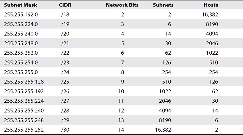
Table 7-7 Class B Subnet and Host Addresses
Just to round things out, we will do one more example with a class A network. The default class A subnet mask looks like this: 255.0.0.0 or 11111111.00000000.00000000.00000000 in binary, so there are 24 hosts bits. Suppose we want to find the subnet mask we would need if we want 1000 networks and the maximum number of hosts on each network.
If we look back at Table 7-3, we see that borrowing ten host bits as network bits will give us 1024 networks (210 = 1024). Borrowing 10 bits leaves 14 for hosts. The binary for this would be 11111111.11111111.11000000.00000000. With 14 bits, we have two to the fourteenth, or 16,384, possible addresses and 16,382 usable addresses once we subtract 2 for the network and broadcast address.
Finally, add the values for the ones in the significant octet. We need to find the significant octet because that is where we will focus our attention. The significant octet is the number that is neither 255 nor 0, or in binary, a mix of ones and zeroes. In this case, it is the third octet, so we can use Table 7-4 again and plug the ones in to get 128 + 64, which equals 192, so the subnet mask is 255.255.192.0. For reference, Table 7-8 shows the subnet mask and how many subnets and hosts could be obtained from each class A mask.
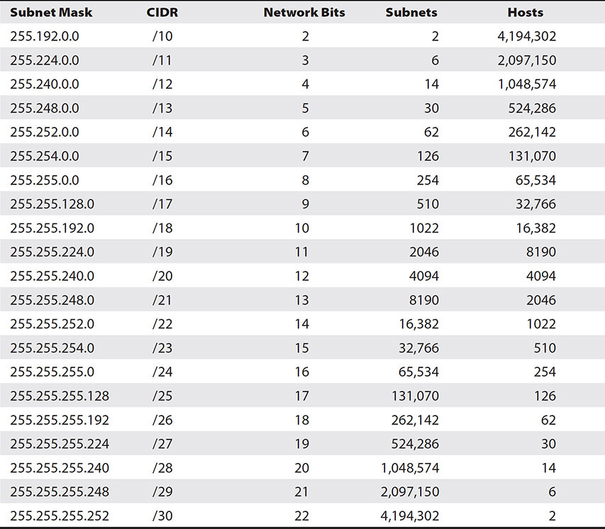
Table 7-8 Class A Subnet and Host Addresses
Finding the Network Number Now that we know how to determine what subnet mask will satisfy your required subnets and hosts per subnet, the next thing to learn is how to determine on which network an IP address resides. The network address is how we uniquely identify a network.
The first step is to look at the subnet mask. We need to find the significant octet because that is where we will focus our attention. If you remember, the significant octet is the number that is neither 255 nor 0, or in binary, a mix of ones and zeroes. There are 256 possible numbers in each octet, numbering from 0 to 255. Take 256 and subtract the number in the significant octet from it.
Next, look at the significant octet for the IP address. This is the same octet you evaluate for the subnet mask. Use the number you obtained in the first step, and ask yourself how many times that number goes into the number in the IP address’s significant octet, and then multiply that number by the number you obtained earlier to get the network address.
Let’s consider an example. Two machines, computer A and computer B, want to communicate, so we want to determine if a router will be needed to establish communication between them. If they are on the same network, no router will be necessary. However, if they are on different networks, a router will properly relay the packets to their destination.
Computer A has the IP address of 192.168.5.11 and a subnet mask of 255.255.255.240. Computer B has an IP address of 192.168.5.19 and the same subnet mask. These two machines may have the same subnet mask, but that does not mean that they are on the same network. As you know from the exercise earlier, this subnet mask gives us 16 subnets so that these machines could be on any one of those.
Let’s look at the subnet mask and find the significant octet. In this case, it is the fourth octet where you see the number 240. Take 256 and subtract the number in the significant octet from it to get 16. Now that we have the number 16, we are ready to move to the next step.
Next, look at the significant octet for computer A’s IP address. Remember that the fourth octet was significant, so the number we look at is 11. Ask yourself how many times 16 goes into 11. Sixteen goes into eleven zero times. Take 16 times 0, and you get 0. Now combine this with the rest of the address, and we have our network address: 192.169.5.0. Let’s take a look at computer B. Computer B has the same subnet mask, so we can skip step 1. Step 2 asks how many times 16 goes into 19. The answer is 1, so we take 1 times 16 and get 16. The network address for computer B is 192.169.5.16, so these two addresses are not on the same network, so their communication will require a router to communicate.
Finding Subnets and Hosts We can work backward to find the number of hosts and subnets from a subnet mask that has already been created. In our network example, we used the address 192.169.5.11 with a subnet mask of 255.255.255.240. From the table earlier, we see this is a class C address. We can find how many bits were stolen by converting the decimal number 240 from the subnet mask to binary. We only need to look at the last octet because the first three are used for network identification and thus are unusable.
We can obtain the binary of the decimal number 240 if we use the binary conversion chart introduced earlier. To begin, start filling in the chart by adding the numbers together from left to right until you get to 240, as shown in Table 7-9. Place a 1 in each slot where you added a number.

Table 7-9 240 in Binary
For example, 128 + 64 + 32 + 16 = 240, so the first four bits are ones. The rest become zeroes. Counting the host and subnet bits in this octet gives us four subnet bits and four host bits.
We use two formulas to find the available subnets and hosts using the number of bits for each. The number of subnets equals two raised to the power of the number of subnet bits. Two to the fourth is 16, so we have 16 available subnetwork addresses. Almost the same formula is used for the host bits, of which we also have four. Take two and raise it to the power of the number of host bits and subtract two, so the answer is 14. Our subnet mask 255.255.255.240 will support 16 subnets, each with 14 hosts.
Integration
The different components of the solution do not operate in isolation. You will need to design how they will work together. One portion of this is the data flow. How will data be exchanged between systems? Which data standards will be required to support this exchange?
Another integration element to consider is authentication. Will all the systems be part of the same authentication domain, or will they be broken up into separate units? You may choose to make them all part of the same domain for ease of management, or you might split them to isolate control over portions of the environment.
Downtime
If the cloud solution is replacing a current solution, the team will need to determine whether the implementation will cause downtime. Downtime is a period where the system is unavailable to end users. It is important to know the duration of the downtime and whether it can fit into existing maintenance windows or whether a new downtime will need to be scheduled and communicated to stakeholders.
Selection
The planning team will then select a solution that meets their requirements in the third phase. This includes evaluating the different offerings and weighing the pros and cons of each. Some key considerations include ensuring that the data and privacy provisions in contractual agreements meet security and compliance requirements and that SLAs are aligned with availability requirements.
Evaluate Cloud Offerings
Consider the different cloud offerings that can satisfy portions of your solution and weigh the pros and cons of these. This will involve evaluating their features, how others rate their service, and how their price fits into your budget.
Contractual Fit
The next step is to review the contractual provisions to ensure that they meet your business and compliance requirements. Two main areas to look at are the data privacy and security provisions and the service level agreement (SLA).
Data Privacy and Security Provisions Data privacy and security provisions specify how the CSP will protect the systems that you are using. You will want to ensure that the contract specifies how quickly the CSP will notify you in the case of a data breach or other security incident affecting you and your customers. Shorter notification times will give you more time to perform your portion of the investigation to determine whether notification is required, who needs to be notified, and its impact on your company and its customers.
You will also need to make sure the contract has sufficient privacy protections to meet your compliance requirements. Make sure that the contract specifies how long the CSP will retain data if it is responsible for that portion of the service. You will also want to ensure that they provide methods to export the data in standard formats to avoid vendor lock-in and that they ensure the same compliance in their providers that they rely upon to provide the service to you.
Service Level Agreement Another necessary contractual provision is the SLA. The SLA will specify the promised maximum amount of downtime and service credits or other payments provided to the consumer if it exceeds that maximum. They may also define the workflow for handling technical issues. Ensure that the SLA meets your application requirements and the SLA that you are providing to your own customers. You cannot give your own customers an SLA that exceeds the SLAs of the cloud services your solution relies upon.
Deployment Plan
The fourth phase of the planning process is to put together a deployment plan that outlines the steps necessary to deploy the solution, who will perform those steps, when the actions will occur, and how stakeholders will be kept up to date during the process.
Tasks
With the cloud service selected and the solution designed, the team can now break the deployment down into discrete tasks. Next, determine how much time will be required for each task and then determine dependencies. Sometimes, groups of tasks will together form a milestone.
Some tasks are dependent upon others. These are known as sequential tasks because they must be performed in a particular order. Other tasks may be performed simultaneously. These are known as parallel tasks. The tasks should be documented in a task tree. Sequential tasks are placed in a row, with each task leading to the next. When tasks can be performed in parallel, they form a branch off the task tree. A sample task tree is shown in Figure 7-2.
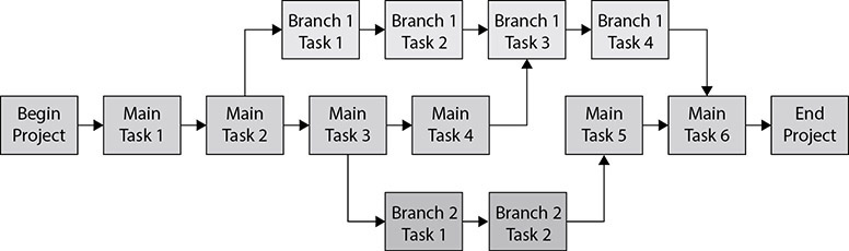
Figure 7-2 Task tree
The diagram shows the main tasks that then branch off into two different branches. Later steps in the main path are dependent upon the completion of the branches, and task three in branch one is dependent upon both the task before it and main task four. There is a period where the main task path must wait for branch three to complete before main task five can be started. This is a potential area where the planner might be able to put more resources in later to speed up the completion of the overall project.
Assign Responsibilities
Tasks will need to be performed by one or more people. You will need to assign these responsibilities to appropriate personnel or teams. Your task tree may need to be adjusted if parallel tasks require the same personnel, since a person cannot be in two places at once. This is a chance to identify alternative resources that may be able to perform the task. The result of this process will be a work breakdown structure. The work breakdown structure can take many forms, but a sample is shown in Figure 7-3.
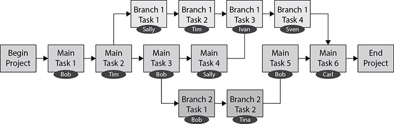
Figure 7-3 Work breakdown structure
Timeline
The next step is to take the tasks that were identified earlier and plot them out on a timeline. First, choose a reasonable starting date. Next, plot out the steps from the work breakdown structure. Give each one a date based on the estimated duration for the task and its dependencies. Some tasks may have the same due date because they are being performed in parallel.
You will also need to consider other dependencies, such as the availability of resources when assigning dates. For example, a step in the process requires a report that is received from a vendor every 30 days, and the task must be completed within 7 days of receipt of the report. You would need to ensure that the schedule meets this requirement.
The timeline process is not something that is done arbitrarily, but in coordination with those who will be performing the tasks. Discuss each step to ensure that the timeline represents realistic, achievable goals. A sample timeline is shown in Figure 7-4.
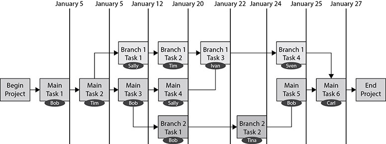
Figure 7-4 Timeline
Communication
It is important to keep stakeholders informed of the expected duration of the project and significant project milestones. You might also need to notify customers or employees of downtimes that will occur. Document these communications as substeps in the plan and document whether deliverables will need to be shared with those people. Deliverables could be reports of data moved or users migrated or an update to a project plan.
Overall Project Plan
A project plan is a final step in the planning process. This document should include all the information put together in the previous steps, such as the step, deliverable, dependency, assigned person, estimated duration, and due dates. Many plans include reference numbers for each task so that you can refer to the task by the number rather than the task description. A sample project plan is shown in Figure 7-5.

Figure 7-5 Project plan
Approval
The last step is to get the deployment plan approved by the appropriate organizational decision-makers. Typically, the project plan and budgetary items are distributed to the stakeholders. The project manager will explain how the project will meet the business and user goals and how it will stay within the prescribed budget. They will walk the stakeholders through the timeline for completion and then seek approval to move forward. Some projects require approval from multiple groups before the project can begin. Ensure that you have sign-off from those who are authorized to approve the project before you start the project activities.
Implementation
Hooray! The planning process is finally complete, and you are approved to begin implementing the solution. The implementation phase involves contracting with cloud providers for their solutions; developing the software that will be deployed; and then deploying the virtual systems, networks, and containers that comprise the solution.
Service Model Solutions
Implementation strategies for deploying solutions in the cloud differ based on the service model. As you remember from Chapter 1, some of the cloud services models include IaaS, PaaS, SaaS, and CaaS.
IaaS
IaaS solution deployments involve the cloud consumer implementing systems on top of a CSP’s storage, networking, and other supporting infrastructure. IaaS cloud deployments involve the following high-level steps:
1. Create virtual machines
2. Install operating systems
3. Install software or roles
4. Configure firewall rules
The first step is to create virtual machines in the cloud. You will create or migrate a virtual machine for each server that is part of your solution. For example, you may have several web servers, two database servers, a domain controller, and a file server.
The next step is to install operating systems on each of these servers. Once this is complete, install applications or enable server roles on the virtual machines so that they can perform their assigned role. For example, you may need to install SQL Server on a database server or enable the Active Directory or DNS roles.

NOTE If you are migrating from a different environment, steps 2 and 3 would be replaced with a P2V or V2V conversion of the existing systems into the cloud.
Lastly, configure firewall rules to allow appropriate traffic to your systems. For example, a web server would need an access rule to allow data over port 443 to and from it.
PaaS
PaaS solution deployments involve the cloud consumer implementing systems on top of an operating system provided by the CSP. The CSP supports the operating system, along with the underlying storage, networking, and other supporting infrastructure, so the deployment focuses on the application components.
In a PaaS solution, you would provision the systems using the cloud self-service tools and then select the necessary software to be included on them. The CSP then deploys the systems for you. One example of this is serverless computing, mentioned in Chapter 1, where the CSP provisions the system and manages its resources transparently to the cloud consumer. You would then need to configure access rules to the systems.
SaaS
SaaS deployments involve provisioning users and configuring options within an on-demand software application delivered by the CSP over the Internet. Deploying to a SaaS solution would involve provisioning accounts or licenses for your users and possibly migrating data from one solution into the SaaS solution.
CaaS
CaaS deployments involve provisioning users and configuring options within an on-demand voice over IP (VoIP), e-mail, or messaging application delivered by the CSP over the Internet.
VoIP To deploy a cloud VoIP solution, first provide the cloud vendor with the telephone numbers you will be migrating. The next step is to purchase phones. This is an optional step because you can use a cloud software-based VoIP solution without any physical phones. The cloud vendor may support multiple phone models, or they might require you to purchase the phones from them.
There are two types of VoIP phones: softphones and hard phones. Softphones are those that are implemented entirely via software. An application on a computer or a cell phone app can be used to send and receive calls. Softphones are very useful because they are often integrated into other messaging suites so that you can easily schedule conference calls on your calendar or initiate calls from a chat window. You can also easily move around with a softphone rather than being tied to your workplace. Since the software can be installed on multiple devices, you could have the software installed on your work machine and a home machine or a cell phone. This allows you to take calls in each of these locations. However, it can be slightly annoying to hear a computer, cell phone, and a hard phone all ring at once when a new call comes in. Softphones can also be used in conjunction with hard phones. Hard phones are physical phones that connect to the cloud VoIP system to make calls.
When the phones arrive, you will connect each one to the network to ensure that they have Internet access and then follow the steps from the cloud provider to link each phone with a user. A user may be associated with a hard phone and multiple softphones.
The last step is to cut over from your existing phone system. Much like moving to a new cell phone, on the cutover date, the existing phone numbers are moved from the current phone system to the new one. At this point, the old phone system can be retired.
E-mail Cloud e-mail systems are prevalent today. There are many solutions out there, but two of the most popular are Microsoft Office365 and Google’s Gmail. If you are a new company setting up cloud-based e-mail, the process is as simple as purchasing and assigning a domain name for the e-mail, then purchasing licenses for each user. The users will then log into their e-mail, set their password, and can begin sending and receiving mail immediately.
For established companies, e-mail is a fundamental technological need, so these companies most likely already have some solution. This could be an in-house system such as Microsoft Exchange, Sendmail, HCL Notes, and many others, or it could be an existing cloud e-mail system.
You will need to follow the instructions from the cloud vendor to migrate an in-house system to the cloud. This often involves establishing a federation between the local system and the cloud system. The cloud system is then configured as a front end for the local system so that mail flows through it and then back to the local system. You then use migration tools to begin moving accounts from one system to another. This allows for e-mail to route to the appropriate mailbox during the migration.
When migrating from one cloud provider to another, first ensure that the cloud provider supports migration from your existing solution. If they do, you can use their migration tools to perform the migration.
Messaging The last type of CaaS is a messaging system. These systems allow teams to easily communicate with one another via chat. Employees can easily see others on their team or look up employees to communicate with them. Messaging systems are much easier for long-running conversations. It is much easier to track a conversation using these programs rather than going through a long chain of e-mails. Files and pictures can easily be embedded into the chat so that teams can coordinate work in one place.
Deploying a messaging system is as easy as licensing the users through the cloud portal, installing the messaging software on systems, and then having users log into the application with their cloud credentials. Some solutions do not even require the installation of software. For example, chatting on the Google Workspace requires only a browser. There are often phone apps that can be used too, so that using the messaging solution is as easy as sending a text message.
Solutions
A variety of cloud solutions can be deployed. We already mentioned some of the communication solutions. Some other popular solutions include
• Web services
• Collaboration tools
• Financial solutions
• CRM
• Identity management
• Directory services
Web Services
Web services are one of the most well-known cloud services. Cloud consumers can easily create websites by signing up for one of these services. The cloud provider hosts the website and often maintains the back-end content management system (CMS), such as WordPress, Drupal, Joomla, or Magento. This allows the cloud consumer to focus on developing the content for the website. This could be anything from an informative company site to an e-commerce platform or a blog.
Collaboration Tools
Collaboration tools are designed to make it easier for teams to work together and manage projects or tasks.
• Document collaboration Document collaboration tools, such as Google Docs, Microsoft SharePoint, HyperOffice, and Box.com, allow multiple people to access, edit, and comment on documents as they are developed. These solutions provide a portal where the documents reside. The portal can be organized with a hierarchy consisting of folders, and access can be assigned at file or folder levels. Document collaboration tools track the changes made to files using a version history so that previous versions of documents or individual changes with the documents can be viewed. Changes are marked with the user who made the change.
• Project management Solutions like Trello, Asana, and Monday allow users to create projects and then track and assign tasks within projects. They offer visual tools so tasks can be moved around between different buckets to show status. Comments can be placed within tasks to keep team members and project managers informed of the status.
Financial Solutions
Financial solutions allow companies to perform accounting or other financial functions online through a single portal. These include accounting tools like QuickBooks and benefit and payroll tools like ADP.
CRM
Customer relationship management (CRM) software offers an easy way for salespeople and managers to identify leads, contact those leads, track engagement through the sales pipeline, and track sales productivity metrics.
Identity Management
Identity management solutions help track and manage users’ access to enterprise resources. Identity management systems can be linked to a variety of cloud services or in-house systems that an organization wishes to manage. Credentials are then provisioned for users, and access can be granted to those systems. A user does not need to have access to all systems, and their access to a particular system can be granularly managed. Individual application roles can be mapped to roles with the identity management solution so that it is easy to establish access to multiple resources for a single employee, contractor, or customer role.
Directory Services
Directory services are used to organize computer and user entities within one or more domains. Each entity has a unique identifier within the domain. Users can be assigned permissions and roles that govern their access to resources. Directory services can also be connected to one another to provide access to resources for users in other domains or federations.
Deploying Virtual Systems
You will likely find yourself needing to deploy virtual systems to the cloud. This section discusses how to deploy virtual machines, virtual appliances, and virtual desktops to cloud systems.
Virtual Machines
If you are using an IaaS solution, you will be deploying the systems to the CSP’s infrastructure. However, in PaaS solutions, you will use the CSP’s self-service portal or other tools to create new virtual machines. In both solutions, the deployment of virtual systems is quite streamlined.
The first step will be to determine the performance needs of the virtual machine. Cloud VM deployment can be performed through a guided deployment from the cloud portal, templates, custom images, or CLI scripting languages.
Guided Deployment The wizard-based guided deployment is often the easiest for a small number of VMs because the system walks you through all the options. You will choose to create a new machine and then be able to select from various performance profiles. Each profile comes with an associated monthly cost. For example, at the time of writing this text, a low-end Azure VM in their Bs-Series costs $2.74 per month and is a fairly bare-bones setup with few resources. Toward the other end of the scale is the H-Series with 60 vCPU cores, 4GB of RAM per core, four logical drives, and 260 GB/sec of memory bandwidth at the cost of $581.08 per month. It is easy to vertically scale the VM later on to a profile with more resources. The idea is to right-size the VM so that it achieves your required performance and capacity at the lowest cost.
These VMs come in Windows or Linux. The wizard will walk you through configuring the remaining settings, such as networking, security groups, and remote access. The primary disadvantage to the guided deployment is that it is very repetitive for large-scale deployments, and it lacks some configuration options.
Templates VM templates are virtual machines that are already partially configured. VM templates are typically generalized so that unique system identifiers are generated when the template is used to create a new machine. These templates allow for new virtual machines to be rapidly created. Cloud vendors often use templates to spool up new machines quickly when requested, and you can use them too. Templates can be divided into two types: OS templates and solution templates.
• OS templates OS templates are VMs that are preconfigured with the operating system but no other software. These are best used when you are creating a new virtual machine that will have a unique role but run a standard operating system.
• Solution templates Solution templates are VMs that are preconfigured with the operating system, patches, applications, and software dependencies, such as frameworks or necessary supplemental tools. Cloud vendors have a marketplace of solution templates that you can choose from to meet your needs for specific applications.
Custom Images Custom images can also be created. Custom images are highly configured templates that can be used to quickly deploy an almost entirely functional machine. Custom images are often made when you know you will create many VMs of the same type, such as web servers or virtual desktops, because they take more time to configure and reduce deployment time.
Appliances
Virtual appliances are self-contained software solutions that perform a specific role. These are often provided by a vendor. For example, you may wish to deploy a spam firewall as a virtual appliance in your cloud. You can purchase the system and obtain a VM from the vendor that you load into your cloud instead of plugging in actual hardware. There are also open-source appliances that you can download for free.
Virtual Desktop Infrastructure
Virtual desktop infrastructure (VDI) is a method of providing a desktop PC experience to end users over the network or cloud. VDI solutions use virtualization to host multiple desktop operating systems. Users connect to their desktops over the Internet from a variety of devices, such as thin clients, laptops, or tablets. The desktop software runs within the cloud or data center, isolating the processing, storage, and networking from the system that accesses the VDI.
VDI hosts many virtual desktops on the same host. VDI can be configured as persistent and nonpersistent. Persistent VDI allocates a virtual desktop per user, and user changes to that specific machine are retained. If the user downloads a file to the desktop or changes configuration settings, those settings will remain. Users will be connected to the same machine when they return. The advantage of persistent VDI is that users can personalize their desktop and customize it for their work or continue work from day to day.
In nonpersistent VDI, users are connected to whichever desktop is available, rather than a specific one. Changes are not retained on the desktop, and each desktop system is identical. The advantage of nonpersistent VDI is that it is simpler to deploy and manage because IT does not need to support custom configurations. If a desktop system is not working correctly, it can be removed and replaced with an identical one without changing the user experience.
Scripted Deployment
You can develop scripts to perform a wide variety of virtual deployment tasks with minimal effort. For example, you could automatically spin up new VMs from templates or custom images, deploy appliances, or move VMs between performance tiers. Scripts can be kicked off manually or be scripted to execute based on certain conditions, such as expanding a VDI with more virtual desktops when a new employee is hired. Rather than walk through a process many times, a script could create many machines in one operation. Scripts can also be optimized to perform many tasks in parallel to accelerate the deployment process.
Networking
Cloud systems require many different networking components to function correctly. Some of these components may be configured by the CSP, but others you will need to configure. This section covers virtual networks, cloud firewalls, virtual routing, VPNs, and VPCs.
Virtual Networks
You may need to establish virtual networks to connect your VMs or segment VMs into different networks. Companies typically segment different types of machines so that they can strictly govern the type of traffic allowed between zones. For example, you may have a virtual network for web servers and allow connections from the Internet to this zone. You can then specify another network for virtual desktops and only allow connections to this network over a VPN.
Exercise 7-1: Creating a Virtual Network in Azure
In this exercise, we will create a virtual network in Azure. Note: You will need to have an Azure subscription to perform this task. You can sign up for a free 12-month subscription if you do not have one.
1. Sign in to the Azure portal (https://portal.azure.com).
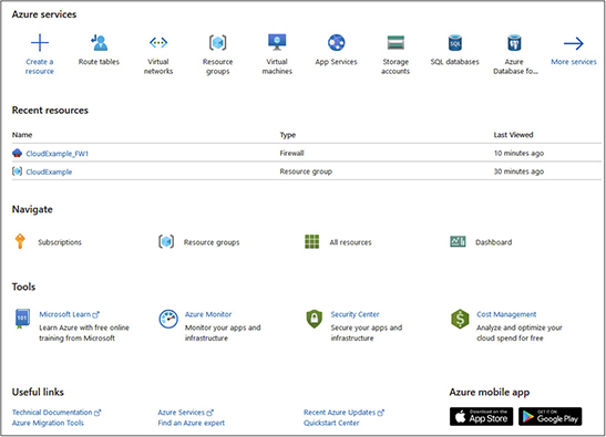
2. Select Virtual Networks. When the screen changes, select the Add button.
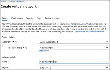
3. In the Create Virtual Network screen, enter the following options. Select your Azure subscription in the subscription drop-down box. Then select a resource group. The resource group chosen for this example is one that I created previously called CloudExample. Name the instance CloudExample_Net1 and choose a region. In this example, we chose the East US region. When you are done, your screen will look like this:
4. Click the blue Review + Create button at the bottom. This will display a screen that shows you the values you just entered. Click the blue Create button at the bottom.
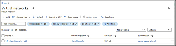
5. The deployment will take a few minutes. When it is done, you will see a screen like the following illustration, stating that the deployment is complete. Click the Go To Resource button.
Cloud Firewalls
Firewalls are devices that sit between networks to govern the traffic flow. They use access control lists (ACLs) to determine which traffic is allowed and which should be denied. There are a variety of other, more advanced features. Cloud firewalls are discussed in more detail in Chapter 11. This section explores how to deploy them. Cloud vendors will often have firewall functionality that you can configure within the cloud portal.
Common features that are available to consumers include defining the traffic types allowed and which machines can receive that traffic. You may also be able to specify inspection rules from a set of prebuilt templates. You can also deploy firewalls as virtual appliances. Many of the same companies that make hardware firewalls also make virtual appliances with the same functionality. These firewalls can offer features that built-in firewalls do not have, or they can allow for a company to implement a consistent firewall strategy within each cloud and on-premises location by using a mix of cloud and hardware firewalls along with centralized management tools.
Virtual Routing
Virtual routing is necessary in order to make various virtual networks talk to one another. A virtual router makes decisions on how to send and receive data between networks based on the routing protocol configured on it. Each routing protocol uses a specific method to determine the best path a packet can take to its destination. Some routing protocols include Border Gateway Protocol (BGP), Interior Gateway Routing Protocol (IGRP),Open Shortest Path First (OSPF), and Routing Information Protocol (RIP). BGP uses rule sets; IGRP uses delay, load, and bandwidth; OSPF uses link-state; and RIP uses hop count to make routing decisions.
Cloud vendors will often have routing functionality that you can configure within the cloud portal to specify static routes or enable routing protocols.
Static and Dynamic Routes Static routes are manually configured instructions that tell a router always to send traffic over a specific link. These differ from dynamic routes that are built using routing protocols that obtain routing information by querying neighboring routers. Dynamic routes can change with network conditions such as a failed link, but static routes will not change.
Static routes are often used for routing where there is only one option, such as the default route that establishes a single connection to the outside world. They do not require updating, so they use fewer system resources on the router. Dynamic routes are best when there are multiple possible ways to get from source to destination. Dynamic routes can determine the most optimal path to take and can automatically adjust based on link availability. However, they do need to be maintained, and this consumes processing on the router and network resources when exchanging routing information with other routers.
Exercise 7-2: Creating a Default Route on Azure
In this exercise, we will create a static default route in Azure.
1. Sign in to the Azure portal (https://portal.azure.com).
2. Type route tables in the search bar at the top and select Route Tables once it appears. You will be presented with the following screen:
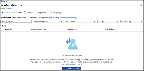
3. We will need a route table before we can create routes. Click Create Route Table.
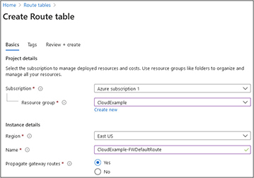
4. Select your Azure subscription in the subscription drop-down box. Then select a resource group. The resource group selected for this example is one that I created previously called CloudExample. Select a region from the drop-down box. In this example, we selected East US. Give the instance a name. In this example, we called it CloudExample-FWDefaultRoute, as shown next. Click the blue Review + Create button at the bottom. This will display a screen that shows you the values you just entered. Click the blue Create button at the bottom.
5. The deployment will take a few minutes. When it is done, you will see a screen like the following illustration, stating that the deployment is complete. Click the Go To Resource button.
6. Now that we have a route table, we can create routes inside it. Under settings, on the left side, select Routes.
7. When the route screen appears, click the Add button.
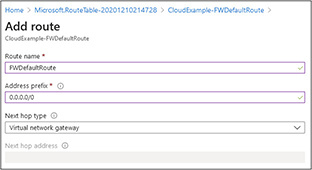
8. The Add Route screen will appear. Enter a route name. In this example, we named it FWDefaultRoute. Set the address prefix to 0.0.0.0/0 so that it will be used for target addresses that are not covered by other explicit routes. Set the next hop type to the virtual network gateway, as shown next. Click the OK button at the bottom.
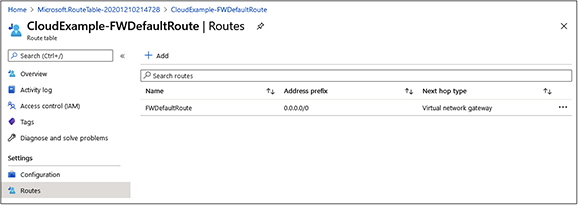
9. It will take a moment for the rule to be created. Wait for the screen to display the new rule, as shown here:
Virtual Private Network
A virtual private network (VPN) connects systems over a public network, such as the Internet, so that they can operate as if they were on the same LAN segment. A VPN can connect multiple office locations together into a single network, or it can be used to connect remote employees into the company’s cloud. It is quite common to create a VPN to cloud resources so that users can access those resources like they would for local office servers. VPNs are also used by administrators to perform maintenance and other tasks.
Virtual Private Cloud
A virtual private cloud (VPC) is used to isolate resources within a public cloud for an organization. A subnet is created for the VPC, and then the resources are segmented off from other cloud resources with one or more VXLAN, NVGRE, STT, or GENEVE segments and associated routing and access control lists to govern traffic flow. Traffic that exits the VPC is encrypted.
NOTE Microsoft refers to their VPC as a VNet, not a VPC, with no difference in functionality from other cloud providers’ VPCs.
Hub and Spoke The hub and spoke VPC model funnels connections back to the VPC in the cloud. The VPC acts as the central place for communication. As you can see in Figure 7-6, each of these offices is connected together and to the cloud resources through the VPC.
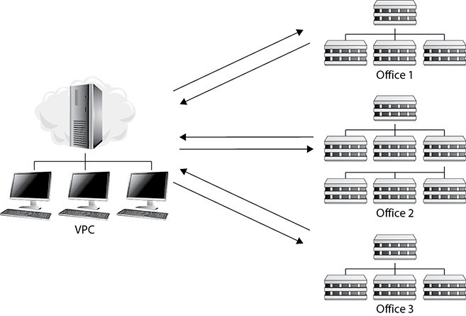
Figure 7-6 Hub and spoke VPC
Peering VPC peering is a way to link multiple VPCs together over the SCP backbone. You may do this if you have several cloud accounts from the same CSP that you want to connect together into a shared network space. Mergers and acquisitions often go through this, but it is also very common when multiple departments set up cloud resources and then later determine that they should be shared with other parts of the organization.
Still, VPC peering can be a planned event from the beginning when combining the best from multiple cloud providers into a single solution or solution set. The advantage of VPC peering over other connection methods is that the traffic does not traverse the public Internet. Rather, the traffic flows through the network links owned and operated by the CSP using private IP addresses instead of public, Internet-facing ones.
To set up VPC peering, the owner of one VPC sends a peering request to the owner of the other VPC. Once the request is accepted, static routes will need to be created in each VPC to point to the other. Next, configure security rules to allow traffic between the VPCs to the resources you want to share. Lastly, enable and configure hostname resolution for the VPC connections so that systems will be able to connect to resources by name.

CAUTION Make sure that you are using distinct IP address spaces before you set up VPC peering. Otherwise, you will have IP conflicts.
Containers
Containers are isolated silos that house applications. Containers should not be confused with virtual machines. Containers are much smaller than a virtual machine because they only need to retain their application components, not the underlying operating system. This means that they consume less storage space and less memory than deploying applications over virtual machines. Containers can be created or destroyed at will so that they only consume resources when they are needed. Running containers typically use nonpersistent or volatile storage, such as memory, to operate. Some primary features of containers include their isolation, portability, and ease of deployment.
Containers isolate applications because they are self-contained. An application within a container is packaged with all the code, runtime libraries, files, dependencies, and frameworks necessary for its operation. Because of this, containers do not interfere with other applications or containers that run on the machine. Containers allow you to have multiple versions of the same application or multiple applications that rely on their own framework versions that can run on the same platform without conflict. This is a great way to test new applications or various application builds in parallel without interfering with existing applications. It also gives you the freedom to deploy applications without worrying about their impact on the host system other than their resource consumption.

EXAM TIP Container isolation is considered lightweight isolation as compared to the isolation provided through virtual machines. Dedicated virtual machines for applications offer more security boundaries between applications that run on different VMs.
Containers allow for easy portability because they are platform agnostic. Containers operate within a container runtime that is installed on the platform to serve as an interface between the container and the platform, much like the virtualization layer between a hypervisor and guest virtual machines. Container vendors, including Docker, Google, and CoreOS, created the Open Container Initiative (OCI) to create open container format and runtime standards. OCI has released a runtime specification and an image specification to aid in developing standard runtime support on different platforms. The same application can easily run on multiple different platforms that each have the container runtime.
Containers are easy to deploy because DevOps teams do not need to troubleshoot compatibility issues or perform machine-specific configurations in order for the applications to run in the environment. More extensive applications can be broken down into many smaller pieces that are each containerized. These containers can then be combined into a larger unit called a cluster that is then managed with a container orchestrator, such as Kubernetes.
Configure Environment Variables
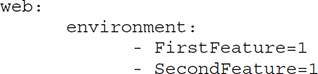
Environment variables are used by containers to store values that can be used to customize the application. Environment variables are often used to enable or disable features or customize them for a customer or setting. Here are some examples for setting environment variables for different container runtimes.
The following code will assign two variables, FirstFeature and SecondFeature, the value of 1. If this were a feature that you wished to enable, you could do it by setting these values to 1 and disable them by setting their values to 0.
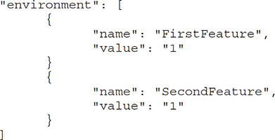
This is the same code that will run on Amazon:
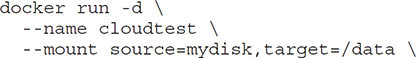
This code sets the environment variable in the Azure CLI when creating a container called cloudtest:

Configure Secrets
Secrets are items that must be protected from unauthorized access. They include data such as passwords, private keys, SSL certificates, or other sensitive data. Secrets are stored and transmitted in an encrypted form. Only authorized containers can access the data in the secrets.
The following code creates a Docker secret named AppCertificateFingerprintSHA-1 and assigns it the value 9F:FB:59:0D:2F:62:0E:DF:58:30:EE:02:17:97:2D:4F:CE:09:EB:6C.
docker secret create AppCertificateFingerprintSHA-1 9F:FB:59:0D:2F:62:0E:DF:5
8:30:EE:02:17:97:2D:4F:CE:09:EB:6C
CAUTION Do not pass sensitive information to your containers using environment variables because environment variables are not encrypted. This could expose those passwords to others and compromise the security of your container. Use secrets instead.
Configure Storage
Containerized apps utilize storage that resides outside the container for data. This is ideal because the container is typically running in nonpersistent storage, and many containers may need access to the data. Containers access storage by mounting the volumes or bind points within the container.
Mounting a volume allocates the entire logical disk to the container, while bind points allocate a directory tree consisting of folders, files, and subfolders to the container. Volumes usually provide better performance, but bind mounts are better used for shared configuration files. The following code mounts a volume called mydisk to a folder called data in the container called cloudtest:
Post-Deployment Validation
The last step in the deployment process is to validate that the application accomplishes the user and business requirements set forth at the beginning of the project. Establish specific test cases to evaluate this and then go through a checklist to ensure that each objective is met. Do not rely on just a single person to do this validation. Ensure you have a good sampling of testers, including stakeholders who sponsored and suggested the need for the solution in the first place.
Remote Access Tools
The cloud computing environment is inherently in a different location from the working environment because of the environment needs servers have and the economies of scale that can be achieved by housing thousands of servers in the same place. The cloud consumer might not even know where the cloud provider’s servers are being hosted. This is why remote access is required to manage, service, and maintain systems.
Remotely accessing a server does not always have to mean accessing the server from an offsite location. There are times when simply connecting to a host computer or virtual machine from a workstation is more convenient than physically walking over to the server and logging in. When a quick fix or change needs to be made to a virtual machine or host computer, accessing that server from a local workstation saves time. Remote access prevents the need to walk or drive to the data center and physically sit at the machine that requires the change.
Being able to remotely access and troubleshoot a virtualization host or virtual machine requires less time and makes fixing and maintaining the environment easier to accomplish. Some remote access tools include remote hypervisor access and Remote Desktop Protocol (RDP).
Remote Hypervisor Access
There are a variety of ways to remotely connect to a hypervisor. Most vendors allow a console to be installed on a workstation or server that is not the hypervisor. This allows a user to manage the hypervisor from their workstation. The machine with remote management tools is often referred to as a jump or step machine. Multiple hypervisors can be managed from a single console on a workstation, giving a single-pane-of-glass approach to hypervisor management.
Remote hypervisor tools enable administrators to perform most host management tasks as if they were connecting directly to the actual hypervisor. The client console gives them the ability to create or modify virtual machines or virtual hard disks, configure virtual machine settings, and so on. This allows them to do all the administrative tasks that are required on a day-to-day basis from a single workstation.
Users of remote hypervisor tools need to have the correct administrative permissions on the hypervisor to modify the host computer’s settings or the virtual machines. Using a console from a workstation is an excellent way to connect to a hypervisor host because it looks and acts just as it would if the user were locally logged into the hypervisor host.
RDP
RDP differs from installing the hypervisor console on a workstation. It allows for remotely connecting and logging into the Windows-based hypervisor host’s desktop. RDP provides remote display and input capabilities over the network. RDP connections are made through software that supports RDP over TCP port 3389. RDP is built into Windows machines and can be executed by typing mstsc from the command prompt or run command. Figure 7-7 shows an example of RDP client software that is used to connect to a hypervisor host remotely. RDP is a multichannel protocol that provides separate virtual channels for transmitting device communication and presentation data from the server.
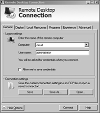
Figure 7-7 Remote desktop connection: An example of RDP software
Employing a Console to Connect to a Remote Hypervisor Host
I remember a time when I was working with an organization that had deployed multiple hypervisor hosts in its environment. The organization had a total of 20 hypervisor hosts and 250 virtual machines. The data center that the hypervisor hosts were installed on was in an adjacent building, and the time it took administrators to walk to the data center was time that they could have spent doing other tasks. The organization needed a way to centrally manage the hosts from the administrators’ workstation computers without logging in to each one individually.
The solution was to install the console on each of the administrators’ workstations and add the hypervisor hosts into the single console. This allowed each administrator to see all 20 of the hypervisor host computers and manage those hosts. It was a great solution that satisfied the organization’s needs by saving the administrators’ time and effort and managing all 20 hypervisor hosts from a single console. The console installed on each workstation looks and responds just like the console installed on the hypervisor host computer.
The advantage of using RDP to connect to a hypervisor is that the user has direct access to the hypervisor server without having to be physically sitting at the hypervisor host. RDP allows users to interact with the server just as if they were sitting in front of it. So instead of just having access to the hypervisor console, RDP enables access to the entire server. The user can launch other applications on the server, as well as change system settings on the hypervisor host computer itself. RDP allows for complete control of the server operating system, not just the hypervisor settings, without physically attending the hypervisor host computer.
One of the disadvantages of using RDP for managing a virtualization environment is that an administrator cannot manage multiple hypervisor hosts in a single RDP session like a remote hypervisor client console. The option to use RDP is currently only available for the Microsoft hypervisor. Connections made to other modern hypervisors such as VMware, Citrix, and Oracle require the use of a software client installed on a jump machine.
Console Port
A console port allows an administrator to use a cable to connect directly to a hypervisor host computer or a virtual machine. The administrator can use a parallel or serial port to connect peripherals to a virtual machine, add serial ports, and change the logical COM port configuration. The virtual serial port can connect to a physical serial port or a file on the host computer. Using a console port allows for managing a virtualization host computer directly from another computer connected to the host computer with a console cable.
SSH
The Secure Shell (SSH) protocol provides a secure way to manage network devices, including hypervisor hosts, remotely. SSH is capable of using public-key cryptography to exchange a symmetric key covertly between the SSH client and the SSH server, creating a fast and secure channel, and then using that channel to authenticate a remote computer and user if required. It can also use a traditional username and password for authentication. The default port for SSH is port 22.
SSH can use a manually generated public-private key pair to perform authentication. The symmetric key is used to encrypt the connection. SSH can be used to log into a remote computer and execute certain command strings against a hypervisor host machine.
SSH provides strong authentication if using the latest version and secure communication over an insecure channel. It was designed to replace remote shell (RSH) and Telnet because RSH and Telnet send unencrypted traffic over the network, making them insecure communication methods.
When designing a virtualization environment, it is not recommended to directly expose the hypervisor host to the Internet. Normally, the hypervisor host is installed behind a firewall or some other form of protection, which makes it difficult to access the hypervisor host off-site. SSH allows for the creation of a secure management tunnel to the hypervisor host computer or virtual machine and provides a secure way to manage those devices, since all the traffic is sent through an encrypted tunnel.
EXAM TIP SSH provides a way to access a hypervisor host or virtual machine securely from an off-site location.
HTTP
Another option for remotely accessing a hypervisor host machine is through a web console using HTTP or HTTPS. Hypertext Transfer Protocol (HTTP) is an application protocol built on TCP to distribute Hypertext Markup Language (HTML) files, text, images, sound, videos, multimedia, and other types of information over the Internet. HTTP operates by default over port 80, and HTTPS operates by default over port 443.
HTTP typically allows for communication between a web client or web browser and a web server hosting a website. Most hypervisor vendors have a web console that allows an administrator to access a hypervisor host from virtually anywhere as long as the hypervisor’s DNS name can be resolved and HTTPS access is permitted through perimeter devices.
Administrators may have to install an additional component when doing the initial hypervisor host installation to provide web access to a host computer. The hypervisor host web service should be configured to use HTTPS to ensure a secure way to connect. Some hypervisors (like Microsoft IIS) may require additional software on the host computer as well. Connecting to a hypervisor host computer using a web console is a quick and easy way to perform simple configuration on a virtual machine.
Chapter Review
The importance of planning before deploying cloud solutions cannot be overstated. This chapter provided you with the tools and techniques to conduct the requirement analysis for a new solution, design that solution, select a cloud offering, and then build a deployment plan. This is then presented to management to seek approval for deployment. We then walked through the implementation of various cloud solutions and virtual systems, networking, and containers. Finally, remote access tools were described so that you can manage the systems you deploy in the cloud.
Questions
The following questions will help you gauge your understanding of the material in this chapter. Read all the answers carefully because there might be more than one correct answer. Choose the best response(s) for each question.
1. Which of the following are steps in the requirement analysis process? (Choose all that apply.)
A. Technical requirements
B. Compliance requirements
C. User and business requirements
D. Data requirements
2. You are planning the network for a new VDI cloud deployment. You need seven networks, and the largest subnet will have 25 hosts on it. Which subnet mask would you choose for a class C network?
A. Console port
B. SSH
C. Hypervisor console
D. 255.255.255.224
3. You are reviewing a cloud service contract to determine if it is the right fit. Which section would you review to determine the maximum amount of downtime allotted in the contract?
A. Data privacy and security provisions
B. Indemnification
C. SLA
D. Force majeure
4. You are reviewing a cloud service contract to determine if it is the right fit. You receive an alert that a virtual machine is down. The server does not respond to a ping. What tool should you use to troubleshoot the server if you are off-site?
A. Console port
B. SSH
C. Hypervisor console
D. SMTP
5. Which of the following would you use to remotely access a virtualization host in a secure fashion?
A. Telnet
B. Ping
C. HTTPS
D. Console port
6. The primary stakeholder for your project has asked for a document showing the responsibilities of each task. Which document should you send them?
A. Task tree
B. Work breakdown structure
C. Timeline
D. User responsibilities design
7. You would like to deploy a new task management system to your cloud. The vendor offers a virtual machine that has its software already installed and configured on it. What should you look for in the cloud portal to deploy this?
A. Solution template
B. Custom image
C. VDI image
D. Software download link
8. You are deploying a container to a QA platform so that multiple testers can begin evaluating the application. What would you use to enable certain functions within the application for each test group?
A. Configuration settings
B. Secrets
C. Deployment scripts
D. Environment variables
9. Which of the following would be used to directly connect to a hypervisor host remotely to modify operating system settings on the hypervisor host?
A. RDP
B. Console port
C. SMTP
D. HTTPS
10. Which of the following is a benefit of remote hypervisor administration?
A. Only being able to modify one hypervisor host at a time
B. Being able to remotely manage multiple hypervisor hosts from a single console
C. Not having access to a hypervisor host
D. Remotely accessing a hypervisor host has no benefit
Answers
1. B, C. Requirement analysis consists of (1) user and business requirements, (2) compliance requirements, (3) security requirements, and (4) budgetary requirements.
2. D. 255.255.255.224 has three subnet bits, allowing for eight subnets and five host bits, allowing for 30 hosts per subnet.
3. C. The SLA specifies the promised maximum amount of downtime and damages provided to the consumer if it exceeds that maximum.
4. B. Secure Shell (SSH) provides a secure way to remotely manage network devices, including hypervisor hosts.
5. C. HTTPS gives you a way to access a virtualization host remotely in a secure fashion.
6. B. The work breakdown structure shows each of the tasks and whom they are assigned to.
7. A. A solution template will provide you with the software in the marketplace, and the software will already be packaged within the VM for deployment.
8. D. Environment variables will allow you to enable or disable certain features from the containerized application.
9. A. The Remote Desktop Protocol (RDP) lets you establish a remote connection directly to a hypervisor host. It allows you to change system settings on the hypervisor host computer itself.
10. B. The ability to remotely manage multiple hypervisor hosts from a single console from your workstation allows for a quick and easy way to make changes to multiple hosts and is an important benefit of remote hypervisor administration.