
Network Security Protocols and Defensive Mechanisms
We are increasingly concerned that we are not using wired Ethernet for PC access to the networks but are wirelessly connecting to access points, and our access link tends to be a variation of the 802.11 standard, with Wi-Fi Protected Access (WPA)2 for wireless security and Internet Protocol Security (IPSec) for encryption and routed network security. However, security issues continue to plague our networks. Border gateways between certain autonomous networks are used at the borders to facilitate communication across networks. Since these are located at the border of networks, they tend to be more vulnerable; therefore, we use Secure Border Gateway Protocols (S-BGP) to provide a level of security. Domain Name System (DNS) rebinding also has a secure version, which we’ve also started using. This is known as a Domain Name System Security Extension (DNSSEC). Further, network engineers have developed perimeter defenses, which look like firewalls. Their functions are varied and include packet filtering of stateless and stateful packets. Specifically, these filters look for things that should be allowed through. In this chapter, there will also be an evaluation of anomalies that could represent a threat to the network. More specifically, time-of-day markets will be examined in further detail.
Basic protocols that will be assessed in this section include Internet Protocol (IP), Transmission Control Protocol (TCP), User Datagram Protocol (UDP), Border Gateway Protocol (BGP), and a combination of DNS and Dynamic Host Configuration Protocol (DHCP). There are a multitude of security issues with these protocols. Regarding IP, there is no source validation, and it is also fairly easy to sniff these packets and spoof connections by guessing TCP sequence numbers. Concerning BGP, it’s fairly easy for hackers to advertise bad routes and close good ones. And in the case of DNS, cache poisoning and rebinding are quite common and affect overall web security mechanisms that rely on the DNS for address resolution.
This is one of the key IP security and encryption protocols. One of IPSec’s sub-protocols is the Internet key exchange (IKE), a standard protocol used to ensure security negotiation for virtual private networks (VPNs) and, in particular, the negotiation of remote access by hosts or edge devices to an IP network. IKE’s primary task is concerned with negotiating the IPSec security association (SA), which is a relationship between two or more entities that describes how the entities will use security services to communicate securely. IKE (or IKEv2) is the protocol in the IPSec protocol suite that is used to set up an SA. IKE builds on the Oakley protocol and the Internet Security Association and Key Management Protocol (ISAKMP), which is a protocol defined for establishing SAs and cryptographic keys in an Internet environment. IKE uses X.509 certificates for authentication—either preshared or distributed using DNS (preferably with DNSSEC) and a Diffie–Hellman key exchange—to set up a shared session secret from which cryptographic keys are derived. This process requires that the IPSec systems authenticate themselves to each other and then proceed to establish ISAKMP (IKE) shared keys.
The source IKE sends an IKE message, which creates a secure channel between two IKE peers, the source and destination IKE peers. An encryption key is used as the Diffie–Hellman key agreement. This type of agreement is considered a superior encryption to the popular Rivest–Shamir–Adleman (RSA) encryption discussed in Chapter 8.
The source IKE negotiates an IPSec SA and generates the required key materials for encrypting and decrypting. The sender offers a set of transformations. The receiver then accepts one of the transformations.
The sequence of exchanges is portrayed in Figure 15.1.

Figure 15.1 IKE/ISAKMP process of negotiating an IPSec security association.

Figure 15.2 Process of creating an IPSec tunnel for transmitting encrypted packets.
Frequently, a certificate of authority is added to the process. A message is sent out to a radius server, the purpose of which is to have the radius server authenticate the message that is being sent across the IP network.
The sequence for this process is illustrated in Figure 15.2.
This process includes a set of access lists that, in combination with the encryption, increase the level of security components.
Layer 2: Link-Layer Connectivity of Wireless
Our society’s growing need for mobility has led to the increased use and adoption of the 802.11i wireless connectivity standard, which specifies security mechanisms for wireless network connection. In this protocol, the network attempts to set up the secure transfer of information from the source to destination. This includes a supplicant, an authenticator, and an authenticating server (usually a radius server). On one side of the communication is the supplicant; in the middle is the authenticator and the authenticating radius server. The authenticator uses the radius server to supply encryption keys that will provide secure communication with the supplicant over an unsecure IP network. For this protocol, there are five layers of communication that require agreement between the source and destination.
TCP/IP Basic Layer 2–3 Security Problems
The following all comprise big issues for IP/TCP:
■ Eavesdropping
■ Packet sniffing, which enables controlling of machines
■ TCP state can be guessed, which enables spoofing
■ Session hijacking
Defense Mechanisms That Can Be Employed
For protection over unsecured IP networks, companies increasingly employ VPNs using IPSec as the encryption algorithm and IKE as the requesting mechanism for passwords.
There are three different modes used for VPN:
1. Remote access client connections
2. LAN-to-LAN internetworking
3. Controlled access within an intranet
Several Different Protocols Then Apply to These Modes
PPTP: Point-to-Point Tunneling Protocol
L2TP: Layer 2: Tunneling Protocol
IPSec: Layer 3: network layer (includes the Diffie–Hellman encryption process)
IPSec
There are two varieties of IPSec, one of which is an extension for IPV4 and the other for IPV6. Furthermore, IPSec includes an IP authentication header. This safeguards the authentication and integrity of the payload and the header itself. An encapsulation protocol is used to enhance the confidentiality of the payload and the headers. Encapsulating security payload (ESP) is another member of the IPSec protocol suite. In IPSec, it is used to provide integrity check values that can be combined with other prior tools to provide confidentiality and data origin authentication.
The basic packet formats in the TCP/IP variation of the Open Systems Interconnection (OSI) seven-layer data communication model include a message originating in Layer 7 (application layer), which is usually broken up into 1500 byte parts, and then each part of the message is separately included in a data field of a Layer 4 (transport layer) segment with a TCP header. That Layer 4 segment is then included as the data field in a Layer 3 IP packet with an IP destination address. Next, the IP segment is included as a data field in a link-layer frame at Layer 2, with its own header containing a Layer 2 address, frequently an Ethernet address. Thus, the resulting unit to be transmitted contains a portion of the original message plus a series of Layers 6, 5, and 4 headers, if there are any, plus TCP, IP, and Ethernet headers. There are as many of these units transmitted as can contain all of the 1500 byte portions of the original message to be transmitted. The headers and data fields created at each layer of the transmission model are illustrated next to their respective layers in Figure 15.3, which shows the sequence of the inclusion of those successive headers included with the transmitted unit sent out over the network.
A source will encrypt its packet data in the header, and it is sent over an encrypted tunnel. The receiving device will then decrypt the packet. However, prior to this, it will receive authentication keys to ensure the integrity of the packets when IPSec is used.
Figure 15.4 provides a more detailed view of the process, which now includes IPSec protocol.

Figure 15.3 Packet formats and layers.

Figure 15.4 IPSec tunneling mode and TCP/IP layers.
Filtering Network Traffic at the IP Level
Network traffic at the IP level is often filtered through a firewall at the perimeter of the receiver’s network. A firewall is typically placed at the connection point of the local company network and the public Internet to filter traffic that comes from the public Internet and goes to the local company network. Firewalls of this nature implement a set of access rules defining what packets are to be allowed, blocking all others that do not meet those access parameters. All packets between the local area network (LAN) and the Internet are routed through the firewall. The firewall screens the packets coming in and evaluates them based on a stored set of valid parameters. If they match the valid criteria, packets are allowed through, and if not, they are blocked. Outbound packets may also be screened but generally under less stringent criteria.
Several steps are involved in basic packet filtering. First, the firewall will evaluate incoming packets that are arriving. They will be evaluated based on a set of specified criteria. Often, the set of valid criteria against which incoming packets are matched up will include a list of valid IP source addresses and destination addresses. The next step is to use Layer 3 transport layer header information, TCP, or UPD data. An evaluation of valid protocol information, specific TCP and UPD ports, specific flags that are allowed or not, and ICMP message type should be included. The Internet Control Message Protocol (ICMP) is one of the main protocols of the IP suite used by network devices such as routers to send error messages indicating that a requested service is not available or that a host or router could not be reached.
An example of a proper port relationship to protocol or device would include a DNS that uses port 53. A filter can be provisioned with the specification to block incoming port 53 packets, except those associated with a known trusted server.
Concerning capability, filters may be programmed to look for source or destination address forgery. However, as with all security systems, some main issues arise concerning firewalls. Stateful filtering is hard to achieve, encapsulation via address translation may lead to complications, and fragmentation may throw off comparisons to valid rule information. The filtering examples in Figure 15.5 portray the evaluation of inbound Simple Mail Transfer Protocol (SMTP) packets. SMTP is an Internet standard for electronic mail (e-mail) transmission. SMTP by default uses TCP port 25.
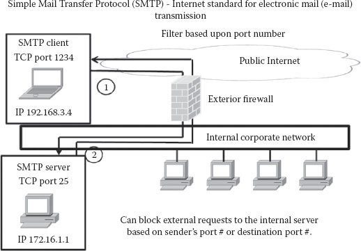
Figure 15.5 Filtering example of INBOUND SMTP message.
Firewall Stateful Packet Filtering
Keep in mind that third-generation firewalls maintain records of all connections passing through the firewall. This process is commonly recognized as stateful packet inspection. Firewalls can determine whether a packet is part of an existing connection or if it contains parts of a new connection. If a user inside a company network requests information from outside the network, the firewall will likely let this type of traffic through; however, if the traffic is coming in from the outside without an initiated request from the inside, the traffic will not be allowed, unless a specific firewall specification enables this type of traffic to be allowed through.
Telnet is a protocol used by an external client to open up a channel for a client to connect with a server. Telnet is a user command and an underlying TCP/IP protocol for accessing remote computers. Through Telnet, an administrator or another user can access someone else’s computer remotely. The client sends a message requesting to set up a connection to the respective port on the server. The server will then acknowledge the submitted request. However, if the acknowledgment bit is not set while the connection is established, then the server will not provide this acknowledgment.
The TCP three-way handshake is similar. The client establishes a communication channel, and the server then proceeds to acknowledge the channel. However, as an additional step, the client sends another acknowledgment affirming the connection (acknowledging the returned acknowledgment).
File Transport Protocol (FTP) also operates with a similar process of establishing communication channels and acknowledgments. However, it differs in that the issue of the data and the command ports set on the FTP server are separate. However, acknowledgments between the FTP client and the FTP server continue to be transmitted. The FTP is a standard network protocol used to transfer computer files from one host to another host over a TCP-based network, such as the Internet. FTP is built on a client–server architecture and uses separate control and data connections between the client and the server.
Normally, the data to be transmitted is separated into 1500-byte sections, with each section placed into the data field of an IP packet. However, in specific cases, data that is to be transmitted into smaller 596-byte sections for special transmission situations may be fragmented down to a 596-byte section plus header packet. Smaller packets tend to pass through some networks more quickly due to their smaller size. Note that despite this fragmentation of the initial message, it is the sum of all packets containing the message parts that comprise the transmission of the complete message. Figure 15.6 showcases an example of the fragmentation of a 1500-byte packet into three 596-byte packets.

Figure 15.6 Normal IP packet fragmentation process.
Abnormal IP fragmentation is also commonly performed by hackers. Although this can be done by users performing normal, valid activities, it is also frequently employed by hackers. The discrepancies in the way these packets are fragmented are found in abnormal or inconsistent uses of IP headers and TCP headers. Other problems such as data overlapping can be part of the hacker routine. Figure 15.7 illustrates this non-standardized IP packet fragmentation technique.
As a result of this fragmentation practice, hackers have learned to leverage this process as an attack. This in turn has resulted in what we call packet fragmentation attacks, a common practice. Hackers leverage this by sending in fragmented packets. This causes the firewall to ignore the second packet of a complete packet message that is fragmented in the appropriate way. The result: damage due to the subsequent included information.

Figure 15.7 Abnormal IP packet fragmentation processes.

Figure 15.8 SSL security process.
Secure Socket Layer (SSL) was the predecessor to transport layer security. SSL is a computer networking protocol that manages server authentication, client authentication, and encrypted communication between servers and clients. These protocols allow a client to authenticate a server and establish an encrypted SSL connection, which is designed to enable secure communication from one area of the network to another through the use of authentication and encryption. A choice notice is sent to the server by the client. The server responds with a certificate. The client then sends back a secret key. This communication is followed by a negotiate cipher, which then culminates in the exchange of hash sequence messages from both sides.
The process is illustrated in Figure 15.8.
Corporations use local IP addressing inside their local network using the IP addresses in the form of 10.0.0.0. When leaving the local network, the normal IP address scheme is employed in the form of 176.221.54.10 on the outside worldwide networks. This local address scheme is used because there are only a limited number of addresses available, particularly with version four of IP (IPV4). Corporations will place a proxy server at the edge of the network. This will allow the outgoing traffic to apply for a loaned outside IP address. Traffic will then be sent with an appropriate outside source and destination address to the outside destination. Everything that is going outside is passed from the edge router to the proxy server, which validates the mapping of the external network. For returning traffic, the proxy server will then translate the external IP addresses and map them to internal local network destinations to ensure proper communication.
IP proxy servers are not only located at the edge of the network. Corporations often employ specialized proxy servers, which range in types from Telnet to FTP to SMTP proxy servers. Application-level proxies are also available for use. These are specific to predetermined applications.
It is possibly useful to scan and examine outgoing and incoming web traffic, especially when corporations and network administrators have a specific set of well-known dangerous sites. The traffic for these known bad sites can be scanned and intercepted if necessary. Additionally, these scanning tools can block attachments of certain specified types. JPEGs, GIFs, bitmaps (BMPs), attached pdfs, and other file types can be blocked through the use of this feature. Blockings can take place based on the types of protocols, types of content, and the numbered port to which the message intends to connect.
Intrusion detection systems tend to be placed on networks with increasing frequency as a direct result of the increasing amount of network attacks attempting to penetrate organizational security systems. In combination with modern personal techniques that range from social engineering to spear phishing, these types of attacks can pose a significant threat to the network. Intrusion detection systems monitor activity on the local company network. They can be network or host based, or a combination of both. There are two basic models:
1. Misuse detection model
2. Anomaly detection model
Note, however, that the primary task of these systems is to search for abnormal network traffic and behavior. There is a whole set of systems. One example of these systems is called Snort. Snort works with UNIX-based systems. It operates with Windows. It is able to see and decode packets. It is looking for specific criteria, and if it identifies those criteria in the packet, it sends an alert message to the network administrators.
Some of the challenges affecting Snort and other intrusion detection systems concern the amount of rules observed in the databases. These databases tend to grow very large, and they may allow known intrusions to avoid detection. Snort also spends up to 80% of its time running string matches, which is simply one task. Finally, given the fact that Snort works on an anomaly detection pattern basis, the probability of identifying new attacks is diminished, as most of these anomalies are older.
There are many problems with anomaly detection patterns themselves. For these systems, it becomes hard to distinguish between abnormal traffic behavior and normal behavior. Another hindrance that adversely affects these systems is the need for training data. Further, note that much of the data that is actually captured during these training data phases is normal data and contains little evidence of realistic attacks. Assuming this, it is not uncommon for misidentifications concerning the nature of network traffic and data to be made.
Two Critical Infrastructure Protocols: BGP and DNS
The BGP and DNS systems represent areas of major vulnerability for networks since they both serve a between-network function, with BGP routers physically located at the edge of two networks. If affected, damaged, or compromised, they can disrupt the networks they are attached to. They are typically built in sets. The border gateway area is a place where traffic can be blocked, and it is typically also a target area for hackers to attempt router poisoning. Similarly, poisoning of the DNS is also quite common. Observe the set for BGPs shown in Figure 15.9. Routers 1–8 are border routers, containing the structure of the networks on each side and providing the routing information for interarea bridging of transmission. BGP provides each area network with the physical and logical interarea bridge function for interarea routing of communications.

Figure 15.9 A Border Gateway Protocol (BGP) example.
Note that BGP is used for all routing between Internet service providers (ISPs). Benign configuration errors impact 1% of all routing table entries at any time. BGP routers are extremely vulnerable to malicious attacks as well as human errors. When those attacks are successful, one area network is unable to communicate with neighboring area networks. To enable a secure BGP design, it’s important to leverage IPSec and also to leverage public-key infrastructures, distributed valid certificates, and digitally signed authorizations.
Infrastructure Protocols for DNS and DNSSEC
Figure 15.10 shows a user PC with a stub resolver, a local recursive resolver DNS server in the center; a set of root zones, each with their own local DNS servers, then create a multilevel local DNS. Every Internet low-level DNS can do all these translations. When one DNS server is down, others can pick up the slack.
DNS by design is insecure. Packets to and- from the DNS server are all UDP with no acknowledgment. This means they are best-effort transmissions. There is a great deal of reliance on the source port, with no real evidential reliance on whether it is valid, and the caches are easily poisoned. A more secure approach will be presented with DNSSECs. The DNSSEC is a future system that would require a very elaborate DNS system, which would change the apparatus of the DNS. Resource records would all be secured and encrypted, and all of the source and destination addresses would have to be validated.
If a human error occurs when typing in an alias, then it is assumed that when the DNS lookup takes place, the DNS system should return a denial-of-existence message. A large portion of the communications or messages going into the local and Internet DNS servers will result in no translation, and a lot of excess traffic ends up with no translation result.

Figure 15.10 DNS and DNSSEC infrastructure protocols.
A DNS rebinding attack is a form of computer attack wherein a malicious web page will cause visitors to run a client-side script that attacks machines somewhere else in the network. In many cases, the DNS will allow these attacks through. In the example, the message looks valid. The DNS lookup also looks valid. Given these two assumptions, if the DNS system is corrupted, then it will forward the message under the assumption that the information is valid. Some defense mechanisms for DNS rebinding attacks include the following:
■ Browser mitigation
■ Server-side defenses
■ Firewall defenses
The intent of network control firewalls is to determine a hardened set of parameters that would block externally sourced attacks. If the incoming messages don’t meet the criteria outlined in the firewall, they should be blocked. One approach is to have each system turn off unnecessary network services. Certain kinds of things will always be blocked. Management packets are typically blocked if they are issued from outside.
Another example of what might be blocked is associated with SMTP, which is an Internet standard for electronic mail (e-mail) transmission. SMTP by default uses TCP port 25. The protocol for mail submission is the same but uses port 587. SMTP connections secured by SSL, known as SMTPS, default to port 465 (non-standard, but sometimes used for legacy reasons). Although electronic mail servers and other mail transfer agents use SMTP to send and receive mail messages, user-level client mail applications typically use SMTP only for sending messages to a mail server for relaying. We might decide to only allow connection to port 25 and block connection to ports 587 and 465.

Figure 15.11 Firewall packet filter allowances and drops.
Firewalling is a very complex process. A potentially more scalable defense would be to reduce risk by blocking or restricting network access to any outsiders. There are chokepoints associated with firewalls, and such chokepoints can cover thousands of hosts.
Selecting a security policy is complex. One rule could be that any user can connect to any service and any user outside. Another option is to limit certain services and websites by incorporating a list of invalid sites. External users can be limited to certain applications and services. The default for these policies is to allow external access to services and deny non-well-known or insecure services. Basic packet filters with a set of access control rules also need to be set up via the router. These access control rules are combinations of source and destination information and addresses at multiple layers.
A basic kind of firewall is considered a packet filter. The access control rules are used to examine and filter IP packets. The rules specify simply whether these packets are allowed to pass through to the local network or are denied entry. For example, any TCP/IP packet that looks a certain way will be allowed or denied. There’s a specific rule that sets IP and another for TCP or for allowed combinations of TCP ports and IP addresses. The most stringent ones include explicit drop and allow parameters. We certainly want to be careful when it comes to allowing all IP addresses. Rule sets look like that shown in Figure 15.11.
Incoming packet types need to be distinguished as well. For example, when the website responds to our query, then general rules apply, such as the allowing in of any incoming packet that was associated with an outgoing connection.
Security Principle Reference Monitors
As a best practice, network administrators should introduce reference monitors to oversee the flow of traffic across their network. Reference monitors should always be invoked to examine all packets going across the network. All operations have to be mediated, which means that if these monitors don’t like the communication, they can block the packet. A good portion of the scanning of these devices’ performance is based on observing behavior. Factors such as time of day, type of communication, content, and source and destination are all closely monitored to detect abnormal behavior. This is behavior over and above what a firewall would normally be able to oversee and block.
Potential problems associated with these reference monitors include wireless network access points. Users can easily access or leverage these unsecured access points, and this may pose a security threat to the internal network. A program called NetStumbler allows hackers and prospective attackers to drive by a wireless-enabled laptop and gain access to an internal network. Ideally, reference monitors are tamper resistant. This is to protect the monitor itself and to protect the integrity of the data it is monitoring. As a maintenance approach, network administrators should connect locally to these devices in order to reduce the risks of a breach. Unfortunately, there are a variety of other risks that can affect or subvert firewalls. Poor administrative practices and IP tunneling can weaken reference monitors.
Overall, there are many advantages associated with implementing firewalls. They have a central point of control, they are easy to implement, and there’s also a lot of experience regarding their implementation and access control rules. The disadvantages of these defense systems include the fact that some applications are immune to or incompatible with firewalls. Firewalls may lead to some functionality loss as there might be less connectivity. Finally, older firewalls are becoming less and less effective.
In summary, we have performed an evaluation of network security protocols and defense mechanisms, specifically examining firewalls.
QUESTIONS
1. What is DNSSEC and why is it important?
2. What are two ways IPSec provides security service?
3. IKE provides three different methods for peer authentication. What are they?
4. What is the difference between an intrusion detection system and an intrusion prevention system?
5. Is an intrusion detection system the same as a firewall?
6. An intrusion detection system has two basic models. Explain the role each performs for the intrusion detection system.