
Chapter 10
Forestage Zone
The forestage is the three-dimensional zone where a proscenium stage and auditorium meet. The forestage geometry may be static or flexible, but it is always a transition zone between performance space and audience space. Very often the forestage has movable parts to create an extension of the stage apron, additional audience seating, or orchestra pits of differing sizes. It may be heavily equipped with rigging, lighting, and audio technology to allow the extension of the production design into the auditorium.
This chapter examines the typical elements and design considerations of the forestage zone, but keep in mind that it’s a rare theater space that incorporates all of the elements described here. We’ll start at stage level, move below the stage to the lowest level of the building, then work our way back up to the roof above.
Apron
The apron is the area of the stage between the house curtain and the stage riser or orchestra pit. It should be deep enough for the performance of entr’actes—short scenes performed in front of the closed curtain—but not deeper than necessary. Our objective always is to keep the first row as close as possible to the plaster or setting line, where the full production capacity of the stagehouse is available.
Apron Entrances
The apron may have entrances on each side from vestibules on the auditorium side of the proscenium wall. (If these aren’t provided, the performers enter the apron from the center split in the house curtain.) The area above these entrances is often used for stage lighting, video monitors for the performers onstage, and other production equipment. If the side loudspeaker clusters aren’t “flown,” then the entrances themselves may be filled with loudspeakers stacked at each side of the apron.
Adjustable Proscenium Opening
If the proscenium width is to be adjustable, this may be accomplished with framed, architecturally finished panels on the apron side of the proscenium wall. These “tormenter” panels are hung on barn door tracks and may also have a guide track in the apron floor. A matching header panel may be used to adjust the height of the opening. All panels are kept to a minimum thickness so as not to increase the distance between the first row and the stage. If the production calls for it, the stage opening may be further reduced by a scenic portal or draperies on the stage side of the proscenium wall.
Apron Edge
The front of the apron is defined by the orchestra pit opening, or by the stage riser if there is no orchestra pit. At one time, built-in footlights were a common feature of the apron edge, but electric footlights were actually a holdover from the pre-electric age and are rarely used today. (The British term floats refers both to footlights and to the apron edge where footlights were once common. It derives from the use of floating candles as light sources.)
Cable Trough
The footlights are gone, but a continuous trough with removable covers is often built into the apron edge. The trough is used to access power and control outlets below the apron edge and to route temporary cabling across the front of the apron.
Front Fill Loudspeakers
The audio designer may specify small loudspeakers built into the apron edge, spaced every four to eight feet or so. These loudspeakers cover the first few rows of seats, an area that the primary speakers overhead may not reach. The front fill speakers also provide localization—that is, they enhance the perception that the sound is coming from the apparent visual source on stage and not from speakers overhead.
Apron Edge Marking
Stage edge markings have been included in recently built theaters as a fall prevention measure. The markings may be tactile or visual, and visual markings might include reflective or luminescent strips or LED lamps positioned so they are (mostly) only visible to the performers. Curbs may be added to prevent wheeled equipment from falling off the stage edge. Yes, this does happen—before his career as a lighting designer, in his first gig as a stage manager, Gilbert Hemsley rolled a concert grand piano into the orchestra pit. If there is an orchestra pit, a netting over the pit is another possible safety measure. A properly designed netting can catch a falling person or a thrown object, but would not have saved the grand piano.
Multiple Apron Edges
If the forestage zone is reconfigurable as described below, the apron may have multiple front edges, and the features described above may be repeated at each edge. Expensive items, such as front fill loudspeakers, may be designed to be repositioned. Certain features, such as a curb at the apron edge, are not workable if there are multiple apron edges.
Access from Auditorium
Movement between the auditorium and stage may not be desired in some venues, and the apron will be designed with no direct access from the auditorium. In other venues—a school auditorium, for example—direct access to the stage may be a requirement. When a direct circulation path is provided, the ADA requires a direct accessible route that coincides with or is close to the circulation path. A common solution is to extend the stage apron around the sides of the auditorium to form a level or ramped area at each side of the center seating. These side areas can be developed as boxes or parterres providing wheelchair seating locations with direct access to the stage. The level or ramped areas can extend to a crossaisle, giving access to additional wheelchair seating locations at the center of the orchestra floor. In the latter case, the side areas can be used as caliper stages.
An alternative often seen in existing theaters is to provide steps from the front of the auditorium up to the stage apron. This situation doesn’t satisfy the ADA requirements, unless a wheelchair lift is provided adjacent to each set of steps, and that will not please anyone. For this reason, most theaters built today do not have steps up to the stage apron. One does often see portable steps between the auditorium and stage, sometimes combined with a temporary walkway over the orchestra pit. These are usually placed by the theater operator as a convenience for the cast and crew during rehearsal and work calls. They should be removed for performances and other public events. Unless an adjacent wheelchair lift is provided, these step units are technically in violation of the ADA. However, unlike the architect, an onsite operator is in position to hear and respond to any concerns.
Pass Door
Whether stage access is provided within the auditorium or not, all theaters need a pass door providing wheelchair-accessible, non-public access between the backstage and front-of-house. This is usually provided in the forestage zone, but immediately off stage and out of public view. If possible, pass doors should be provided on both sides of the forestage.
Orchestra Pit
Early orchestra pits were placed between the apron edge and the first row of audience seating and were completely open to the auditorium volume. Most pits today extend below the apron edge, so that part of the pit is open to the auditorium and part is covered by the apron floor above. The pit configuration is determined by the nature of the performance and by requirements for sightlines, hearing, and accessibility.
Pit Size
Pit size is largely determined by the largest number of musicians needed for the planned programming. A general rule of thumb is to provide 16 to 18 NSF of floor area per musician. For small ensembles, the unit area may be increased to 20 NSF. In all cases, the pit size and shape should be tested with draft layouts of the expected ensemble sizes.
Broadway
Productions in New York’s Broadway theaters employ no more than 20 musicians, and usually fewer. However, each musician may play multiple instruments, including drum sets, synthesizers, samplers, and associated racks of electronics, so each musician needs more space. Musicals produced by regional companies, schools, and colleges will have more musicians in the pit, usually 25 to 30. A pit with an area of 450 to 500 square feet will work for smaller ensembles with greater space needs and will also accommodate conventional ensembles of up to 30.
Opera
For operas composed in the classical period or later, pit orchestras vary from about 40 to 100 seats. For our purposes, we can group opera pits into three sizes:
| Mozart | 40–45 Seats |
| Verdi | 60–65 Seats |
| Wagner | 90–100 Seats |
Some quick arithmetic indicates the desired pit size can vary from 600 to 1,800 square feet, depending on the opera. And these are not small spaces— a Wagner-sized pit is as big as a small flexible theater. If the venue also hosts touring Broadway productions, the pit size can vary by a factor of four, from 450 to 1,800 square feet. For this reason, most multipurpose theaters and opera houses use platforms or lifts to adjust the pit size, as discussed further below.
Baroque Opera
The revival of interest in Baroque opera has highlighted the distinct needs of early opera orchestras. Ensembles are not large, the instruments are quieter than modern versions, and the instrumentalists and singers have a greater need to see and hear each other. Therefore, the preferred pit for Baroque opera is shallower and completely open—not surprisingly, quite like the earliest orchestra pits. If enough flexibility is designed in, these needs can be accommodated too.
Design Considerations
Access
Orchestra pits must be usable by musicians in wheelchairs. Some older theaters have shallow pits accessed via steps from the auditorium, but it takes great finesse to make this arrangement both attractive and code-compliant. The preferred point of entry and exit is below the apron. Here, if a platform lift is needed, it can be outside of the auditorium and stage. Pits with an occupancy of 50 or more require two exits, and these are usually located at the two ends of the pit below the apron. One of these doors might be double-leafed, to facilitate movement of large instruments.
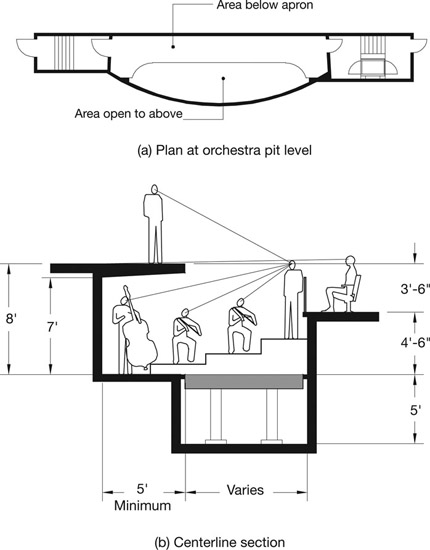
The pit should extend at least five feet upstage of the apron edge, to accommodate the exit doors and provide maneuvering room for wheelchair users.
Covered Versus Open Area
The covered pit area can extend up to 16 feet beyond the apron edge, but it’s usually no more than eight feet deep. In theory, the open portion of the pit can extend as far into the auditorium as needed. Acoustician Mark Holden suggests that 75 to 80 percent of the pit area should be open, though of course this figure will vary if the size of the open portion is adjustable. Maximizing the open area will reduce the musicians’ noise exposure (see sidebar), but will make balance between the singers and orchestra more difficult. Of course, it’s imperative to keep the first row of audience close to the performance on stage, not separated by an overly large pit. The pit should be as wide as the geometry of the auditorium allows, so that its depth can be kept to a minimum.
Musician Noise Exposure
Pit musicians are exposed to high noise levels and potential associated health risks. (By “noise” we mean unwanted sound—even music can be “noise” if the sound pressure level is too high, all aesthetic judgments aside.) Exposure varies with venue, repertoire, the instrument played, and the duration and frequency of rehearsals or performances. Time-weighted exposure levels are developed using a stipulated exchange rate—for each doubling of the duration of exposure, the sound pressure level is increased by the exchange rate. An exchange rate of three decibels (dB) is used internationally and is now recommended by the US National Institute of Occupational Safety and Health (NIOSH), but OSHA’s regulations are based on an earlier five dB exchange rate. OSHA stipulates a permissible exposure level (PEL) of 90 A-weighted decibels (dBA) and requires employers to operate a “hearing conservation program” at exposures of 85 dBA or more. The European Union Noise at Work Directive 2003/10/EC requires risk assessment and employee training at 80 dBA, more active measures at 85 dBA, and stipulates a PEL of 87 dBA. Multiple studies have found that musicians are exposed to levels of 80 dBA or higher—a 2004 study of Canadian Opera Company musicians found an average exposure level of 80 dBA, ranging from the trumpet at 84 dBA to the conductor at 74 dBA. Noise reduction has become a more prominent concern as the EU directive has been implemented in member nations.
Sightlines and Floor Elevations
Sightline requirements will affect the pit geometry and, for very small ensembles, may determine the pit size. The audience must be able to see the stage over the heads of the orchestra members. For opera, it is highly desirable that the audience sees the conductor. The conductor must see the stage floor, the dancers’ footfalls, and the singers’ faces. The singers must see the conductor.
Combined with the requirements for pit access above, the sightline constraints place the floor of the orchestra pit eight to nine feet below the stage floor, and require that the conductor stand on a two to three-foot high podium. An eight-foot floor-to-floor dimension is possible, if the apron floor slab is kept as thin as possible and the minimum code-required head height is provided in the covered portion of the pit. Maintaining the required head height also requires careful coordination of the elements mounted to the underside of the apron slab: sprinklers, lighting fixtures, acoustic absorption, electrical outlets, and probably a video camera focused on the conductor.
The conductor and the instrumentalists must also have line of sight to each other, and each musician’s angle of view to the conductor’s baton and face must not be too steep. One solution to the latter issue is to seat the musicians closest to the conductor on podiums. The next row may be seated on lower podiums, and so on, resulting in a reverse slope within the pit.
Why not set the fixed pit floor lower and build up as needed with adjustable height platforms to provide more flexibility? This is done in some venues, but the difficulty with this approach is maintaining the required wheelchair accessibility.
Production Video
Production video is often used in addition to direct line of sight between the conductor and the stage. Images of the conductor are displayed on video monitors above the forestage entrances, as mentioned earlier, as an aid to the performers on stage. The conductor will have a monitor displaying the action on stage, and the images of the conductor and stage action will be distributed throughout the production areas as needed.
Recently, some Broadway producers have moved the orchestra out of the pit entirely. For example, the 18-member “pit” orchestra for Spider Man: Turn Off the Dark performed from two rooms in the basement of the Foxwoods (now Lyric) Theatre. Of course, if the conductor and orchestra are located remotely, they and the singers must rely entirely on the audio and video feeds for communication.
Pit Cover
For venues with pits, the simplest way to add a measure of flexibility is a pit cover—that is, a demountable platform system that fills the open pit area when it is not needed. The platform can have adjustable or changeable supports, so that the pit floor can be raised to auditorium floor level for additional seating or to stage level to provide an extended apron. Sled-based auditorium chairs or ganged, portable chairs are used for audience seating on the pit cover. The platform system can also be designed to create a smaller orchestra pit or apron extension, with the remaining portion of the pit converted to audience seating. Each configuration will have vertical openings which must be protected by demountable railings or fascias. The advantage of a pit cover is that it provides flexibility at a low initial cost. The disadvantages are the time and labor required to change the pit configuration, the possibility of injury when changing the configuration, and the need to store system components that are not being used.
Pit Lifts
The mechanized pit lift is another method of adjusting the floor level of the open pit area. A pit lift has a much higher initial cost, but its lower operating cost and greater flexibility make it the preferred method. It consists of a guided, steel-framed lift table supported by lifting columns within a partially open hoistway. In a simple arrangement, the lift table has stops matching the covered pit level (for use as an orchestra pit), the auditorium floor level (for additional seating), and the stage level (for an extended apron).
The lift table can be set at any intermediate elevation, so it can be used to adjust the floor level of the orchestra pit—for example, to create a shallow pit for Baroque opera. Of course, this creates an elevation change between the open and closed portions of the pit and limits accessibility for musicians using wheelchairs.
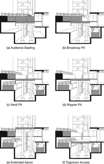
If more than one lift is provided, the lift tables can be adjusted individually to alter the size of the orchestra pit or apron extension. Or the lifts can be used to create a stepped floor within a larger pit. Many variations are possible. If the project can only afford one lift, the lift can be sized for the smaller pit and a platform system used for the larger pit, on the assumption the larger pit will be used less frequently. A flexible arrangement with multiple pit sizes and a single lift is also possible, as shown in Figure 10.3 and discussed further below.
Lifting Mechanisms
The mechanism that moves the lift table takes up space, requiring a machinery pit about five feet below the lowest usable stop. In older theaters, the lifting columns are probably screw jacks or hydraulic cylinders which extend from caissons sunk below the machinery pit. Most recent installations use either of two clever technologies that do not require caissons. One is a steel chain that forms a rigid lifting column. The other is called a helical band actuator—picture a Slinky combined with a watch spring to form a spiraling I-beam into a column.
Guide Columns
The lift table is stabilized laterally by shoes riding in vertical guide columns. Most lifts require two guides, and their position is dependent upon the shape of the lift table. The shoes are often bracketed down from the lift table, so that the guide columns (mostly) remain out of audience sight.
Service Access
When the lift table becomes disabled at one of its higher stops, the lifting mechanism is accessible from the levels below. This isn’t true if the lift table is disabled at its lowest stop, so a service access hatch is provided outside of the lift table footprint (preferred) or within the lift table itself.
Material Transport
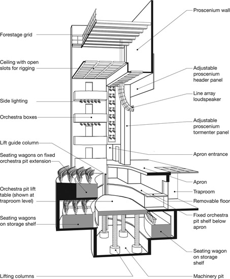
Most pit lifts are not intended to transport people, but they are handy for moving scenery and equipment between the stage and traproom levels. The traproom is almost always lower than pit level, so this use requires an additional stop and a lower machinery pit. Since the pit floor below the apron sits between the lift table and traproom, a portion of this floor must be removable to create a passage. When not in use, this passage is covered over with a removable platform. This arrangement is shown in Figures 10.1 and 10.3.
Seating Wagons
If the lift table will frequently be used for audience seating, then seating wagons are attractive timesavers. A seating wagon (or chair wagon) is a framed, rolling platform on which auditorium chairs are permanently mounted. The wagon is stored on a “shelf” below the fixed audience seating or stage apron. To deploy the seating wagon, the empty lift table is lowered to the storage shelf. The wagon is rolled onto the lift, aisle lights are connected, and the wagon is locked in place. Finally, the lift table is raised to auditorium level. The process is reversed to store the wagon. A small lift may hold a single wagon, but more often the lift area is divided into two or three seating wagons.
High Wagons
Orchestra pits of differing sizes can also be created with high wagons on a single lift, as shown in Figure 10.3. The wagons are designed to match the auditorium level when the lift table is at the orchestra pit stop. This approach saves the cost of multiple lifts, but it provides only one size for the extended apron, as shown in Figure 10.3e.
In many theaters, the very largest pit size—suitable for operas by Wagner or Strauss—is infrequently used. One way to accommodate the few productions that will use a pit of this size is to create a fixed pit extension on the downstage side of the open pit. The auditorium floor over this extension is built up with platforms or seating wagons that can be removed on the occasions when a very large pit is needed.
Air Supply
The “high wagon” approach described above is especially attractive when combined with displacement ventilation in the auditorium. Displacement systems supply fresh temperate air at low velocity through grilles located below the auditorium chairs. The stale air is extracted high in the auditorium. In this approach, the seating wagons function as plenums: they’re fed by ducts from the main plenum below the fixed seating, and they supply air to the patrons seated on the wagons. When the wagons aren’t deployed, the supply air can be diverted to service the orchestra pit through perforations in the lift table.
In a conventional system, cool air is supplied high in the auditorium and extracted low in the room. The patrons on the chair wagons do not require special provisions. Return air grilles in the orchestra pit draw air from the auditorium. Unfortunately, the air reaches the musicians at its stalest. The return grilles in the pit also cause low-lying fog effects to roll off the stage apron into the orchestra pit—this is perhaps good for the audience, but not for the musicians!
Protecting Openings and Edges
For the lift to serve its function, most of its hoistway must be open—that is, not enclosed by walls. This creates multiple vertical openings and edge conditions that must be protected. (For the sake of clarity, the illustrations in this chapter do not show the demountable railings that protect these openings.)
Stage Riser
Vertical openings are protected by fixed railings where possible. For example, the stage riser is Figure 10.3a is formed by fixed railings on the seating wagons, and the stage riser in Figure 10.3e is formed by a fixed fascia panel on the pit lift.
Orchestra Pit Rail
The orchestra pit is separated from the audience by a railing, typically 30 to 36 inches high so that it does not block sightlines and sound. If the pit size is fixed, the railing can be, too—perhaps with removable gates to allow access to seating on the orchestra pit cover. If the pit is adjustable in size, the railing is demountable so it can be placed at the first row—whichever row that is. This railing is a complex design challenge. It must function as a guard to protect audience members from falls. The acoustician may require specific acoustic properties. The sound designer may need front fill loudspeakers built into the railing. The architect will be concerned about the appearance and structural soundness of the railing, while the theater planner will insist it be not-too-heavy to lift and not-too-difficult to move!
Guards at Pit and Wagon Storage Levels
The openings at the orchestra pit and wagon storage levels are protected by utilitarian demountable rails, sometimes with chain or cargo netting instead of horizontal rails. All shear conditions, where the lift table passes an exposed floor slab, are protected by astragal safety switches. The lift controls incorporate interlocks so that the lift cannot be moved unless the protections described above are in place.
The “Throat”
Let’s return to the stage apron and look at the side walls, shown in Figure 10.1. Earlier we noted the forestage entrance, the side lighting position above the entrance, and the seating box at stage level.
Audience Seating
Perhaps there are several seating boxes, stacked vertically as in our figure or stepping down from the balcony (or balconies) to the stage. The boxes provide order and scale to the side wall of the auditorium, and place audience members where other patrons can see them. We’ll discuss this more in later chapters, but we note here that seating is one of several functions of the side walls.
Side Lighting
Side lighting positions in the auditorium are called “box booms” because, when electric spotlights were first used, they were mounted on vertical poles (booms) placed in the seating boxes. In new facilities, side lighting positions are better integrated and don’t displace audience seating. Often, however, the top level of boxes is not intended for seating but is a technical area.
Rarely is an effort made to conceal the spotlights—or the loudspeakers, infrared transmitters, video monitors, scenic projectors, and other gear that is part of a production. It’s impossible to predict the great variety and quantity of equipment that a production team will bring into the auditorium, and any pre-emptive attempt at concealment is doomed to failure. Instead, the design team focuses on well-designed accommodation for the production gear, ensuring that the accommodation itself is integrated and unobtrusive.
In addition to the near box boom above the forestage entrance, the stage lighting designer will need side lighting positions further into the house. If side wall geometry won’t accommodate a second vertical far box boom, then each seating box or gallery will incorporate a horizontal spotlight rail.
Reflective Surfaces
The acoustician will be concerned with the position and shape of the side walls and the size and treatment of the openings in these walls. Near-parallel, solid walls at the front of the auditorium are preferred for early acoustic reflections to the center of the main floor seating. The underside of box and gallery floors can also provide useful reflections. Splayed side walls kick sound to the back of the house where it’s buried and doesn’t contribute to the overall room acoustic.
If acoustic music is an important use, the acoustician may argue for large reflective areas of side wall that are uninterrupted by boxes, galleries, or other encumbrances. These open areas promote the multiple reflections between the side walls which develop the reverberant room acoustic. The theater designer will likely prefer audience seating over blank wall, for reasons we’ll discuss in Chapter 14. This is an area where the acoustician and theater designer must balance their respective objectives.
Acoustically reflective surfaces are also needed above the forestage. These could be reflectors hung within the auditorium volume, a hard ceiling of appropriate shape and height, or a utilitarian reflector that is concealed above a perforated metal or other type of sound-transparent ceiling.
Forestage Rigging
Many theaters have some form of forestage rigging to suspend loudspeakers, lighting trusses, or scenery downstage of the proscenium wall. In rooms for music, the acoustic reflectors over the forestage may be hung on rigging so that their elevation and angle can be adjusted.
Rigging accommodation over the forestage may be as simple as structural “strong points” designed for attaching chain motors, or as elaborate as a forestage grid. The latter is a walkable, structural steel floor similar to the gridiron above the stage. The forestage grid supports fixed winches for acoustic reflectors, loudspeaker clusters, and similar permanent loads. And it accommodates chain motors or winches for temporary production loads. Multiconductor electric cables may be dropped from the forestage grid to lighting trusses suspended below.
The rigging lines and electric cables must pass through any acoustic reflector or ceiling plane below. If possible, open slots in these surfaces are aligned with the spacing of the forestage grid wells. If slots are not possible, a pattern of holes is created, with each hole accommodating a winch line, chain motor hook, or electric cable.
In some facilities, the loudspeaker clusters can be stored above the ceiling, out of the audience view. This requires an opening in the ceiling and/or acoustic reflector above the forestage, and these openings may have motorized doors. At Overture Hall, this opening in the perforated metal ceiling is closed with a hinged panel, and the opening in the acoustic reflector above the ceiling is closed with a heavy panel that slides horizontally like a car sunroof.