
Chapter 15
Technical Elements
This chapter discusses the technical elements required in and around auditoriums for live performance—control rooms, sound mix positions, followspot rooms, and positions for spotlights. The types and sophistication of these accommodations will vary depending on the venue type and the anticipated performances.
Control Rooms
Control rooms (also called control booths) are enclosed spaces, usually at the rear or sides of the auditorium, used to house production equipment, the equipment operators, and other running crew. Most performance spaces will have at least one control room, and some spaces will have several dedicated to specific uses.
Uses
The primary purpose of a control room is to provide an acoustically isolated space in which the crew can operate production effects and ancillary services during the performance. The most common production uses are control of lighting, audio, and projection. The stage manager (who provides overall coordination of the performance) may operate from a control room or from the stage. Ancillary services performed in control rooms include surtitling (also called supertitling), recording, broadcast, captioning services for the deaf, and audio description of the visual elements of a performance for the blind. Venues designed for highly produced shows, such as a Cirque du Soleil spectacular, may have additional control functions: show automation (or show control) for the control of rigging and other stage machinery, moving light control, and control of special effects including air, mist, fog, smoke, flame, or pyrotechnics. Typically, each function or service occupies a dedicated work station outfitted with the needed infrastructure and equipment. These stations may be combined into one control room or distributed among multiple control rooms.
At the other end of the spectrum, some concert and recital halls do not have a control room at all, and the production elements are instead controlled from a position offstage of the concert platform.
Size
The width of each work station should be sized for the equipment required, but a minimum of four feet per work station should be provided. A room depth of 12 feet is desired, and 10 feet should be considered the minimum.
In addition to the run-time uses, most control rooms will also function as workrooms and storage areas, and control rooms in an educational setting are often used as classrooms. These secondary uses may require more floor area than the primary use.
Location and Access
The control room must be accessible from the back-of-house circulation outside of the audience’s view, and if possible it should also be accessible from the auditorium, for convenience during rehearsals. The location should provide sightlines to the performance area for both sitting and standing crew members, and these sightlines should not be blocked by standing spectators. In addition, the control room must be accessible to persons in wheelchairs.
Given these parameters, the most prevalent location is at the rear of the main level of the auditorium. The control room is often inserted between the lobby and the auditorium, with access from the auditorium sound and light locks. To provide adequate sightlines, the room is usually a few feet higher than the last row of seating, and this often requires a platform lift, since a ramp would take up too much room. If the auditorium has multiple levels, the upper sightlines from the control room may be limited by the first balcony overhang. This location has another potential disadvantage, especially if the building site is constrained: there may be pressure to reduce the control room depth, so that this dimension can be used instead for more rows of orchestra seating, a deeper stage, or a bigger lobby.

It therefore sometimes makes sense to place the control room at an upper level, where sightlines to the performance area may be improved and a larger footprint may be possible. The main disadvantages of a higher location are that the room is less convenient to the auditorium, and upper sightlines into the stagehouse may be constrained. In a very few theaters the control room is located in a back-of-house area where it doesn’t have a direct view of the stage and the operators are dependent on audio and video monitors.
Configuration
A performance space with modest needs may have a single control room. This allows one operator to perform all required functions for a simple performance.
If many workstations are required, it’s likely that the control room will be subdivided or that multiple control rooms in different locations will be provided. The advantage of a subdivided room is that all functions and personnel are in one location and circulation can be shared. Subdivided rooms can be acoustically separated so that a sound operator, say, can work with an open window into the auditorium while the stage manager can work with a closed window. Providing vision panels in the partitions that subdivide the room allows for nonverbal communication between operators, which can be helpful. The advantage of multiple rooms (as opposed to one, subdivided room) is that they may be better located for their specific functions and there may be more floor area available if the rooms are distributed.
Sightlines

The observation window into the auditorium must be located and sized to provide sightlines for an operator seated at a control desk. Often this means the sill must be lower than a typical counter height. If the control room is at a high elevation, and the sightline is steep, it may be necessary to orient the control desks perpendicular to the observation window in order to maintain sightlines. Sightlines should also be provided for a standing crew member, and the combination of this with a low sill may require the window to be quite large.
When closed, the observation window must provide reasonable acoustic separation from the auditorium, to allow the operators to give and respond to verbal cues. The window should also be operable, to allow communication between the control room and the auditorium without dependence on monitor and intercom systems. This is especially helpful during rehearsals and work calls. The window of the sound control room must be operable to allow, as much as possible, the sound operator to experience the aural environment within the auditorium. At minimum, the sound operator should have a 4-foot by 4-foot open window. For live mixing and other demanding tasks, the sound operator will be placed within the auditorium in an open mix position.
Sound Mix Position
If live audio mixing is an important part of the performance, it will be performed from an open position (or cockpit) within the auditorium, rather than from an enclosed control room. Concert halls, multipurpose theaters, and venues intended for musical theater almost always have live mix positions, and many other types of venues do as well.
Use
The mix position houses the audio mixing console and any related outboard equipment in a location that exposes the operators completely to the aural environment of the auditorium, so they can better perform the sound mix. In some venues, the mix position may house additional functions—for example, a moving light console, show automation, teleprompters, broadcast control, or cameras.
Location
Locating the mix position is a question of balancing competing priorities. The sound operator’s preferred location is within 75 feet of the stage, on or near the auditorium centerline, and within range and view of the main loudspeakers. Locations close to a side wall or under a balcony overhang are not desirable, as they may distort the operators’ perception of the sound. A prevalent location is at the center rear of the orchestra seating, just in front of the balcony overhang (if there is one). A mix position here will displace highly desirable seats, however, and could disrupt the enjoyment of patrons seated nearby. For these reasons, there is sometimes pressure to move the mix position further back, under the balcony overhang, or to the side of the room.
Size
The position is sized to accommodate the mixing console and its outboard gear and to provide room for the operators. Depending on the needs of the venue, the mixing console may have a footprint as large as 6 feet wide by 4 feet deep. Touring productions will bring their own mix console, and it will likely be necessary to remove the house console in order to provide space for the touring console. Providing space for both would result in a very large mix position. Of course, if other equipment and operators will use the cockpit, then space must be provided for them too. A starting point for a concert or touring venue is to provide a mix position that is at least 12 feet wide by 10 feet deep. This displaces about three rows of seven chairs for a total loss (or “seat kill”) of 21 chairs. A good starting point for a drama venue is to provide a space that’s 9 feet wide by 6 feet deep. This displaces about ten chairs.
Access
Discreet access to and from the mix position is desirable, but personnel access is usually through the public circulation within the auditorium. Access for equipment is of greater concern. In addition to being large, mixing consoles can weight up to 500 pounds, so moving consoles is not an easy task. Touring venues must have a path from the loading dock to the mix position that does not have steps, steep ramps, or tight turns. Sufficient space must be provided at the mix position to allow the con sole to be set in place without damage to nearby auditorium chairs, for example.
Sightlines
The equipment operators within the cockpit must have clear sightlines to the performers and to the main loudspeakers. Audience members seated behind the mix position must have clear sightline over the operators’ heads. This is often accomplished by depressing the floor of the mix position, and having the operators stand or sit on high stools. If the mix position is immediately in front of the parterre rail, the first row of the parterre can be elevated sufficiently to provide audience sightlines over the operators’ heads.
Of course the mix position itself is within the view of the audience members behind it, and light and noise from the mix position can distract from the performance. A permanent mix position can be separated by knee walls, and temporary positions are often draped in black velour, to minimize the distraction.
Configuration
The sound mix position can be permanent, demountable, or provided with a lift and wagons.
Permanent
Some venues opt for a permanent sound cockpit. This has the advantage of being always available, and it can be better integrated into the design of the auditorium, with knee walls, railings, or other millwork as appropriate. The disadvantage is that the seats displaced by the position are not available for those performances that don’t require a live mix, so the venue forgoes this potential income.
Demountable
A demountable position allows the sound cockpit to be transformed into audience seating when a live mix isn’t needed. A platform system is used to cover the pit recess, and sled-mounted auditorium chairs are brought in and fastened to the platforms. The disadvantages of this approach are the ongoing labor costs to change over the position, the need to store the platforms, chairs, and equipment items when they are not in use, and the wear and tear on these items and the area surrounding the mix position.
Lift and Wagons
The best solution is to provide a lift and wagons for the sound mix position, similar in configuration to the orchestra pit lift and seating wagons discussed in Chapter 10. See Figure 15.3 for an illustration. In this option, a sound cockpit lift travels between the auditorium level and a storage and work level below the auditorium. Two wagons are provided—one for seating and one for the house mix console and its auxiliary gear. The changeover between uses involves lowering the lift, removing one wagon, moving the other wagon into place, and raising the lift back into position. The wiring can even be arranged so the house console does not have to be unplugged and
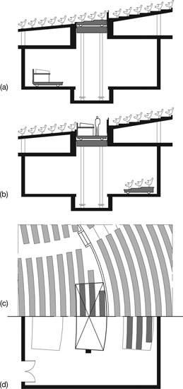
Figure 15.3 Sound Cockpit Lift and Wagon Arrangement. (a) Section showing audience seating wagon in place. (b) Section showing sound cockpit wagon in place. (c) Half plan at auditorium level with seating in place. (d) Half plan at wagon storage level
Source: Author
replugged. When a touring company arrives, the touring console is brought to the level below the auditorium. Both wagons are moved to storage, and the touring console and related gear are set up on the lift table and raised into place. Of all the options, this has the highest first cost, but given the ongoing expense of the demountable solution and the lost ticket revenue of the permanent solution, it may have the lowest lifetime cost.
Followspot Rooms
Use
A followspot is a large spotlight that is manually directed at a performer, and a followspot room (spot room, spot booth) is an enclosed and acoustically isolated space for followspot operation. Not all venues have followspots, and not all followspots are operated from acoustically isolated rooms. The most common use is in musical theater and many forms of popular entertainment, where followspots are used to provide front light. They focus attention on the lead performers, and are not meant to provide naturalistic lighting.
Location and Access
For this use, the spot room is located on the centerline of the auditorium, at a distance and height that provides an angle of light between 30 and 40 degrees above horizontal to a performer standing at the plaster line. Placing the room on centerline means each of the followspots housed there can provide the same coverage and angle of light, since the distance between the spots is negligible relative to the throw distance. The required lighting angle means that most followspot rooms are located at an elevation higher than the general building circulation, and it’s typical for a spot room to be accessible only from the technical catwalks above the auditorium. Followspot rooms are considered “limited access spaces” under the ADA and are not required to be accessible. A reasonable loading route must be provided for the equipment, however. Like audio mix consoles, followspots can be bulky and heavy.
Size
The room should accommodate at least three followspots—one each for the hero, heroine, villain—and more if the intended performances will require them. The space should be provided, even if the followspots are not, as it’s common practice to rent followspots for specific productions. The floor area needed will depend on the size and type of followspot, and this depends primarily on the throw distance to the stage. A good starting point is to provide 6 feet of width and 12 feet of depth for every followspot.
Sightlines
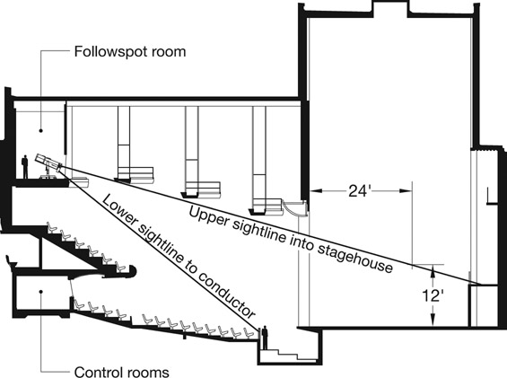
The followspots must have a range of motion and unobstructed sightlines allowing each spot to light any part of the performance area. At a minimum, the lower sightline should reach the conductor in the orchestra pit, and the upper sightline should reach 12 feet above the stage floor on a backdrop hung 24 feet from plaster line. These sightlines are illustrated in Figure 15.4, and the corresponding plan is shown in Figure 15.6.
To provide these sightlines, the observation window typically consists of large panes of glass, about 5 feet high by 6 feet wide, with silicon butt joints. Mullions are avoided if possible. Each pane is single-thickness, low iron, tempered float glass. Laminated glass is not used. The glass extends almost to the floor of the room—it’s useful to have enough space for an electric wireway at the base of the window. Provision should be made to allow cleaning both sides of the glass.
Other Uses
In opera and some other productions, soft-focus followspots may be used more subtly to both highlight and provide three-dimensional modeling of the performers. In addition to the front followspots, additional units may be located at the sides of the auditorium or above the stage, but these additional followspots are seldom in enclosed rooms.
Front-of-House Lighting Positions
In addition to a followspot room and the side lighting positions discussed in Chapter 10, the stage lighting designer and electricians will need positions in and above the auditorium for mounting spotlights to light the stage. The positions integrated with the auditorium ceiling, or hung below the ceiling, are called by various names, including beam, cove, slot, and catwalk. We’ll use catwalk for simplicity. The positions incorporated on the front faces of the balconies are called balcony fronts or balcony rails. Collectively, the catwalks, balcony fronts, and side lighting positions are called the front-of-house (or FOH) to distinguish them from the lighting elements on and over the stage.
Catwalks
Front light is typically organized in zones that span across the width of the stage, with each zone lit by multiple spotlights. When planning the catwalks, our first concern is the vertical angle of the lighting. Each zone, from the apron edge to the rear wall, should be lit from approximately the same angle above horizontal. At the front part of the stage, this angle is dependent on the number of catwalks and their locations.
Locations
To determine the optimal locations, a centerline section of the auditorium is drawn, as illustrated in Figure 15.5. To begin, set the center of the first zone four feet back from the stage riser. Draw a work plane (the surface to be lit) five feet above the stage floor. This will focus the light on the head and upper torso of the performer. Next draw lines from the center of the zone at the desired front lighting angles. The most important angle is about 45 to 50 degrees above horizontal. (If the project can only afford one cat walk, it should be located to provide this angle of light. But, feeling confident we can afford multiple catwalks, let’s continue our exercise.) The next most useful angles are bracketed above and below the first angle, say at 25 to 30 and 60 to 65 degrees above horizontal. If we’re feeling really confident about the budget, we might also draw a top light, at 80 to 85 degrees above horizontal.

Next, draw these angles for a second zone centered about eight feet upstage of the first. We don’t need to draw a third upstage zone, as that will be covered by the lighting battens above the stage. But if there is an orchestra lift or a demountable forestage, we need to draw a forestage zone about eight feet downstage of our first zone. We now have three zones and potential locations for nine catwalks. This is clearly too many! If we have a sketch from the architect of the proposed ceiling profile, we can overlay our diagram on the sketch and begin to work out catwalk locations that rationalize the lighting angles and work with the ceiling design.
Figure 15.6 illustrates the end result of this process. We have located four catwalks that together provide three lighting angles to each of our three zones. (Note that the fourth catwalk isn’t continuous, as it’s interrupted by the followspot room. Also, the steepest angle to the upstage zone is actually provided by the first lighting batten over the stage.) The angles are consistent within a tolerance of ± four degrees—an acceptable level of compromise.

Width
We now turn our attention to the lighting angles in plan. A catwalk that is the width of the proscenium opening may be adequate for straight-on front light, often called a “wash.” A wider catwalk is needed for “area lighting”— this is front light from each side, typically at a 45-degree angle from the centerline. Catwalks should extend across the full width of the auditorium in order to provide consistent lighting angles to the full width of each zone. If this is not enough width to provide a 45-degree lighting angle to the near side of the stage, then those spotlights are moved to a side lighting position instead.
Contour
We’re also concerned about the contour of the catwalks in plan and elevation. A catwalk that is level and perpendicular to the auditorium centerline functions best, but catwalks must often be shaped differently to accommodate the ceiling design. The slight curve in our example is not problematic, and tighter curves and reverse curves are possible. Catwalks may also slope up toward the auditorium centerline, or both curve and slope. In these cases, the theater planner and architect collaborate to ensure that the catwalks are safe to use and provide the necessary range of lighting angles.
Balcony fronts
Each balcony face presents another opportunity for a front lighting position. Of course, the balcony locations aren’t determined by the needs of the stage lighting designer, and their utility as lighting positions will vary. The front of the first balcony is used most. For Broadway and other heavily produced shows the entire width of the balcony face may be filled with spotlights, scenic projectors, video cameras, and other equipment.
Elevation
Equipment mounted to the face of the first balcony affects both the upper sightline for the patrons on the main floor and the lower sightline for patrons in the balcony. The spotlight mounting rail is located so that the potential obstruction is centered between these two sightlines. Sightlines from higher balconies are steeper, and the mounting rail usually must be lower on the balcony face in order to keep the spotlights from interfering with views of the stage. A lower mounting rail can place the spotlights out of reach, however, making it difficult or impossible to service the spotlights.
Width
Architects sometimes prefer to minimize the width of the balcony front mounting rail, and for venues with modest needs, a 10 to 12-foot railing at the center of the balcony can be adequate. Other architects prefer a continuous mounting rail that can be incorporated into the balcony front design, and from a functional viewpoint this approach is preferred.
In some venues the mounting rail is continued along the faces of the galleries or boxes at the sides of the room, providing a side lighting position. If the balcony has a tight curve or the room is narrow, this mounting rail may obstruct sightlines from the ends of the balcony rows and from the galleries or boxes. If this is the case, the center rail is cut short, and the side rails are moved below the gallery or box fronts.