
![]()
Printing for the First Time
At this point, you either have a new 3D printer1 or you have just finished calibrating the hardware of the printer you’ve built yourself. Either way, you are now looking at the exciting possibilities of printing your first object. To get the most out of your printer and indeed your first printing experience, you need to take some time to prepare your printer. Yes, there are still more things you need to work on—even for a printer right out of the box. While this sounds like more tedious procedures and fiddling, that isn’t the case.
This chapter begins with the steps you need to take to ensure that your printing surface is prepared properly. This is an essential step to ensure that you eliminate yet another source of problems that can masquerade as other problems. A properly prepared print surface can help you avoid contributing to one of the worst and most frequent printing problems—lifting.
The chapter also presents tips on preparing your slicer and printing your first object. In this case, I discuss starting out with simple calibration objects that can help you fine-tune your printer. You will see how to use simple geometric shapes (e.g., cubes) to ensure that your printer is calibrated correctly. Let’s get started!
Preparing the Printer for Printing
There are certain things you need to do before you print. Whether it is the first time you’ve printed with a new printer or the hundredth object on a well-maintained printer, there are certain steps you need to do before you power on the printer.
This is one area that most 3D printing books skim over or mention in a few sentences. However, taking time to get your printer prepared will save you from a host of printing problems. There are three preparation tasks you should perform prior to printing: you should ensure that your print surface is prepared and the preparation matches the filament type you want to use, you must set your Z-height, and you must ensure that your slicer settings match your filament requirements for temperature and diameter.
I present each of these in more detail in the following sections. Once you have taken the time to execute these steps, you will be ready to print.
Preparing Your Print Surface
There are several types of print surfaces. The filament type dictates which of these you can use. For example, recall from Chapter 1 that the best surface for PLA is blue painter’s tape, and the best surface for ABS is Kapton tape. These are surface treatments that work best for PLA and ABS filament. I will discuss one alternative for ABS that is used to combat lifting.2
There are some additional considerations if you have a printer that permits you to choose the print surface itself. For example, aluminum is better for using blue painter’s tape, and glass is a good choice for Kapton tape. However, glass works well for both.
The following sections present various surface treatments. I include notes about the surface so that you can consider which is best for your needs.
![]() Tip I like to have a different print surface for each surface treatment. For example, I have one for blue painter’s tape, another for Kapton tape, and a third for Kapton tape plus ABS juice (see the following sections).
Tip I like to have a different print surface for each surface treatment. For example, I have one for blue painter’s tape, another for Kapton tape, and a third for Kapton tape plus ABS juice (see the following sections).
Prerequisites
To get the most out of your surface treatment, you should ensure that the surface is clean and free from any dirt, smudges, and oils from your hands, and that it is dry. If your print surface is glass or aluminum, clean the surface with acetone followed by 90% or better isopropanol, which cleans the surface well— without leaving any residue like soap and other cleaners. You may also use window cleaner, but make sure that it is safe to use on your print surface first. If you use a water-based solution, make sure that it is completely dry before printing.
If you are replacing the surface treatment, make sure that you remove all of the old treatment first. Using several layers of surface treatment—more specifically blue painter’s or Kapton tape—is not recommended. Figure 6-1 shows what can happen if you use blue painter’s tape on top of Kapton tape. While it saved me from having to remove the Kapton tape first, it created a lifting problem because blue painter’s tape does not adhere well to Kapton tape. The same is true for multiple layers of the same type of tape.

Figure 6-1. Multiple layers of surface treatment
Blue Painter’s Tape
If you visit your local hardware or home improvement store, or even a specialty paint store, you will find a number of tape products that are specifically designed to be used to mask out areas for painting (also called masking tape). The best tapes for painting are those that prevent paint from bleeding along the edge, which helps painters create precise lines when painting with multiple colors or around trim, electrical components, and just about anything they don’t want painted.
There are several types of painting masking tape. Some are nothing more than common masking tape (tan or brown in color), others are blue, while others are a combination of tape and plastic sheeting.3 While some are certainly better than others, they all have one attribute that is a must for painters: they can be removed easily without peeling away the paint or wallpaper to which they were adhered. The type of tape we will use is called blue painter’s tape. We call it that because, well, it’s blue and it is used for painting.
GOT THE BLUES?
There are some new vendors making painter’s tape, and some of these are not—gasp!—blue! Indeed, I have found green and yellow painter’s tape—called FrogTape. The green is equivalent to typical blue painter’s tape. The yellow is a low adhesion version for sensitive surfaces. Some people have reported mixed results with the green tape. I have found it works OK with a heated print bed, but it is not as good as blue painter’s tape without a heated print bed because parts do not stick to it as well. However, the yellow is not as good for 3D printing because it can become loose and pull off with the part.
Blue painter’s tape is a very good surface material for print beds. It works well for PLA and can work fine for ABS if a heated printed bed is used (but not as good as Kapton tape for ABS). The tape comes in a variety of widths and can be applied to glass or aluminum easily, and can be removed and replaced quickly without special applicators or tools.
![]() Note Objects printed on blue painter’s tape will have a matte finish for the bottom and will show the stippling of the tape.
Note Objects printed on blue painter’s tape will have a matte finish for the bottom and will show the stippling of the tape.
Parts can be removed easily once they have cooled, and the tape can be reused a number of times. Due to its lower cost, removing parts is not a stressful affair, even if you tear the tape. You can just cut away one strip or a part of a strip and replace that portion.
![]() Tip Objects can be removed from blue painter’s tape more easily once they have cooled.
Tip Objects can be removed from blue painter’s tape more easily once they have cooled.
But not all blue painter’s tapes are created equal. I recommend avoiding the really inexpensive, little-known manufacturers. Some of these may be just fine, but if they do not adhere well to the print surface, it can make a lifting problem worse. Similarly, if they adhere too well, they may not be easily removed from the print surface, making it harder to replace the tape.
HOW WIDE IS WIDE ENOUGH?
In general, it is best to get the widest tape you can find. However, be sure to do some comparative shopping. For example, I once found some four-inch-wide blue painter’s tape, but it was priced nearly four times the cost of the two-inch tape and was only 75% as long as the two-inch rolls. In this case, wider is not cheaper. Also, really wide tape can be harder to apply if your print bed surface is not removable, especially if there are frames or electronics that prevent you from accessing the print surface easily. Thus, I use 2-inch-wide tape and make several passes to cover the entire surface. This, for me, is the most economical choice.
Another consideration is whether the tape has the manufacturer’s logo imprinted on the tape surface. You should avoid using these tapes if you plan to print with light-colored filament. This is because the logo can transfer to the filament. For example, I used a major manufacturer’s “best” blue painter’s tape for printing white PLA. When I removed my objects from the printer, I discovered the logo was prominently displayed on each of my objects. If you use dark colored filament, you may not notice, but I would still avoid tape that has logos imprinted on the surface.
You will have to do your own cost analysis based on the cost of the tape in your area, but generally, you should look for a balance of cost, width, and adhesive qualities. For example, I use two-inch-wide tape that features a nonbleed edge and does not have any logos. It costs a bit more, but makes for a good bond to glass and has a much better durability than cheaper brands.
Applying blue painter’s tape to your print surface is really easy. You simply cut a length of tape a bit longer than your print surface and apply the tape to the surface one row at a time until the surface is completely covered. Don’t worry about overhang—you can cut that away with scissors or a hobby knife after the surface is covered. I like to leave a bit of an overhang so that I can more easily remove the tape. But don’t leave so much as to affect movement of the printer axes. That is, blue painter’s tape overhang can curl on heated print beds. If you leave so much that it curls and strikes the hot end, it could stick and peel away the tape—or even obstruct the nozzle, causing extrusion failures.
The hardest part of applying the tape is getting the seams even and as close as possible. Fortunately, the tape can be removed easily, so if you need to adjust it, you can. I like to start by holding the length of tape just beyond the print surface or at least near the edge. Position one side of the tape so that there is no gap, and then slowly lower the other side, keeping the tape straight and tight against the edge of the previous strip. Again, this is easier to describe than do, but once you’ve practiced it a couple of times, you’ll get the hang of it.
Once I have the tape applied, I trim the edges and use a flat edge to press down across the seams. This allows you to firmly adhere the tape to the print surface, even if there is a small bit of overlap.
Figures 6-2 through 6-6 present the process for applying blue painter’s tape. I used a special milled aluminum print surface for a MakerBot Replicator 2. The procedure is the same for glass, nylon, and similar materials. The only possible deviation would be if your print surface is soft (like Plexiglas). In that case, you may not want to use a hobby knife to trim the edges. That is, if you slip and cut the blue tape, you may also mar the print surface.

Figure 6-2. Applying the tape in rows

Figure 6-3. Align one side first

Figure 6-4. Align the other side

Figure 6-5. Cut away the excess tape

Figure 6-6. Smooth over the gaps
In Figure 6-5, I apply the finishing touches of trimming the excess and smoothing the seams. If your tape overlaps, you may see the effect on the bottom of your prints.
Notice in Figure 6-3 that I pulled the tape taught and aligned the outer edges. This helps avoid creating wrinkles and ensures that the seam is even across the surface. Notice that I also left a little overhang.
![]() Caution Try to avoid overlapping the tape. The thickness of the tape may be enough to cause the nozzle to strike the tape on the first layer, which can lead to problems such as lifting, or at the very least a crease on the underside of your object. Similarly, avoid gaps between the strips of tape. Gaps will cause creases on the bottom of your prints, but can also lead to lifting if the filament does not stick to the build surface.
Caution Try to avoid overlapping the tape. The thickness of the tape may be enough to cause the nozzle to strike the tape on the first layer, which can lead to problems such as lifting, or at the very least a crease on the underside of your object. Similarly, avoid gaps between the strips of tape. Gaps will cause creases on the bottom of your prints, but can also lead to lifting if the filament does not stick to the build surface.
Printing with blue painter’s tape requires no special settings on your printer. So long as the Z-height is set correctly (the width of a standard weight sheet of paper), filament should stick to the tape easily. Blue painter’s tape is great for printing with PLA and can also be used for printing ABS if there is a heated bed (but this may be harder to control lifting). Using blue painter’s tape with PLA and a heated bed works equally well, however, it has known to reduce the effectiveness of the adhesive, so you may have to change the tape more often when using with a heated print bed.
![]() Tip Using blue painter’s tape with ABS requires a very precise Z-height setting. I have found I need to set the Z-height lower when using ABS on blue painter’s tape than Kapton tape. ABS doesn’t stick as well to blue painter’s tape as it does to Kapton tape.4
Tip Using blue painter’s tape with ABS requires a very precise Z-height setting. I have found I need to set the Z-height lower when using ABS on blue painter’s tape than Kapton tape. ABS doesn’t stick as well to blue painter’s tape as it does to Kapton tape.4
You should change the tape when you see distortions on the surface. After several prints (perhaps as few as five), you may also start to notice a change in the color of the tape. Some discoloration is fine, so long as the tape is still attached to the print bed. We are most concerned about any damage from removing parts or distortion of the tape surface, which can happen over many prints.
This is especially so if your slicing software positions the objects in the center by default. In this case, the center of the tape will wear out sooner. On the other hand, even if there is no distortion, if your prints start losing first-layer adhesion—or worse, you start experiencing lifting at the edges and corners, you should replace the tape.
If you used two-inch-wide tape like I do, you may be able to replace only a strip or two of the tape. That is, if you’ve only printed in the center and the size of the objects printed do not extend past the center two strips, just replace those. You do not need to completely strip the surface every time. This is also another good reason to choose tape that isn’t as wide as your print surface—you can replace only those areas that are worn.
Kapton Tape
Have you ever seen the inside of a modern laptop, tablet, or smartphone?5 Did you notice some transparent yellow tape in there? Most likely you were seeing Kapton tape. Kapton is a brand-name tape made by DuPont. Kapton tape is a polyimide film with an adhesive on one side. It is highly heat resistant across a range of temperatures from –269ºC to +400ºC (degrees Celsius). In the 3D printing world (and likely others), the name Kapton has become synonymous with the product (like Xerox). Indeed, you may find several vendors who sell polyimide film, but do not call it Kapton tape (for obvious trademark/product restrictions).
Kapton tape is best used for printing ABS. It may also work for other higher-temperature filaments. Kapton tape is more difficult to apply because the adhesive is designed to stick really well. In fact, the adhesive is stronger than the film itself. Thus, if you apply Kapton tape to a dry aluminum or glass print surface, you may not be able to remove it without tearing the film. Figure 6-7 shows a typical roll of Kapton tape.

Figure 6-7. Kapton tape roll
![]() Note Objects printed on Kapton tape will have a smooth finish on the bottom. Some don’t like this because it is different from the other sides of the object.
Note Objects printed on Kapton tape will have a smooth finish on the bottom. Some don’t like this because it is different from the other sides of the object.
Removing parts from Kapton tape can be a bit of a challenge. For the best results, you should wait until the parts cool completely before attempting to remove them. They remove more easily when cool. There are a number of techniques for removing parts from Kapton tape. Some are to use a sharp knife, or a craft blade, or a putty knife to pry the parts off. Any of these will work, but you risk damaging the Kapton tape. Given that Kapton tape is relatively expensive and harder to apply, you may want to use these tools as a last resort.
The technique I use for small objects is an adjustable wrench tightened around the object perpendicular to the print bed. I apply a slight force to the wrench to twist the object—just enough to flex it—and the object usually pops off, or that side pops loose enough for me to use a dull plastic blade to pop the object off the print surface.
![]() Caution Do not attempt the following without wearing thick gloves and eye protection. If you get this wrong, you can break your glass print bed!
Caution Do not attempt the following without wearing thick gloves and eye protection. If you get this wrong, you can break your glass print bed!
Another technique that works for objects that are really stuck to Kapton tape on normal glass is to remove the glass print surface and place it on a towel on a workbench or a desk. Move the print surface so that half is on the desk and half is not. Press down very softly, gradually increasing pressure until you hear a pop. Do not use quick, energetic pressure—this can break your glass print bed! Repeat this for each edge or until enough of the part is free for you to pry it off.
Like blue painter’s tape, you will find Kapton tape in a variety of widths. However, unlike blue painter’s tape, I prefer the wider widths because it is harder to get pieces to align well enough to avoid gaps or overlap. Once again, you have to do some comparative shopping, as the wider widths can be a bit more expensive than the narrower widths. I use 200mm width rolls and make two passes (two strips) when applying the tape. This leaves only a single seam down the center of the print surface.
Applying Kapton tape requires some practice and a fair amount of patience. I have found a technique that works well for most print surfaces. It works best for glass and aluminum. I would not recommend using it on porous print surfaces or in situations where you cannot remove the print surface (like the MakerBot Replicator 1). See the sidebar for special instructions on the Replicator 1. The technique I use is as follows. Figure 6-8 through Figure 6-13 show the process in action.

Figure 6-8. Getting ready

Figure 6-9. Applying the water mixture

Figure 6-10. Apply one strip at a time

Figure 6-11. Apply remaining strips until surface is covered

Figure 6-12. Go over the seam(s)

Figure 6-13. All done!
- Remove the print surface and place it on a flat, water-resistant surface. I like to put a couple of paper towels down first to absorb extra liquid.
- Use a mixture of 1 drop of baby shampoo to 4 ounces of distilled water.
- Spray a liberal amount of the water on the print surface. Use a spritzing sprayer to distribute the water as evenly as you can.
- Cut a long strip of Kapton tape that is at least 2 inches longer than needed.
- Spray a small amount of the water on your fingers and carefully grip the tape on each end.
- Hold the tape over the print surface and allow it to droop, forming a “U” shape.
- Slowly and evenly (without pulling), lower your hands so that the tape spreads out evenly.
- If the tape isn’t applying evenly, remove it and try again. The water solution will make the tape much easier to remove. Spray more water if the tape is sticking to the glass.
- Using a rubber or similar soft-edge squeegee, start in the center of the tape and press lightly and outward to one edge to squeeze out the water. Repeat for the other direction. If there are large bubbles or wrinkles, carefully lift the tape back to the point where the anomaly begins and reapply by pulling (but not stretching) to remove the crease.
- Continue to squeeze out all of the water you can. It is OK if you cannot get all of the bubbles out. Small bubbles (say, about 4mm–5mm in diameter) are fine and will disappear as the water dries.
- Repeat the process for the next strip, carefully aligning the tape next to the applied strip. You will find the water makes it easier to remove and even move the tape so that it joins the first strip.
- Use the squeegee to remove as much water as possible. Go over the seams again with the squeegee to remove water trapped near the edge.
- Use a hobby knife to cut off all the excess Kapton tape.
- Dry the print surface with paper towels, place the print surface in sunlight, and allow it to dry. Any small bubbles will disappear in a few hours or, at most, overnight.
![]() Tip It is fine to spray a lot of water on the surface. The water keeps the tape from sticking to the glass.
Tip It is fine to spray a lot of water on the surface. The water keeps the tape from sticking to the glass.
Starting in the center, use smooth even strokes to press the water out to the edges.
Try to get the strips as close together as possible. Overlap should be avoided. If you do leave a small gap, make sure that it is no more than a few tenths of a millimeter at most. Any more than that and you will get a ridge on any objects that cross the gap.
USING THE APPLICATION TECHNIQUE ON THE REPLICATOR 1
You can use the preceding technique on the MakerBot Replicator 1, but it requires more work and a fair amount of caution. You must first remove the print bed from the printer. This requires disconnecting the heated print bed (the connector is located in the center of the back of the print bed) and removing the four bed leveling thumbscrews. Once removed, you can lift the print bed off of the arms and out of the printer.
Carefully cover the heated bed connector with electrical tape or similar water-repellent tape. With the electrical connector covered, you can use the preceding technique to apply the tape. Try to use as little water mixture as you can to avoid filling the screw heads with water. Allow the print bed to dry overnight and inspect it for any traces of water. Never use the print bed if there is any moisture anywhere.
Clearly, this is a deviant procedure that solves the problematic dry application of Kapton tape for Replicator 1 machines, but it takes much more time since you must allow the bed to dry before using it and you must relevel the print bed when you reinstall it.
This is one reason why some owners have replaced their heated print bed with a removable version. If you own a Replicator 1, you may want to watch the online auction sites for an old heated print bed. Having two will allow you to keep a dry, prepared surface in reserve.
Printing with Kapton tape requires a very precise Z-height—more so than blue painter’s tape. You should check your Z-height for the first few prints on newly applied Kapton tape (if not at least once per day of use).
While ABS sticks very well to Kapton tape, it is not a cure for lifting. Some people have switched from blue painter’s tape to Kapton tape in order to solve lifting problems, only to discover it made it worse. This is most likely because the print surface wasn’t the problem. For example, if ABS is subjected to cooling air currents, the higher layers can shrink faster than the lower layers (which are heated by the print bed), forcing the lower layers to bend and curl—hence, lifting.6
![]() Note Delamination of layers can occur not only from cooling too fast but also when printing on a layer that has cooled. In this case, the temperature of the two layers is too low for a sufficient bond.
Note Delamination of layers can occur not only from cooling too fast but also when printing on a layer that has cooled. In this case, the temperature of the two layers is too low for a sufficient bond.
To get the most out of printing ABS on Kapton tape, you should use a heated print bed set to a range of 90ºC to 110ºC. The proper temperature may take some experimentation to get right and can vary based on the filament used. I have some lighter-color filament that requires lower heat on the print bed. The best thing to do is start at 100ºC and watch how well the first layer adheres. If there is some lifting on smaller-diameter parts or the edges, increase the heated print bed by 5 degrees and run another print. This isn’t a terribly scientific process. I tend to use 100ºC to 110ºC when I print with ABS on Kapton tape, using the lower range for large objects and the higher for smaller objects or objects with thin protrusions. You can set these values in your slicer program.
Replacing Kapton tape is required less frequently than blue painter’s tape. It is more likely you will damage the tape when removing objects before the adhesion properties degrade. Even then, you can revive Kapton tape by using a small amount of acetone and a lint-free cloth to remove any ABS from the surface. I have had Kapton print surfaces last for more than 40 hours of printing. In fact, I have yet to wear the tape out without first damaging it.
ABS Juice
If you are printing with ABS and want to improve your first-layer adhesion, or you don’t want to use Kapton tape (or you ran out), there is a surface treatment called ABS juice.7 You can apply it to glass or on top of Kapton tape.
Simply dissolve about 10mm–20mm of thin ABS scrap from discarded skirts, brims, rafts, and so forth (filament can take a long time to dissolve) per 10ml of acetone in a glass jar with a lid. To apply, spread the solution evenly on a glass surface, allow it to dry (it only takes a few minutes), set your Z-height, and start printing. This technique will significantly reduce lifting problems with ABS on Kapton tape and is a great alternative to building a full enclosure to reduce drafts.
The proper mixture of ABS juice should be watery and free of clumps (the ABS is fully dissolved). Application can be made with a cotton tip, a cloth, or a paintbrush. You should apply the juice in a thin layer. It is OK if there are streaks of juice because this will not affect adhesion, and some users have actually reported that it helps adhesion. I’ve found it helps with the removal of parts. The proper application should make the glass opaque and it should have a slight tinge of the color of filament used. For example, you should see a very faint blue glaze when using blue filament juice. Figure 6-14 shows a print surface treated with ABS juice.

Figure 6-14. ABS juice applied
![]() Tip For better flow, you can apply the ABS juice to a heated surface of around 50ºC.
Tip For better flow, you can apply the ABS juice to a heated surface of around 50ºC.
When you mix your juice, you should use the same color filament that you use to print. This is because each time you remove an object from the print surface, the layer of juice normally comes off because it is stuck (bonded) to the first layer of your print. Thus, if you want to print a blue object, you should use blue juice. This is one reason some do not like to use juice—you have to remix it whenever you change filament. This is a drawback, but if you are like me, you tend to keep the same color of filament in the printer for several prints, so it isn’t that much of a burden. Figure 6-15 shows what happens when you remove parts from a juice-treated print surface.

Figure 6-15. Parts removed from juice-treated surface
![]() Tip An alternative to the acetone-based solution is methyl methacrylate-acrylonitrile butadiene styrene (MABS), which is a hybrid of ABS and acrylic. It produces a milky-white ABS juice that dries clear, allowing it to be used for any color of ABS. However, MABS may not be as easily obtained as acetone.
Tip An alternative to the acetone-based solution is methyl methacrylate-acrylonitrile butadiene styrene (MABS), which is a hybrid of ABS and acrylic. It produces a milky-white ABS juice that dries clear, allowing it to be used for any color of ABS. However, MABS may not be as easily obtained as acetone.
Notice that the juice has pulled completely away with the parts.8 The really great thing about ABS juice—aside from the fact that it helps to reduce (or in my case, completely eliminate) lifting—is that you can simply reapply more juice over the print surface where you removed the parts, and keep on using the surface. There is no need to completely remove and resurface!
If you ever wanted to remove the juice from a glass print surface, a simple razor tool can be used to scrape off the juice. If you have painted windows in your home, you already know what to do! You can also use a rag and acetone to wipe away the juice. This works best when the juice is thin. If you decide to use a thicker layer, it may require more elbow action to remove the juice with acetone alone (but it can be done).
When mixing and storing the juice, be sure to use a jar that has a seal that can withstand acetone vapor. I use jars with a spring-loaded lid and a rubber gasket. Acetone vapor will damage and in some cases destroy synthetic gaskets. Figure 6-16 shows a glass jar I used for one batch of juice. The jar has a nice screw on the lid, and a sturdy gasket. What you see in the photo is the result of leaving that jar on a shelf for a week. At the start of the week, the jar was about half full. By the end of the week, there was only a small puddle of juice at the bottom, and worse, a dissolved gasket. Sadly, I had to discard the entire jar.

Figure 6-16. Good juice gone bad
Another option is to use an empty nail polish bottle. It can withstand the acetone and even has a small brush inside.
Clearly, if you want to store juice, make sure your container can withstand the corrosive effects of acetone. On the other hand, if you only plan to use a little juice, you can either allow the acetone to evaporate (leaving a layer of ABS in the bottom that can be reused) or rinse out the jar with more acetone when you are done.
If you use a paintbrush to apply the juice, make sure to use one made from animal hair. If it dissolves or the bristles stick together,9 it isn’t made with hair! I use a paintbrush that is cut straight across the edge (in other words, not round or angled) and is ½-inch wide. When I apply the juice, I make sure to use long, even strokes in the same direction. This helps form a smooth layer with just enough ridges to make removing the parts easy.
![]() Caution When using a paintbrush that has lacquer or a similar coating on the handle, be sure to avoid getting any juice on the brush handle. The acetone can make the surface tacky. It can also dissolve paint. The best brushes to use are those made with bare wood handles and animal hair bristles.
Caution When using a paintbrush that has lacquer or a similar coating on the handle, be sure to avoid getting any juice on the brush handle. The acetone can make the surface tacky. It can also dissolve paint. The best brushes to use are those made with bare wood handles and animal hair bristles.
The problem with using a paintbrush—beyond the construction of the brush—is cleaning it between uses. I use two jars for acetone. One contains my ABS juice mixture and another is pure acetone. I use the second jar to clean my brush after every use. I simply swish it around a few times, and then dry the bristles with a paper towel and allow it to dry. This method will work well if your juice is thin. If you make it too thick, it may be difficult to clean the brush properly.
Some people prefer to use cotton swabs or cotton tips rather than paintbrushes. Whatever works best for you is fine. The point is to get the juice on the glass as evenly as you can. Again, streaks are OK provided they are not wider than a millimeter or so.
There is one other thing I’d like to mention about ABS juice. Recall that you apply it directly to a glass surface. You can use it on other surfaces, but it isn’t nearly as good, and in some cases it can make the surface unusable. For example, I would not apply juice directly to a heated bed (some printers have no glass covering over the heater) because it can damage the circuit board. I would also not use it on an aluminum surface, but some people have reported success with this.
Applying the ABS juice over Kapton tape may sound wasteful or perhaps eccentric, but it is neither. It is a matter of convenience. Not only does it mean I can remove the juice completely by removing the Kapton tape, it also means I can use the juice sparingly using thinner layers. Not only that, but if I accidentally tear the Kapton tape, I can fill in that tear (if it is small) with a bit more juice. So in a way, it means I can repair torn Kapton with ABS juice.
I have also experimented with applying the juice only near the edges of the object. What I do is let the printer lay down the outer border of the object. The outer border is set up in the slicer and is used to clear the nozzle of filament before starting the print. It is a great way to demarcate where the objects are on the print surface. You can see an example of this in Figure 6-15. Once the printer is stopped, I move the axes away and apply juice (about 10mm wide) around the inner perimeter. This saves a little juice while reducing lift.
Whether you use ABS juice directly on Kapton tape as is recommended or apply it on top of glass, you will find it a better alternative than using walls or similar barriers to reduce lifting. I will talk more about how to control lifting in Chapter 7.
![]() Caution Remember, acetone is corrosive and can be harmful if ingested or inhaled. Use extreme care when handling acetone because it can cause skin irritation.10 Perhaps worse, acetone is flammable. Never use it near a flame or devices that can spark. Always have a fire extinguisher nearby when working with flammable liquids.
Caution Remember, acetone is corrosive and can be harmful if ingested or inhaled. Use extreme care when handling acetone because it can cause skin irritation.10 Perhaps worse, acetone is flammable. Never use it near a flame or devices that can spark. Always have a fire extinguisher nearby when working with flammable liquids.
Other Treatments
There are a number of surface treatments that people have used with varying degrees of success. I won’t cover them because many are, well, a bit strange. However, there is one that is worth mentioning. Some people have reported using hairspray on glass as an alternative to ABS juice. Others have used hairspray on aluminum with the same effect. If you are like me and are allergic to some hairsprays (and indeed some solvents), make sure you consider the environmental effects before experimenting.
If you are adventurous and decide to experiment with using alternative surface treatments, I recommend waiting to do so until you have first mastered one or more of the traditional surface treatments. It will also help to have your printer sorted out to the point where all of your prints are high-quality with little or no issues. Don’t make the mistake of thinking blue painter’s tape, Kapton tape, or ABS juice is inadequate or the source of your problems. Many printing enthusiasts use these surface treatments successfully every day. Fix what is broken first before applying any unorthodox techniques.11
Now that we have seen the most common print surface treatments, how they are used, and how to apply them, let’s discuss setting the Z-height again.
Setting the Z-Height
I mentioned this in the last chapter and indeed several times throughout the previous chapters. I’ll repeat it here in more detail to reinforce the concept and to get you used to the idea of making this a prerequisite step to printing. My main motivation stems from my early experiences. I did not check the Z-height often enough and chased lifting and other problems for many weeks before a very kind soul on one of the forums reminded me of this key step.
![]() Note I use the term Z-height, but others use nozzle-height or sometimes first-layer height.
Note I use the term Z-height, but others use nozzle-height or sometimes first-layer height.
You should always check your Z-height before printing for the first time on a given day, or when you have changed the print surface (especially if you switched print surfaces, since the surface can be a different thickness), or whenever you have performed any manual movement of the axes. We do this because any of these things can cause minor changes to the height of the print bed. Interestingly, you may find that the materials used in the frame of your printer can cause minor changes from one day to the next due to atmospheric or environmental effects. I have a printer with a wood surface for the Y axis. The heated bed is mounted on top, with a glass surface clamped to that. Some days I find the Z-height is off by as much as 0.025mm–0.050mm, which is sufficient to introduce first-layer adhesion problems.
There are several procedures that you can use to check and set your Z-height. Which you use depends on which printer you have. If your printer has a built-in bed leveling (tramming) setting, use that. If your printer documentation includes a procedure, you should use that. On the other hand, if there is no procedure in the manual (or you built it yourself) and the printer has a Z-height adjuster, you can use the following procedure.
- Turn the Z-height adjuster a few turns to lift the nozzle. We do this to avoid crashing the nozzle into the print bed if the Z-height is too low.
- Home all axes.
- Tear off (or cut if you’re a type-A like me) a piece of standard weight copy or printer paper (about 20lbs. weight) about 2" × 4". You can also use a Post-it note, but make sure to leave the sticky side up. In fact, you can use the sticky strip to hold it. Slide the paper under the nozzle at the home position.
- Adjust the Z-height until the paper can be removed without binding or tearing. Binding or tearing means the Z-height is too low. To adjust the Z-height, turn the Z-height adjuster about one-eighth of a turn in the proper direction and rehome the Z axis. Repeat this until the paper can be removed with a small amount of friction.
- Lift the nozzle about 5mm and move the X and Y axes to the center. Repeat step 4.
This procedure works well for me on all of my RepRap printers. My commercial printers have their own procedures that also work well.
If your printer has a fixed Z-axis endstop and you do not yet have or you do not want to add a Z-height adjuster, you can still set the Z-height, but the procedure depends on your print bed. If your print bed has adjusters for leveling (tramming) the print bed, you can use these to set the Z-height. In this case, you must set the Z-height at each of the four corners for a four-point mounted bed. If your bed is mounted with only three points, you should use the front, back center, and left and right edges for measuring points. I also recommend checking it in the center.
If your printer does not have an adjustable print bed, you will have to set the Z-height the hard way by moving the Z-axis endstop. This may require loosening the bracket or clamp and moving the end stop slightly up or down. This is very error-prone and it can take several attempts to get it right. I am sure once you have done it this way a few times, a Z-height adjuster will be on your must-print list.
With our print surface prepared and our Z-height set, we are now ready to print our first object! Let’s begin with a look at how the slicer is calibrated for your printing.
Slicer Calibration
The first step in preparing an object for print is to configure your slicing software. Recall from Chapter 1 that the slicer is designed to take an .stl file and convert it to a .gcode file. As such, the slicer is where you specify the printer hardware, filament characteristics, heater controls, and print quality. In this section, I use the Slic3r application to demonstrate how to calibrate the application for printing on your printer.
![]() Note Some documents call this step a setup procedure, but most call it calibration.
Note Some documents call this step a setup procedure, but most call it calibration.
Fortunately, the nice people who wrote Slic3r have included a setup wizard called the Calibration Assistant. You will find it on the Help menu. Simply click Help, and then Calibration Assistant... to launch the wizard. Figure 6-17 shows the initial dialog. If you haven’t set up Slic3r, now is a good time to open it and follow along as I demonstrate how to use the wizard in the following paragraphs.

Figure 6-17. Calibration wizard welcome page
Notice that there are several steps along the way. You will be asked to enter information about the firmware used in the printer, the size of the print bed, the size of your extruder nozzle, details about the filament used, and temperature settings.
Go ahead and click the Next button to move to the Firmware Type page. Figure 6-18 shows the page with the setting for my Prusa i3 printer.

Figure 6-18. Firmware Type selection page
Notice that I selected the Marlin/Sprinter firmware. The slicer needs to know what firmware you are using so that it can use the correct machine commands for your printer. In other words, the correct G-codes that match those that your firmware supports. Slic3r has selections for a number of firmware, including Teacup, MakerBot, Sailfish, Mach3/ENC, and, of course, Marlin/Sprinter. Choose the one that matches your printer, and then click Next to open the bed size page. Figure 6-19 shows the bed size page.

Figure 6-19. Bed Size page
On this page, enter the maximum values for your X and Y axes. Once entered, click Next to move to the nozzle settings page. Figure 6-20 shows the Nozzle Diameter page.

Figure 6-20. Nozzle Diameter page
Refer to the documentation for your printer or your hardware invoices to check the diameter of the nozzle, and then enter it in the dialog. The slicer uses this information for calculating how much filament to extrude to obtain the proper layer thickness, fill values, and so forth. Enter the value and click Next to move to the filament page. Figure 6-21 shows the Filament Diameter page.

Figure 6-21. Filament Diameter page
On this page, we need to enter the diameter of our filament. Don’t be tempted to just enter the generic 3mm or 1.75mm, because filament diameter can vary from one manufacturer and even one color to another. Take a digital caliper and measure the thickness of your filament. Figure 6-22 shows an example of measuring 3mm filament.

Figure 6-22. Measuring filament diameter
Notice that the filament diameter is not 3mm. Rather, it is 2.97mm. Like the nozzle size, the slicer needs the diameter of the filament to fill out another variable in its calculation for how much filament to extrude. There is quite a bit more to it than that, but for our purposes, consider these variables you provide so that the slicer can do all of the hard work.
![]() Tip You should get into the habit of measuring your filament diameter before each print. If it varies more than 0.01mm–0.02mm, you should change it in your slicer settings. If you find your roll of filament varies throughout the roll, you may want to avoid buying from that vendor. Too much variation in the filament can cause poor prints or even extrusion failure.
Tip You should get into the habit of measuring your filament diameter before each print. If it varies more than 0.01mm–0.02mm, you should change it in your slicer settings. If you find your roll of filament varies throughout the roll, you may want to avoid buying from that vendor. Too much variation in the filament can cause poor prints or even extrusion failure.
Once you have measured your filament, enter that value in the page, and click Next to move to the Extrusion Temperature page, as shown in Figure 6-23.

Figure 6-23. Extrusion Temperature page
This page is where you enter the temperature value for your hot end that matches the type of filament you are using. In Figure 6-23, I entered 210ºC for ABS filament. You can set it higher if you need to, but you should either follow the recommendations in your printer documentation or those by the manufacturer of your filament. Notice that the dialog has temperature recommendations for PLA and ABS. Enter the value and click Next to move to the Bed Temperature page, as shown in Figure 6-24.

Figure 6-24. Bed Temperature page
Here you will enter the value for the heated print bed. If your printer does not have a heated print bed, simply enter 0. Notice that the dialog has temperature recommendations for PLA and ABS. Here I use 100ºC for printing ABS. Enter the value you want to use and click Next to go to the final page, as shown in Figure 6-25. Simply click Finish to complete the dialog. Once you have done that, you will see the Slic3r main page with all three of the profiles marked as modified.

Figure 6-25. Final page
What you need to do now is name each of the profiles so that you can select them in your printer control software (like Repetier-Host). Click the small diskette12 icon, as shown in Figure 6-26.
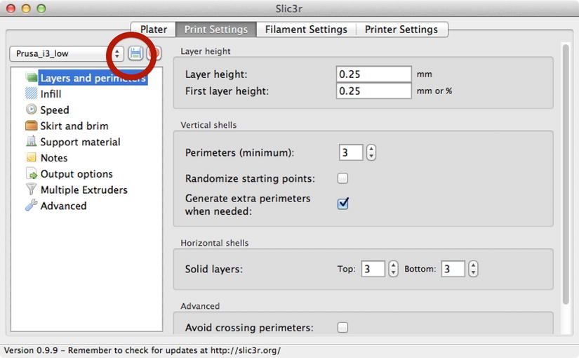
Figure 6-26. Saving the Print Settings profile

Figure 6-27. Saving the Filament Settings profile
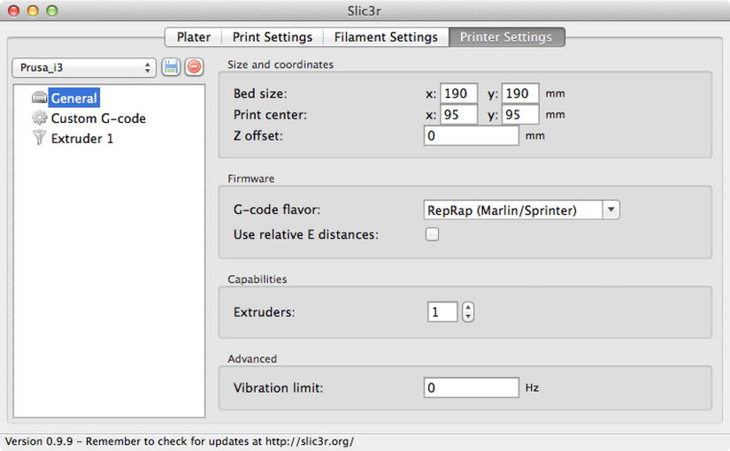
Figure 6-28. Saving the Printer Settings profile
Notice that I named the profiles Prusa_i3_Low for the print settings, RED_ABS_210 for the filament settings, and Prusa_i3 for the printer settings. You can save the profile by clicking the disk symbol below the Plater tab. Naming not only saves your settings, but also allows you to reuse them later. For example, if you create filament profiles for several filaments, you can simply choose the one that matches your filament rather than reentering all of the data each time you print.
![]() Note The Plater tab will not be visible if Slic3r was launched from Repetier-Host by clicking the Configure button on the slicer page.
Note The Plater tab will not be visible if Slic3r was launched from Repetier-Host by clicking the Configure button on the slicer page.
Recall there are a great number of settings for each of these panels. For example, the print settings dialog controls the print quality, and you can set the layer height, infill, and other quality settings here. For now, you can leave them as the default.
To demonstrate how you would choose these profiles in your printer controller software, Figure 6-29 shows an excerpt from the slicer page of Repetier-Host. Notice that I chose the profiles that I saved in the previous steps.

Figure 6-29. Choosing Slic3r profiles in Repetier-Host
Now that you have your slicer application configured and the profiles saved, let us discuss some considerations for printing your first object.
Printing Your First Object
Now that you have your print surface prepared, your Z-height set correctly, and your slicing options set, you’re ready to print! This section will present an overview of how to print objects with your 3D printer.
While it is possible that you can start printing whatever you want at this stage, you should consider one more calibration step—printing objects to test your calibration settings. I know that seems like a waste of good plastic, but I hope the following sections will reveal how important it is to do this step. Indeed, it will help temper your expectations concerning the print quality capabilities of your printer.
I’ll present a brief overview of the printing process, and then discuss printing calibration tests in more detail.
![]() Note If your printer is of sufficient quality, you may not need to print calibration objects. For example, the MakerBot printers come fully configured and ready to print after a few short setup tasks (including tramming the print bed).
Note If your printer is of sufficient quality, you may not need to print calibration objects. For example, the MakerBot printers come fully configured and ready to print after a few short setup tasks (including tramming the print bed).
Printing Process
The process to print is as follows. Note that it can vary from one printer to another, because some may not have heated print beds, or may require different software (e.g., MakerBot and MakerWare), or want to print without a computer (via an SD card). However, the following is general enough to represent most printers. I explain the steps in more detail in the next sections.
- Power on the printer.
- Check and set the Z-height.
- Load the filament.
- Launch your printer controller software.
- Home all axes.
- Choose your slicer settings.
- Turn on the heaters (extruder, print bed).
- Load and slice the object.
- When your heat goals are reached, print the object.
![]() Tip You can complete some of these steps in parallel. As you become more comfortable with the process, you could perform the slicing of your object, including changing profiles while you wait for the heaters to warm up.
Tip You can complete some of these steps in parallel. As you become more comfortable with the process, you could perform the slicing of your object, including changing profiles while you wait for the heaters to warm up.
First, you need to load filament in the extruder. If your printer does not have a spool holder, make sure you have unwound a length of filament and that it is laying in such a way that it can be pulled by the extruder without snagging. If you want, you can cut off about two to three loops of filament from the spool and drape it across the back of the printer. The important thing is that the filament should have little or no friction and that the extruder can pull it easily.
Follow the instructions in your printer documentation to prepare the extruder for printing. This will require heating the extruder and advancing the filament until it, well, extrudes. I like to extrude about 30mm to ensure that the filament moves freely through the extruder and hot end.
![]() Tip A must-have accessory is a spool holder. If your printer doesn’t have one, check Thingiverse for the many variants of spool holders. Most are ones you print and assemble, but some are clever uses of common materials like small-diameter PVC pipe and fittings. Choose one that introduces as little friction as possible. You can also use a lazy Susan with the spool on its side.
Tip A must-have accessory is a spool holder. If your printer doesn’t have one, check Thingiverse for the many variants of spool holders. Most are ones you print and assemble, but some are clever uses of common materials like small-diameter PVC pipe and fittings. Choose one that introduces as little friction as possible. You can also use a lazy Susan with the spool on its side.
Next, power on the printer (if you haven’t already), check the Z-height, and then home all axes.13 Then, start Repetier-Host on your computer. Once Repetier-Host is running, connect to your printer and turn on the hot end in the print panel. You may need to enter the temperature setting in the extruder section of the Repetier-Host print panel. Be sure to use the value you specified in the slicer.
While the extruder is heating, go back to the object placement page and click the Add STL File button. Locate your cube (the .stl file), and choose it. You should see the cube in the center of the platform.
Next, click the Slicer page and choose the profiles you created previously. Once set, click the Slice with Slic3r button. Once this is complete, you will see the G-code listing.
You are all set to start printing once the extruder heats up. Click the Temperature Curve button to watch a graph of the extruder.
Once the heat goal is met, click the Run button on the toolbar. Your printer will start printing the object within a few moments. Depending on the speed of your printer (and the speed settings you set in your slicer), it may take 15 to 20 minutes to print the cube. Allow it to cool for about 5 to 10 minutes before removing it from the print surface.
Calibration Prints
A calibration print is a special object designed to test how well your printer performs on certain tasks. For example, you can print a cube to test the accuracy of your axes movement, print an object with several round holes to check precision, print an object with overhangs to test how well your extruder performs, print a hollow object to check bridging, and much more.
I recommend starting with the cube. It is the best way to see how well you’ve done in setting up your printer. This can be very rewarding for those who have built their own printers. The cube will allow you to measure how well your axes are moving. That is, if you print a 20mm cube, you would expect to measure the resulting object and see that it is 20mm on each side.
Well, that’s the goal. In reality, most printers will be slightly off, but only by a tenth of a millimeter or so. Any more than that and you will have to go back and perform axis calibration. The objects may be slightly off for several reasons. Most notably may be because the filament may have slightly different cooling properties or there may be small imperfections in the layers. Whatever the cause, it is generally acceptable for objects to be a few tenths of a millimeter or so off.
You can find calibration cubes on Thingiverse or you can create your own using OpenSCAD. I will discuss OpenSCAD in more detail in a later chapter; however, creating a simple cube requires only the basics of how to use OpenSCAD. Let’s do that now. If you have not installed OpenSCAD, do so now.
Begin by opening OpenSCAD. Notice that it launches with a new window. Type the following in the edit box on the left side of the screen.
cube([20,20,20]);
This will generate a cube 20mm on each side. The order of the sides are X, Y, and Z. For example, if you wanted a cube that was 10mm wide (X), 20mm deep (Y), and 5mm tall (Z), you would use this command.
cube([10,20,5]);
Now we need to compile it. You can choose the Design ![]() Compile and Render menu item to compile the code and generate a rendering of the object. You should see the cube appear to the right. That’s it! You’ve just written code to generate a 20mm cube. Cool, eh?
Compile and Render menu item to compile the code and generate a rendering of the object. You should see the cube appear to the right. That’s it! You’ve just written code to generate a 20mm cube. Cool, eh?
Now we need to generate a .stl file for use in the slicer. Choose the File ![]() Export
Export ![]() Export as STL... menu14 and give the file a name—like cube_20 or similar. If you want to save the OpenSCAD file, you can do so, but given how simple the code is, you may want to skip saving it. You can always type the code again if you want to make a different cube. OK, we’re all set! I will show you how to slice the cube in the next section. But first, I want to present some test cases.
Export as STL... menu14 and give the file a name—like cube_20 or similar. If you want to save the OpenSCAD file, you can do so, but given how simple the code is, you may want to skip saving it. You can always type the code again if you want to make a different cube. OK, we’re all set! I will show you how to slice the cube in the next section. But first, I want to present some test cases.
In each test case, I discuss the implications of the results of measuring the cubes. I begin with a look at a 20×20×10mm cube printed on a new MakerBot Replicator 2. Figure 6-30 shows the first test case as a collage of the measurements in the order of X, Y, and Z axes.

Figure 6-30. MakerBot Replicator test cube
Notice here that the size of the cube is very close to what was expected. Specifically, the X axis measured only 0.1mm larger than 20mm. The Y and Z axes measure even closer to the desired size. In my opinion, there is no need to further calibrate this printer because it generates objects that are sized with a low tolerance.
HOW CLOSE IS CLOSE ENOUGH?
Depending on how you will use your printer, the objects you print may not need to be exact. For example, if your objects are used as parts to build another printer, so long as the object prints correctly and tolerances allow for slightly larger outer dimensions, you may not need to adjust your printer calibration settings. So how close is close enough? I think it depends on the printer. For instance, a factor of 0.2mm–0.4mm is acceptable for most entry-level and RepRap printers. For consumer- and professional-grade printers, 0.0mm–0.2mm is acceptable.
The next test case shows a 15×15×15mm cube printed on a Printrbot Simple. Figure 6-31 shows the results. Here we see the measurements are a bit more than expected. For the X and Y axes, the object printed 0.36mm and 0.38mm larger, whereas the Z axis printed only 0.19mm larger.

Figure 6-31. Printrbot Simple test cube
While this may sound like a very large error factor, if you consider the printer hardware, it really isn’t that bad. Overall, the test case result on the Printrbot Simple is reasonable for an entry-level printer. Specifically, the Printrbot Simple uses a friction wheel and fishing line to move the X and Y axes. As a consequence, the mechanism is not as accurate as the MakerBot Replicator. However, if you factor in the cost difference, the slightly large result is still impressive. Conversely, the Z axis uses a threaded rod, which permits a better accuracy. Here we see the accuracy is within 0.20mm (2 tenths of a millimeter, or 200 microns).
The next test case was printed on a poorly calibrated RepRap Prusa i2. It illustrates one of the problems early RepRap builders faced when relying on inaccurate calculations. Figure 6-32 shows a 20×20×20mm test cube.
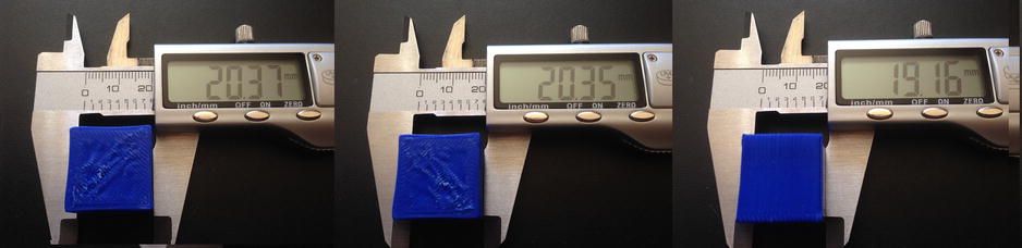
Figure 6-32. Uncalibrated RepRap test cube
At first glance, the X and Y axes appear to be slightly larger, but otherwise are not too bad. However, there is one element to this test case that is unique. If you look closely, you may notice the cube sides are concave. You can see this by looking at the left arm of the X- and Y- inset photos. Notice the slight curve. Figure 6-33 shows the measurement of the cube along the center of the sides.
One thing that tipped me off to something being wrong is the measurement of the Z axis. Here we see that the measurement is significantly less than 20mm. In this case, the error factor is too significant and requires recalibration.
Notice that the figure shows a measurement perpendicular to the axis to be only 0.13mm larger. A closer examination of the cube shows that the edges of the X and Y axes bulge. This is caused by too much filament extrusion. If you look at Figure 6-33 again, you can see the irregular layers.

Figure 6-33. Measuring the axis perpendicular to the axis
So in this test case we have two problems. First, the Z axis is not calibrated correctly and the filament settings need to be checked. When I acquired this printer and discovered these anomalies, I recalibrated the Z axis by checking the calculations against the firmware. I found a minor difference (error) that, once corrected, produced much more accurate Z-axis measurements.
For the filament issues, I changed the settings in the slicer to match the filament in the printer, and the concave problem improved dramatically. I kept this cube to demonstrate how calibration issues can sometimes be related to other settings—in this case, filament settings. Furthermore, this test cube shows a worst-case scenario that should not happen for you if your calculations and firmware settings are accurate.
![]() Note It is possible the error could have been caused by the Z error alone. That is, the layers could be more compressed and therefore bulge more than expected.
Note It is possible the error could have been caused by the Z error alone. That is, the layers could be more compressed and therefore bulge more than expected.
Now let’s redeem the trusty RepRap variants with an example from a properly calibrated Prusa i2. Figure 6-34 shows a 15×15×15mm cube printed in ABS plastic. Notice that the measurements are much closer to what you would expect for a properly calibrated printer.

Figure 6-34. Calibrated RepRap test case
If you print several calibration test cubes and find your measurements are off by more than 0.2mm–0.4mm, you may want to consider recalibrating your printer. You should also observe the print carefully for sides that are not flat or have similar aspects that can cause your measurements to be inaccurate. If you find these characteristics and your measurements are within about 0.2mm, you should not recalibrate until you explore solutions for those problems. For example, if the first layers appear to be squished, it can cause your Z-axis measurement to be less than what you expect. In this case, it indicates the Z-height is too small, causing the first layer to smash into the print bed.
But before you do that, print a second (or even a third) cube to ensure that you are seeing consistent results. If so, try printing a larger cube. If the error factor remains constant from a small to a larger cube, I would not recalibrate because the inaccuracy may be related to other, less significant factors. However, if the inaccuracy scales with the cube, it is definitely a calibration issue. If you do decide to adjust your printer settings, be sure to adjust one axis at a time, reprint the cube, and check the measurements.
Finding Things to Print
OK, so you’ve got your printer dialed in and calibrated. Now what? Well, find something to print! In Chapter 1, I briefly discussed Thingiverse, a repository for 3D objects and designs. It is an excellent source for finding objects that someone else has designed and shared with the world. The objects range from rather simple and easy to print, to very complex and challenging to print. You should look at the easier-to-print objects for your first real object. This is especially true if you are new to 3D printing. After all, you want to show off your new hobby to your friends, right? So what should you try to print?
Getting Started
There are some popular objects that you may want to consider printing first. Start with objects that are small, have no overhangs or bridges, and no small diameter protrusions. All of these features can be harder to print and prone to a number of printing problems. In other words, don’t expect to be a master 3D printer right out of the gate. You need to spend time learning how your printer responds to different filaments, heat settings, and so forth. Only time and experience will give you these answers.
The following lists a few objects that I recommend you try as your first print. Some of these are quite impressive despite their simplicity. Figure 6-35 shows an example of each object.

Figure 6-35. Example first prints
- Stretch bracelet ( thingiverse.com/thing:13505): A nice, wearable 3D object. Good for a first, real print job. Prints quickly in about 20 to 30 minutes.
- SD card holder (thingiverse.com/thing:9218): A practical tool for organizing SD cards. This will take a little longer to print due to its size. Expect print time to be about 1 to 2 hours, depending on your print settings.
- Whistle (thingiverse.com/thing:1046): A bit more of a challenge, but well worth the effort and time to print. Creates a real whistle that you can give away to friends. Make a bunch of them! Print time is under an hour. See the thing information page for details on how to make the pea work (it’s printed inside the whistle).
If you print an object and encounter problems, don’t worry. I cover how to troubleshoot common printing problems in later chapters. For now, you should check you Z-height, slicer settings, and print surface to make sure all is well there.
That being said, some printers, such as the MakerBot Replicator 2, will likely give you good prints right out of the box. If you built your own printer from a kit or from scratch, and followed the advice in the book, you should get a decent print. Don’t feel bad if it takes you more than two attempts to get one of the objects to print correctly—it is part of the learning curve associated with 3D printing.
Searching
Once you’ve printed these objects successfully, it is time to start looking for something else to print. With so many things available on Thingiverse, you could easily spend hundreds of hours printing your favorite things. Fortunately, MakerBot added a feature to Thingiverse called “like”. It is available to anyone who signs up for an account. You use it to mark things you like so that you can quickly revisit them in the future. I like to browse through the things, and when I see something I like, I mark it by clicking “like”. You can then navigate to your “Things I Like” page and quickly find those objects you want to print.
You can simply browse through the objects on Thingiverse or you can also search for keywords like duck, bunny, shower curtain, and so forth, to find things. There is a search text box at the top of the web page. Type in what you want to search and press Enter.
For example, if you want to make some new shower curtain rings, search for “shower curtain”. You should see several examples. Mark the ones you like, and then go back to your account and look through them. Figure 6-36 shows an excerpt of the results for a search of shower curtain.

Figure 6-36. Thingiverse search page
Notice the Sort setting in the upper-right corner. The default sort is Relevant, which shows the results that most closely match your search terms. Here I have sorted by Most Makes, which ranks the results (in descending order) by the number of people who have made the object. Use this setting to show the items that are most popular. It is usually the case that these objects are generally the better examples. That is, the more people that have made them, the more likely these objects are the better examples—either for accuracy or applicability. You can also sort by Newest to show those objects that were uploaded to Thingiverse most recently. You can use this setting to see the most up-to-date versions of those objects that have been modified.
Once you have found an object you like, just click it in the search results. This will show the details for the object. Figure 6-37 shows one of the shower curtain rings from the example search.

Figure 6-37. Example object (created by schmarty)
To download the thing, click the Download This Thing button, which will open the Thing Files panel. Once there, click the Download All Files button and save the .zip file some place on your system. From there, you can extract the .zip file, and then import the .stl file into your slicer or into Repetier-Host for slicing and printing. Figure 6-38 shows the same object loaded in Repetier-Host and ready for printing.

Figure 6-38. Object sliced in Repetier-Host
The details page on Thingiverse has several tabs that you can click to get more information. Not all objects have all of the tabs enabled. For example, if the creator did not provide any instructions on how to use the object, the instructions tab will be grayed-out. The available tabs are as follows.
- Thing Info: General information about the object. Look here for a description of what the object was designed to do.
- Instructions: More details about how to print, assemble, or use the object. Creators of objects typically include recommendations on infill, number of shells, and so forth, related to quality.
- Thing Files: The location of all files associated with the object. You will find the .stl files here and sometimes the source files. It can be good to have the source files if you want to modify the object to fit your needs. Note that sometimes the source files are specific to certain graphics software. For example, if the object was created with OpenSCAD, you will see a file with an .scad extension.
- Comments: This lists all of the comments other users have made about the object. Registered users can use this as a forum to ask the creator questions or to offer suggestions for improvement, or even better, to encourage the creator with your praise of his work.
- Made: This lists the entries created by users who have made the object and uploaded their results to Thingiverse. Use this list to see examples of how others have printed the object. Sometimes it is good to see what the object would look like in other colors. If you make the object yourself, you can log in to Thingiverse and click the I Made One link in the upper-left portion of the details page, and then upload a photo and a brief description of your results.
- Collections: This lists the collections other users have created to store your object.
- Remixes: This list is updated any time someone creates a new iteration of an existing object. You can use this list to see if there are any variations of the object that you may like better. Remixes usually improve the objects in some unique way. For example, you may find a remix that adds more rigidity or additional features. Remixes are sometimes called derivatives.
OK, so now it’s your turn. Visit Thingiverse and look for something to print, download it, and then upload an image of your results. Doing this makes you a member of the rapidly expanding world of 3D printing.
Once you have used Thingiverse for a while, and especially once you have an account, you will find it a very useful site. Indeed, I find I check Thingiverse before I design my own objects to make sure there isn’t already an object similar that I can use or if there is an object that I can modify in some way to avoid having to design from scratch. In a later chapter, I will show some examples of reusing things.
Summary
If you built your own 3D printer from scratch or from a kit, and have been following along in this chapter to calibrate your printer, you’ve learned some valuable information for ensuring that your printer is properly prepared for printing. If you have a manufactured printer, you may not have done the calibration prints (but you should to ensure that there are no problems). However, the preparation topics in this chapter also apply.
In this chapter, I covered how to complete the calibration of your printer by explaining the types of surface treatments, setting the Z-height, and testing your printer for accuracy. Performing all of these steps may seem like a lot of extra work, but it is worth the effort, as it will ensure that your printer is configured and working correctly. I also covered the steps for printing an object, as well as how to use Thingiverse to find other objects to print.
The next chapter begins a new part of the book that focuses on troubleshooting your printer. I start with focusing on troubleshooting your printer hardware to find the sources of things that can cause print failures or poor print quality.
___________________
1Or new to you.
2It is as close to a magic cure as you’re likely to get for ABS lifting.
3Never, ever attempt to use painter’s tape that is made of plastic of any variety. It will not survive application on a heated print bed and may make a mess of your prints because it may stick to your objects.
4This is one of those YMMV situations. It is harder to control lifting and adhesion problems, and for that reason alone I’d recommend waiting to use blue painter’s tape with ABS until you’ve had some experience controlling lifting and similar adhesion problems.
5Every Apple device I’ve seen has several pieces inside.
6It can also cause larger objects to develop cracks where layers separate during cooling.
7Not to be confused with ABS slurry, which is a thicker concoction used to glue parts together.
8Can you tell what I printed? Hint: it is for a MakerBot Replicator 2.
9Animal hair does not dissolve in acetone.
10It will also dry your skin almost instantly. Guess how I know this? Don’t go there!
11OK, so maybe ABS juice on top of Kapton is unorthodox to some, but it does work well for me.
12Diskette? What’s a diskette? Wonderfully antiquated, isn’t it?
13I cannot understate how important these steps are to print quality. Always check your Z-height and home all the axes before doing any other operations on your printer.
14Older versions had the feature under the Design ![]() Export as STL... menu.
Export as STL... menu.