
![]()
Introduction to 3D Printing
Three-dimensional (3D) printing has evolved dramatically in the last few years. 3D printers have become plentiful and affordable enough that anyone can own one.1 Indeed, the cost of 3D printers (as little as $200 USD) makes them an attractive choice for small businesses, researchers, educators, and hobbyists alike. You can use a 3D printer in your business to create prototypes for manufacturing, develop architectural or engineering models, print miniature terrain and figures for gaming, or fix things around the house.
You can experience a lot of pleasure designing things and holding the results in your hand. Even after several years of printing three-dimensional parts, I often find myself watching the printer build the object layer by layer. It’s still fascinating to me. I enjoy creating solutions for use in my home or office—especially if it saves me money. I also enjoy designing and printing upgrades and improvements for my printers.2 But this enjoyment comes at a price. Some of my printers require attention every time I print, whereas others can operate with little effort.
What this means is, while 3D printers and software have become much easier to use, they are neither toys nor maintenance-free. 3D printers must be properly assembled (if you purchased a kit), adjusted, maintained, and repaired when they break. Many of the problems you will encounter when printing are directly related to some mechanical adjustment or software setting. Unless you have been working with 3D printers for some time or have spent countless hours trolling for solutions while trying to discern hokum from fact, it is easy to become frustrated with your printer when things don’t work out. When you get to this point, you’re well beyond the operators’ manual.
This book provides a depth of information that far exceeds the meager documentation provided with some printers. You will discover many secrets, arcane facts, and techniques for getting the most out of your printer. In fact, I take you through the entire 3D printing experience—from choosing or building a printer, to maintaining and troubleshooting your prints, to designing your own objects.
In this chapter, I present a brief primer on 3D printing. I will cover 3D printing techniques, how 3D printers work, the software required, and the types of plastic supplies, including a brief overview of their properties and uses. I will conclude the chapter with some ideas on what you can expect from your 3D printer and where to get ideas for creating objects.
Getting Started
Before we jump into the various forms of 3D printers and their technologies, let’s talk a little bit about what defines 3D printing. Whether you have recently acquired or built a 3D printer, or are completely new to 3D printing and about to buy your first 3D printer, I think this section will be helpful to set the stage for the chapters ahead. After all, it is always good to know (or review) the fundamentals and terms before jumping into lingo-infested waters, eh?
![]() Note Henceforth I will use 3D printer and printer interchangeably since I will be talking only about 3D printers.
Note Henceforth I will use 3D printer and printer interchangeably since I will be talking only about 3D printers.
What Is 3D Printing?
The most fundamental concept to understand 3D printing is the process by which objects are built. The process is called additive manufacturing.3 Conversely, the process that computer numeric control (CNC) machines use to form objects (starting with a block of material and cutaway parts to form the object) is called subtractive manufacturing. Both forms of manufacture use a Cartesian plot (X, Y, and Z axes) to position the hardware to execute the build. Thus, the mechanical movements for 3D printing are very similar to the mechanisms used in CNC machines. In both cases, there are three axes of movement controlled by a computer, and capable of very high precision movement.
Additive manufacturing has several forms or types that refer to the material used and the process used to take the material and form the object. However, they all use the same basic steps (called a workflow) to create the object. Let’s start from a raw idea and see how the idea is transformed into a physical object using additive manufacturing. The following lists the steps in the process at a high level.
An object is formed using computer-aided design (CAD) software. The object is exported in a file format that contains the standard tessellation language for defining a 3D object with triangulated surfaces and vertices (called an .stl file).
![]() Note There is a new file format—named additive manufacturing file (AMF) format—that is becoming more popular. It was designed to extend the capabilities of STL and may emerge as the choice in the near future.
Note There is a new file format—named additive manufacturing file (AMF) format—that is becoming more popular. It was designed to extend the capabilities of STL and may emerge as the choice in the near future.
The resulting .stl file is split or sliced into layers, and a machine-level instruction file is created (called a .gcode file) using computer-aided manufacturing (CAM) software. The file contains instructions for controlling the axes, direction of travel, temperature of the hot end, and more. In addition, each layer is constructed as a map of traces (paths for the extruded filament) for filling in the object outline and interior.
![]() Note MakerBot printers use a slightly different file format, .x3g or the older .s3g, instead of .gcode. The use of the file is the same. It contains commands to tell the printer how to print the object.
Note MakerBot printers use a slightly different file format, .x3g or the older .s3g, instead of .gcode. The use of the file is the same. It contains commands to tell the printer how to print the object.
The printer uses its own software (firmware) to read the machine-level file and print the object one layer at a time. This software also supports operations for setting up and tuning the printer.
This last step is where most 3D printing forms differ. That is, they vary slightly in the mechanism used and the materials used to form the object. However, all additive types use the same concept of taking an object and building it in layers. Table 1-1 lists some of the forms available, describes how the material is used to build the object, and tells what materials can be used.
Table 1-1. Types of Additive Manufacturing
Type |
Build Process |
Materials |
|---|---|---|
Filament |
Objects built layer by layer, where material in filament form is extruded from a heated nozzle. |
Various plastics, wood, nylon, and so forth. |
Wire |
An electron beam is used to melt the wire as it is unspooled to form an object layer by layer. |
Most metal alloys. |
Granular |
Various processes are used to take material in a raw, granular form using a laser, light, or electricity to fuse the granules and build the object. |
Some metal alloys and thermoplastics. |
Powder |
A reactive liquid is sprayed on a power base to form solid layers. Some variations use a multistep process to fuse and then bind materials. |
Plaster and similar cranular materials. Emerging solutions can use metal. |
Laminate |
Material is laid over the object and fused with a heated roller. A laser is then used to cut out the shape. |
Paper, metal foil, plastic film. |
The most common form of 3D printing is called fused filament fabrication (FFF). Since the majority of 3D printers available today for consumer purchase4 are FFF, I will only discuss FFF in depth in this book. To simplify our discussion, henceforth I consider 3D printing to be synonymous with the FFF process. In fact, all printers discussed in this book are FFF-based.
WHERE DID FUSED FILAMENT FABRICATION ORIGINATE?
FFF is also known as fused deposition modeling (FDM). FDM was developed by S. Scott Crump in the late 1980s, and further developed and commercialized by Stratasys Ltd. in the 1990s. Indeed, FDM is a trademark of Stratasys Ltd. (the owners of MakerBot Industries). Since the majority of 3D printers use this process (the process is not trademarked, only the term FDM), we use FFF to avoid confusion with the Stratasys trademark.
When a 3D printer creates an object, the material used to print an object comes in filament form5 on a large spool to make it easier for the printer to draw material. The filament is then loaded into an extruder that has two parts: one to pull the filament off the spool and push it into a heating element, and another to heat the filament to its melting point.
The part that pulls the filament and feeds it to the heating element is called the cold end, whereas the heating element is called the hot end. In most cases, the extruder contains both parts in a single unit, but it is not uncommon to see these as two separate parts. Sometimes manufacturers refer to both parts as the extruder, but others distinguish the extruder from the hot end (but they sometimes don’t call it a cold end). Just one of the many nuances to 3D printing I hope to explain!
![]() Tip Never buy filament that isn’t on a spool or a similar orderly delivery mechanism. Improperly wound filament can introduce a maddening number of extrusion failures. We will see why in a later chapter.
Tip Never buy filament that isn’t on a spool or a similar orderly delivery mechanism. Improperly wound filament can introduce a maddening number of extrusion failures. We will see why in a later chapter.
If this sounds like nothing more than a fancy hot glue gun, you’re right! The process is very similar, but unlike the hot glue gun that relies on human power to pump glue sticks (however inaccurately) into the heating element, 3D printers use a computer-controlled electric motor called a stepper motor to precisely control how much and how fast the filament is fed to the hot end. Most extruders use a geared arrangement to allow the stepper motor to apply more torque to the filament to overcome forces such as the tension of the spool or the weight (and thickness) of the filament.
Figure 1-1 shows a drawing of how the extrusion process works, including a pictorial representation of the components discussed in this section.

Figure 1-1. FFF extrusion with nomenclature
The drawing shows a mock-up of the extruder and a spool of filament. As you can see, the filament is pulled into the extruder (cold end) and then pushed into the nozzle (hot end). Once heated, the filament is extruded onto a build plate (a very flat surface used as the base for the object). Typically, the outer edges of an object are printed first, then the interior edges are printed, and finally, the interior of the layer is printed as either a solid layer (for outer-most layers) or as a fill-in matrix for inner layers.
Notice that the filament from the spool is much larger than the heated extrusion. This is because most nozzles (the small part where the filament exits the heater block) have a very small opening ranging from 0.3 millimeters (mm) to 0.5mm. Notice in the drawing I’ve exaggerated how the layer is built from multiple lines of heated filament. While grossly simplified, this is effectively how a 3D printer takes filament and builds a layer of the object.
Figure 1-2 shows an example of a printed part that was stopped after only a few layers. On the left is the bottom of the part. The part on the right shows what the default fill pattern and density look like. Notice that the edges are made from several passes of the extruder, but the interior is only partially filled. This not only saves filament but also ensures the part will have sufficient strength.

Figure 1-2. Example print
Now that we understand how a 3D printer puts the filament together to form an object, let’s take a look at the software required for 3D printing. I will introduce the types of software needed and briefly discuss how they are used, and also provide a short demonstration of how to use the software to print an object. If you want to install the software, refer to the URLs listed for installation instructions.
There are three pieces of software involved in 3D printing: software required to create the object and export it as an .stl file (CAD), another to convert it into a G-code file that a printer can read (CAM), and finally, the firmware loaded in the “brain” of the printer itself that reads and executes the .gcode file. We call the printer software firmware because it is typically loaded once into a special memory device built into the electronics for the printer and started when the printer is turned on. You rarely ever need to change or modify the firmware (other than an initial load and calibration).
But wait, there’s one more piece. Often overlooked, there is a fourth category of software often used in 3D printing and it may be the most important of all to your satisfaction! It’s the printer control application. This software allows you to connect your computer to your printer (via a USB connection) and perform many operations, such as moving the axes, turning the hot end on/off, and aligning the axes (called homing).
I routinely use a 3D printer controller as part of my normal setup routine. Some printers come with an onboard LCD control panel that has controls for moving an axis and setting the temperature. Most support an SD card for reading G-code files. If your printer is already adjusted and ready to go, you can use this feature to print objects without tying up your computer for the duration of the print.
![]() Caution If you print from your computer, don’t disconnect your computer until the job is done! Can you guess what happens if you do? You’ll end up with a partially complete part to add to your growing pile of printing horror stories.6
Caution If you print from your computer, don’t disconnect your computer until the job is done! Can you guess what happens if you do? You’ll end up with a partially complete part to add to your growing pile of printing horror stories.6
Many 3D printing experts and manufacturers refer to the software as a “tool chain” because of the way you must use one piece of the software at a time to realize an object. Some manufacturers, like MakerBot Industries (www.makerbot.com), provide their own software that combines an object visualizer and slicer (CAM), as well as a printer controller. MakerBot calls its software suite MakerWare (www.makerbot.com/makerware/). Ultimaker calls its software suite Cura (http://wiki.ultimaker.com/Cura). Other examples of combined tools are the Repetier suite (www.repetier.com) and Printrun (http://reprap.org/wiki/Printrun). Each of these is an interface to the CAM software (the slicer) and each provides a printer controller feature.
![]() Note When I discuss aspects of a type of software in general, I use the term software. When I speak of an implementation of the software, I use the terms program and application.
Note When I discuss aspects of a type of software in general, I use the term software. When I speak of an implementation of the software, I use the terms program and application.
If you are about to purchase or have already purchased a printer that does not come with software, do not despair! Much of the 3D printing world has adopted the open source philosophy, and as a result there are several options to choose for each software category. I will discuss each of these and show some examples of MakerWare and other solutions in the following sections. I will also explain the types of files you will generate from each step.
WHAT IS OPEN SOURCE?
Open source means the software or hardware is free for anyone to use. Think free as in “free speech,” not free as in free beer. Most open source products have a license associated with it, designed to define ownership and outline the permissions that users have. For example, if something is marked as open source, it may be that the license allows you to freely use and even distribute. The license may also permit you to modify the product, but require you to surrender all modifications to the original owner. So while you can use it for free, it isn’t yours to own. Always check the license carefully before using, distributing, or modifying the product.
Computer-Aided Design
Simply put, computer-aided design (CAD) is software that permits you to use a computer to create an object. CAD software typically includes features to realize an object in various 3D views, manipulate the object surface and interior details, as well as change the view of the object (scaling, rotating, etc.).
![]() Note CAD is also referred to as computer-aided drafting, but in this case it refers to the drawing aspect alone. I spent several years learning the art of mechanical drawing.7 Computer-aided drafting revolutionized that aspect of the engineering discipline. In fact, learning computer-aided drafting software is what got me interested in the engineering disciplines.
Note CAD is also referred to as computer-aided drafting, but in this case it refers to the drawing aspect alone. I spent several years learning the art of mechanical drawing.7 Computer-aided drafting revolutionized that aspect of the engineering discipline. In fact, learning computer-aided drafting software is what got me interested in the engineering disciplines.
Advanced CAD software has features that allow you to create a number of objects and fit them together to form a complex mechanical solution (called a model). Advanced CAD software includes additional features that test fit, endurance, and even stress under load. An ultimate example would be the software that automotive manufacturers use to construct engines. I have seen examples of such software that can animate all of the moving parts and even suggest ways to improve the individual components.
There are many CAD applications available with a wide range of features. To be used with 3D printing, they must, at a minimum, permit you to design shapes in three dimensions, define interior features like holes for mounting the object, and basic tools to add a surface or facing to the object.
The various CAD applications save the models in a specific, sometimes proprietary, format. This limits the possibility of using several different CAD applications to manipulate an object. Fortunately, most permit you to import models and objects from various file formats.
More importantly, the software must permit you to create an object that is manifold (has an inside and outside surface with no gaps). This is important because the slicer needs to be able to create paths for the filament to follow, and gaps or holes means there is a break in the path. Attempting to force the slicing and printing of a nonmanifold object will result in an undesirable end result. I tried it once with a whistle and ended up with a solid block in the shape of a whistle—it filled the interior with solid plastic. Tragic.
![]() Tip If your slicer program displays an error that your object is not manifold, you can use an online tool from NetFabb to fix the holes. Visit http://cloud.netfabb.com, select your object, enter your e-mail address, agree to the terms and conditions, and click “Upload to cloud”. After a few moments, you will get an e-mail with a link to the fixed object. I have fixed a number of objects like this. While you are there, check out the cool online 3D printing tools they offer.
Tip If your slicer program displays an error that your object is not manifold, you can use an online tool from NetFabb to fix the holes. Visit http://cloud.netfabb.com, select your object, enter your e-mail address, agree to the terms and conditions, and click “Upload to cloud”. After a few moments, you will get an e-mail with a link to the fixed object. I have fixed a number of objects like this. While you are there, check out the cool online 3D printing tools they offer.
Remember, CAD applications for 3D printing must be capable of creating a standard tessellation language (.stl) file so that the CAM software can read the file, slice it, and create a printer instructions (.gcode) file for forming the object in three dimensions.
CAD Software Choices
There are a lot of applications that provide CAD features that you can use to create 3D objects. You can find some that are open source, some free to use (but limited in some way), and those that you must purchase. Most have a graphical user interface that allows you to see the object as you build it. As you will see, there is one that uses a C-like programming language to build a script to create the object. Some applications are available for online use. Furthermore, some are easy to use, whereas others take a lot of time to learn. In general, the more features the software application has, the more difficult it is to use.
If you are just starting out, you may want to try an application with fewer features until you get the hang of it or outgrow its features. Table 1-2 contains a list of some of the more popular CAD solutions, including cost basis, degree of difficulty to learn (how long it takes to create your initial object), and type of interface. This is not an exhaustive list, but it is a list of the choices known to export or save files in .stl format. In the next sections, I highlight the first (most difficult/full-featured) and last (easiest) options available.
Table 1-2. CAD Software for 3D Printing

The Blender CAD application (blender.org) is a veritable Swiss army knife of CAD software. Not only can you create highly detailed 3D models, you can also create 3D animation and more! For 3D printing, it’s really overkill for most of the types of objects you will create. On the other hand, if you plan to develop complex models for commercial use or for creating parts for a complex solution, you will want to take a hard look at this application. Figure 1-3 shows a screenshot of the Blender application.

Figure 1-3. Blender CAD software
The example shows the editor window in which an object has been loaded. In this case, it is the extruder body for the Greg’s Wade hinged extruder. I was able to import the .stl file, and Blender converts it so that I can modify the object however I like. For example, I may want to move the mounting holes or cover the existing legacy mounting holes (the ones for mounting on a Prusa Iteration 2 X-carriage).
If I had modified the object, I could save the object (model) and export it to a different .stl file, slice it, and print it. Clearly, this could be a useful feature if you need to modify an object but do not have the CAD software with which it was created. Perhaps best of all, it is open source!
I rated this application with a high level of difficulty for several reasons. First, there are a dizzying number of features to learn and hundreds of menu choices. It is definitely not something you can sit down and learn in an afternoon. However, it is a first-rate CAD solution—one that you would do well to master if you plan to design highly complex objects.
The good news is that there are a number of books available to learn Blender. If you want to master Blender, I recommend spending some time with the included documentation and seek out one or more of the following books:
- Lance Flavell, Beginning Blender: Open Source 3D Modeling, Animation, and Game Design (Apress, 2010)
- Roland Hess, Blender Foundations: The Essential Guide to Learning Blender 2.6 (Focal Press, 2010)
- Gordon Fisher, Blender 3D Printing Essentials (Packt Publishing, 2013)
This solution is on the opposite side of the difficulty scale. Indeed, if you know a little programming (or at least the concepts of writing executable scripts), you can create simple objects very quickly without reading tome after tome of instruction manuals.
To build an object, you begin by defining a base object (say a square) and add or subtract other shapes. For example, to build a standoff for mounting a printed circuit board (like an Arduino or a Raspberry Pi), you start with a cylinder (the outer perimeter) and “subtract” a smaller cylinder (the inner perimeter). While this sounds simple, you can use this very simple technique to create very complex objects.
In fact, this is the process that was used to create the plastic parts for a popular variant of an open source printer created by Josef Prusa. Figure 1-4 shows an example of one of the models that Josef Prusa created.

Figure 1-4. OpenSCAD example (GPL v3)
Take a moment to observe the figure. Notice that there are three parts to the interface. On the left is the code editor window where you enter all of the statements for defining your objects. On the right, at the top, is a view of the model (generated when the script is compiled) and below that is a list of feedback and messages from the OpenSCAD subprocesses and compiler.
As you can see, you can create very complex objects and even several in the same file. When you save the file, you are actually only saving the statements and not a rendered model. This enables you to save a lot of disk space (CAD-based files can be quite large), but you must compile the script to visualize the object(s).
OpenSCAD allows you to export the compiled model in a variety of formats that can be opened by other CAD applications for further manipulation. More importantly, you can generate the required .stl file for use in a CAM (slicer) application, permitting you to use OpenSCAD as the first stop in your 3D printing tool chain.
Even if you do not know the language, it is not difficult to learn and there are many examples on the web site (www.openscad.org) to help you get going. If you are looking for something to get started quickly, you will want to consider using OpenSCAD until you need the more advanced features of the larger CAD applications.
Thingiverse: An Object Repository
If you are thinking that learning a CAD program is a lot of work, you’re right, it can be. Learning Blender can be a steep curve but if you favor a GUI with advanced features, the learning curve comes with the territory. The other GUI-based CAD programs have varying demands for learning to use, but most require you to learn a specific set of menus and tools. On the other hand, OpenSCAD is easier to use if you think in code, and therefore you may not need to use a complex GUI and all of its trappings to design your own objects.
But what if you don’t have the time or the inclination to design your own object? Wouldn’t it be great if there were a place where you could download .stl files of interesting and useful objects for printing? That’s exactly what the nice people at MakerBot were thinking when they created a site called Thingiverse (thingiverse.com).
Thingiverse is a place where anyone can upload and post information about their objects (ones they have created or modified by permission) for anyone to view and use. Most of the objects on Thingiverse are open source, so you need not worry about intellectual property violations—but always read the license! Figure 1-5 shows a snapshot of the Thingiverse web site.

Figure 1-5. Thingiverse
The site is free for anyone to browse, search, and download objects. You don’t even need to create an account! Once you find an object you want to use (print), simply click the Download button and save the files to your hard drive. Most files are in the .stl format, so you need only slice it and print it.
Registered users can create objects, mark objects for printing later, tag things that they like, organize things into collections to keep a virtual file of these things, and keep tabs on any objects uploaded. You can also share with others the objects you have printed (made). It is always nice to find a thing you like and see examples of it printed by others.
![]() Tip The best objects are those that a lot of people like. Watch for things that have been made often. This is indicative of a well-designed (and useful) thing.
Tip The best objects are those that a lot of people like. Watch for things that have been made often. This is indicative of a well-designed (and useful) thing.
When you find a part you want to see in more detail, simply click on it. You will then see a detailed page with a list of photos of the thing (a 3D view and one or more photos that the creator has uploaded). The page also includes a menu or tabs (varies among platforms) that include entries for a description of the object (thing info), instructions for assembly (optional), a list of the files available, and a comments section where anyone can comment or ask the creator questions. There are also statistics on the number of people that have liked the object, added it to a collection, or printed (made) it.
If you want to create your own objects and share them with others, you will need to sign up for an account. The account is also free, but you will need to identify yourself (name, etc.) so that you can post objects. I have posted a number of objects. Figure 1-6 shows one of my early designs for mounting a light ring around the hot end of a Prusa Iteration 2 printer.

Figure 1-6. An object on Thingiverse
This is a nifty upgrade that makes watching the print much easier. I use the LED to help me determine early on whether I am getting good adhesion to the build surface. It has helped me stop a number of prints that would have failed (corner lift or loss of adhesion altogether) had I not had more light to catch the problem before too much of the part was printed.
The Thingiverse web site works for most browsers and platforms. There is even a Thingiverse app for your iPhone or Android device so you can see what has been added since your last visit. Simply go to the site, click the Explore menu item, and choose Newest. I find myself checking for new objects at least once a day. I’ve found many useful objects and inspiration for other objects. Thingiverse is a great asset. I recommend searching Thingiverse before you create any object yourself. Chances are you will find something similar that you can download, slice, and print right away!
You can find all manner of objects on the site. Even though the predominant objects are suitable for 3D printing, you can also find files for laser and water-cutting 2D shapes. Thingiverse is also a major site for hundreds of modifications to many open source 3D printer designs. I have found dozens of interesting upgrades, many of which I have adopted with little or no modification. I will show you some of these upgrades in a later chapter. For now, let’s return to the next step in the tool chain—slicing (CAM).
There are many aspects to CAM, but the one process we need is the ability to take a 3D object definition (an .stl file) and convert it into a file that contains instructions for the printer to build the object layer by layer (a .gcode file). More specifically, the slicer uses numerical control code in the standard tessellation language to create canonical machining function calls in the form of G-codes.
G-code is a shorthand notation for a set of machine functions that govern the movement of the various parts of the machine. While 3D printers read G-code files, the codes themselves are not limited to 3D printers. In fact, the codes cover a wider range of machines, including CNC machines. Moreover, the G-code definition has been modified to include new codes specifically for 3D printing.
The codes are formed by a letter that signifies the class of command, a number (index), and one or more parameters separated by spaces (optional). There are codes for positioning the hot end, setting the temperature, moving the axis, checking sensors, and many more. Let’s look at a few examples in Table 1-3, and then see what a .gcode file looks like, as shown in Listing 1-1.
Table 1-3. Common G-Codes

Listing 1-1. Example G-code File
; generated by Slic3r 0.9.9 on 2014-01-05 at 15:53:58
; layer_height = 0.2
; perimeters = 3
; top_solid_layers = 3
; bottom_solid_layers = 3
; fill_density = 0.4
; perimeter_speed = 30
; infill_speed = 60
; travel_speed = 130
; nozzle_diameter = 0.35
; filament_diameter = 3
; extrusion_multiplier = 1
; perimeters extrusion width = 0.52mm
; infill extrusion width = 0.52mm
; solid infill extrusion width = 0.52mm
; top infill extrusion width = 0.52mm
; support material extrusion width = 0.52mm
; first layer extrusion width = 0.70mm

G21 ; set units to millimeters
M107
M104 S200 ; set temperature
G28 ; home all axes
G1 Z5 F5000 ; lift nozzle

M109 S200 ; wait for temperature to be reached
G90 ; use absolute coordinates
G92 E0
M82 ; use absolute distances for extrusion
G1 F1800.000 E-1.00000
G92 E0
G1 Z0.350 F7800.000
G1 X78.730 Y91.880
G1 F1800.000 E1.00000
G1 X79.360 Y91.360 F540.000 E1.02528
G1 X79.820 Y91.060 E1.04227
G1 X80.290 Y90.800 E1.05889
...
G1 X92.051 Y96.742 E6.11230
G1 X92.051 Y96.051 E6.12185
G1 F1800.000 E5.12185
G92 E0
M107
M104 S0 ; turn off temperature
G28 X0  ; home X axis
M84     ; disable motors
; filament used = 164.4mm (1.2cm3)
The G-code file is a text file that contains all of the machine instructions to build the file, including the setup and teardown mechanisms as defined by the slicer. Listing 1-1 shows an excerpt of a .gcode file. Notice that the first lines are preceded with a semicolon. This indicates a comment line and is commonly used to define the parameters for the print operation in plain English. Notice that the comments indicate layer height, solidity of the top and bottom, density, and much more. This makes it easy for you to determine the characteristics of the file without having to translate the G-codes.
![]() Tip If you plan to print with more than one type of filament, you might want to name the sliced file (the .gcode file) with a code or phrase to indicate what filament is used. This is because each filament type requires different temperature settings. It is also likely that filament of the same type will vary in size or have slightly different melting characteristics.8 All of this data is stored in the G-code file. You may also want to consider making folders, like PLA_3.06 or ABS_BLACK, and store all of the .gcode files by filament type, size, or color.
Tip If you plan to print with more than one type of filament, you might want to name the sliced file (the .gcode file) with a code or phrase to indicate what filament is used. This is because each filament type requires different temperature settings. It is also likely that filament of the same type will vary in size or have slightly different melting characteristics.8 All of this data is stored in the G-code file. You may also want to consider making folders, like PLA_3.06 or ABS_BLACK, and store all of the .gcode files by filament type, size, or color.
If you would like to know more about G-code and the various commands available, see http://reprap.org/wiki/G-code for a complete list of codes supported by most 3D printer firmware. We will see several of the more commonly used G-codes in later chapters.
WHAT IS REPRAP?
RepRap stands for replicating rapid prototyping.9 The RepRap movement began as a vision of Dr. Adrian Bowyer at the University of Bath in 2005, with the goal to build a 3D printing platform that can print a clone of itself.
The term is used to categorize a number of open source 3D printer designs. Most popular and ubiquitous with RepRap are the Prusa iterations created by Josef Prusa. The RepRap world is very large, and supported by a number of communities with some very passionate contributors.
To learn more about RepRap, keep reading this book and visit the wiki at http://reprap.org/wiki/RepRap.
Unlike CAD software, there are few choices for CAM software designed specifically for 3D printing. Recall that the primary function is slicing an object and producing the G-code file that 3D printers require. However, the choices available vary in how much you can control the generation of G-code.
Table 1-4 lists some of the most popular choices for CAM software for use in 3D printing. I will discuss the two most popular choices in the following sections.
Table 1-4. CAM Software for 3D Printing (Slicing)

MakerBot has developed an application called MakerWare (makerbot.com/makerware/) that uses a 3D view that depicts the build platform and its maximum build volume. It allows you to position objects anywhere on the build platform (other CAM applications automatically center the object), generate sliced files (X3D or S3D) for use on their printers, and even gives you an option to see a layer-by-layer preview of the object before printing.
The MakerWare application is optimized for use with MakerBot printers. Indeed, MakerBot has done all of the really hard work for you. Simply stated, it just works—no fuss, no fiddling. Unlike other solutions, there are very few settings you can change—they aren’t needed. However, if you need to fine-tune your prints (the G-codes) beyond the available settings or if you want to print on a non-MakerBot printer, you may want to explore other solutions that offer more customizability and control over the G-code generation.
MakerWare allows you to add objects (.stl files) to your build plate, move and rotate them, and even scale them to fit in the build area. You can also rotate the view in any direction, and zoom in or out. Figure 1-7 shows a snapshot of the MakerWare main interface.

Figure 1-7. MakerWare main window
By permitting you to place the objects anywhere on the build platform, you can overcome the problem when the Kapton or blue tape gets damaged—just put the object somewhere else! Once you have your objects arranged on the build platform, you can click the Make button to enter the slicing function. The slicing feature of the software is highly optimized and streamlined. Unlike other software (as we will see), you can change only a few settings. Figure 1-8 shows the slicing dialog.

Figure 1-8. MakerWare slicing control
The dialog permits you to select which printer you have (Replicator, Replicator 1 Dual, Replicator 2, or Replicator 2X), the material (ABS or PLA), and quality. You can also turn on support material and rafting. You can also print to a file or print directly to the printer (requires a USB connection between the computer and the printer).
Support materials are bits of plastic used to bridge large gaps or add support for extreme overhangs. Think of it as scaffolding used to shore up a portion of the object that would otherwise fail. For example, suppose you wanted to print an object that had a large empty interior. Rather than having the printer attempt to bridge (apply filament across a gap, which can lead to drooping or even failure to bridge the gap) the area, you can turn on support to prevent the filament from drooping in the middle. Adding support means you will have to remove the extra bits to get the part cleaned for use (or admiration of your brilliant design). Dual extruder machines can print using a second filament for support material. In this case, the filament can be dissolved rather than having to be removed or cut away.
Rafting, on the other hand, is a special technique used to improve cooling to prevent portions of the object from cooling faster than others. When this happens, the part can lift off of the print bed itself (called lifting or curling). Rafting is several layers of filament laid down on the print bed prior to printing the object. In the case of MakerWare, the rafting peels away from the part very cleanly.
If you want a bit more control over the print, you can click the Advanced button, which reveals finer control settings for quality, temperature of the hot end, and even the speed of extrusion. Figure 1-8 shows what this looks like. You can also save your customized settings and retrieve them later. This permits you to set up profiles for certain filaments (heat properties for colored filament can vary). Lastly, you can choose to see a preview of the print prior to generating the file. Select the “Preview before printing” check box to see the preview.
The build preview dialog allows you to see a graphical representation of the paths the printer will use to extrude filament. Use the slider on the left side of the dialog to show a range of layers starting from the first layer. Figure 1-9 shows an example of the build preview dialog.

Figure 1-9. MakerWare build preview
Notice in the figure that you can also choose to show the tool paths (Show Travel Moves). This highlights the paths that the extruder will take when moving the hot end into position for printing. For complex or multiple objects, this may generate many lines. For simple objects as shown in the example, it reveals little.
Take another look at the example. Notice I’ve set the layer bar to 27. It shows how the printer will manage the infill and layers. Interestingly, it also shows the raft that is built under the object. To finish your export (slicing action), click Export!.
Finally, not only does MakerWare generate the sliced files, you can also use it to control a MakerBot printer. Thus, it combines the CAM and printer control functions. All of these features mean MakerBot printers are supported from the CAM step onward by a very robust, easy to use application. In many ways, MakerBot has made all of the hard decisions for you ensuring you have a successful print any time you want to print an object.
If you do not own a MakerBot printer, or if you want to control the creation of the G-codes, you will want to check out the Slic3r10 (http://slic3r.org). Like the MakerWare application, Slic3r has an area where you can place objects on a virtual build plate, but unlike MakerWare, the view is top-down, two-dimensional, and automatically centered on the build plate. Figure 1-10 shows the main window in expert mode (simple mode hides many of the advanced controls).

Figure 1-10. Slic3r main window
![]() Note The latest releases of Slic3r will include a three-dimensional view option.
Note The latest releases of Slic3r will include a three-dimensional view option.
Slic3r allows you to have complete control over the generation of the G-codes. There are dialogs for controlling the print, such as specifying infill (quality), perimeters, skirt, brim, and also rafting. There are so many settings, in fact, that you could spend a lot of time fine-tuning your slicing. Don’t worry about those for now. We will explore all of these terms in a later chapter that discusses how to fine-tune your print. There is also excellent documentation online for you to explore every nuance of the software (http://manual.slic3r.org).
Like MakerWare, you can also store profiles, but in this case, you store a separate profile for each of the three major categories: print settings, filament settings, and printer settings. The print settings section permits you to set parameters for how the object will print (e.g., infill). The filament settings section permits you to set the temperature of the hot end (and build platform), as well as the size of the filament. The printer settings dialog allows you to control the printer, including adding custom G-codes—like moving the print bed, turning off fans, and so forth—at the beginning or end of the print job.
You can save your settings for each of these three areas individually. Thus, you can set up special filament settings for each roll of filament you own, as well as set up different printer profiles if you have different printers. More likely, you will set up different print settings to correspond with different levels of print quality, speed, and so forth.
Not only is it likely that filament will have different heating properties, it also can vary in size from one manufacturer to another. It is not unusual to find filament that measures 1.8mm (it should be 1.75mm) or even 3.1mm (it should be 3.0mm). You should always measure your filament and set the dialog accordingly.
![]() Caution Check the size of your filament as you consume it. If it varies in size by more than 0.01mm–0.03mm, you may want to reconsider buying filament from the same vendor. Wildly varying size can indicate inferior filament and can lead to extrusion failures, poorly filled (filament too small) prints, or over-filled (filament too big) prints.
Caution Check the size of your filament as you consume it. If it varies in size by more than 0.01mm–0.03mm, you may want to reconsider buying filament from the same vendor. Wildly varying size can indicate inferior filament and can lead to extrusion failures, poorly filled (filament too small) prints, or over-filled (filament too big) prints.
The main settings you will use to control the print are located on the print dialog. This includes the fill density (infill), print speed, and support material. Figure 1-11 shows and example of the print settings dialog. Notice on the left is a long list of topics. When you click each of these, you can see all of the advanced settings for that category.

Figure 1-11. Slic3r print settings window
Figure 1-12 shows an example of the printer settings dialog depicting the entry page for setting custom G-codes at the start and end of the print job. In this example, I tell the printer to home all axes and lift the nozzle (hot end) 5mm at the start. Then at the end, I tell the printer to turn off the heater(s), move the X axis to home, and disable the motors. You can add your own custom commands here too.

Figure 1-12. Slic3r printer settings window
In many ways, Slic3r is more of a professional tool than MakerWare. This is because Slic3r gives you far more control over the generation of the G-code file, and thus the printer itself. All of this power comes with a price, however. You should tread carefully when modifying the many settings, making sure you change only certain areas at a time.
In fact, I recommend testing your ideas using a simple test cube of about 10mm–20mm square. This will save you a lot of frustration (and filament) by letting you see the effects of the change more quickly than, say, printing something for several hours—only to discover you don’t have the right settings for your needs.
Now that we have seen examples of the CAM software, I will discuss the firmware and then look at printer control options.
Firmware
All the object generation (CAD) and machine controller/slicing (CAM) can get you only so far. It is at this stage where the printer takes control. The software (called firmware because it is loaded into non-volatile RAM) on the printer is therefore responsible for reading the G-code file and providing controls for managing prints, controlling temperature, resetting the printer, and so forth.
If you purchased a complete printer like the MakerBot Replicator 2, you do not have to worry about the firmware—it is already loaded and configured for you at the factory. Similarly, if you built your printer from a kit, the choice of what firmware to use has been made for you. You may still need to load the firmware, but typically all of the hard work has been done for you. Consult your printer documentation for more information about the specifics of loading the firmware. On the other hand, if you are building your own printer from scratch or are considering changing the firmware on you printer, you need to know what options are available.
In this section, I will briefly present the more common choices of firmware. There seems to be a new variant popping up every month so if you want the very latest, you may want to consult the online forums (http://forums.reprap.org).
One of the first things you need to know is that the firmware comes to you in the form of source code that you must configure and compile. There are some cases where this has been done for you, but the firmware listed in this section must be compiled.
As mentioned, there are only a few choices for firmware. Table 1-5 lists some of the most popular choices and notes about their features, as well as some of the hardware it supports. Each supports a small set of hardware (the electronics), which includes the widely used RepRap Arduino Mega Pololu Shield (RAMPS) Arduino Mega plus daughterboard solution. All of the following are open source. For more information about the specific hardware and electronics supported, see the links in the Notes column.
Table 1-5. Firmware for 3D Printers

Except for Repetier-Firmware, all of these options require you to edit the source code directly before compiling it for loading on the Arduino (or similar) electronics board. Listing 1-2 shows a small portion of the Marlin source code. In this case, it is an excerpt from the Configuration.h file. This is the only file you need to modify. I show only a few parts of the file—it is quite a bit larger than this!
Listing 1-2. Configuration.h: Settings for 3D Printing Hardware
...
//===========================================================================
//=============================Mechanical Settings===========================
//===========================================================================
// Uncomment the following line to enable CoreXY kinematics
// #define COREXY

// coarse Endstop Settings
#define ENDSTOPPULLUPS // Comment this out (using // at the start of the line) to disable the
endstop pullup resistors

#ifndef ENDSTOPPULLUPS
  // fine Enstop settings: Individual Pullups. will be ignored if ENDSTOPPULLUPS is defined
  // #define ENDSTOPPULLUP_XMAX
  // #define ENDSTOPPULLUP_YMAX
  // #define ENDSTOPPULLUP_ZMAX
  // #define ENDSTOPPULLUP_XMIN
  // #define ENDSTOPPULLUP_YMIN
  // #define ENDSTOPPULLUP_ZMIN
#endif

#ifdef ENDSTOPPULLUPS
  #define ENDSTOPPULLUP_XMAX
  #define ENDSTOPPULLUP_YMAX
  #define ENDSTOPPULLUP_ZMAX
  #define ENDSTOPPULLUP_XMIN
  #define ENDSTOPPULLUP_YMIN
  #define ENDSTOPPULLUP_ZMIN
#endif

// The pullups are needed if you directly connect a mechanical endswitch between the signal and ground pins.
const bool X_MIN_ENDSTOP_INVERTING = true; // set to true to invert the logic of the endstop.
const bool Y_MIN_ENDSTOP_INVERTING = true; // set to true to invert the logic of the endstop.
const bool Z_MIN_ENDSTOP_INVERTING = true; // set to true to invert the logic of the endstop.
const bool X_MAX_ENDSTOP_INVERTING = true; // set to true to invert the logic of the endstop.
const bool Y_MAX_ENDSTOP_INVERTING = true; // set to true to invert the logic of the endstop.
const bool Z_MAX_ENDSTOP_INVERTING = true; // set to true to invert the logic of the endstop.
//#define DISABLE_MAX_ENDSTOPS
//#define DISABLE_MIN_ENDSTOPS
// Disable max endstops for compatibility with endstop checking routine
#if defined(COREXY) && !defined(DISABLE_MAX_ENDSTOPS)
  #define DISABLE_MAX_ENDSTOPS
#endif

// For Inverting Stepper Enable Pins (Active Low) use 0, Non Inverting (Active High) use 1
#define X_ENABLE_ON 0
#define Y_ENABLE_ON 0
#define Z_ENABLE_ON 0
#define E_ENABLE_ON 0 // For all extruders

// Disables axis when it's not being used.
#define DISABLE_X false
#define DISABLE_Y false
#define DISABLE_Z false
#define DISABLE_E false // For all extruders

#define INVERT_X_DIR true    // for Mendel set to false, for Orca set to true
#define INVERT_Y_DIR false   // for Mendel set to true, for Orca set to false
#define INVERT_Z_DIR true    // for Mendel set to false, for Orca set to true
#define INVERT_E0_DIR false  // for direct drive extruder v9 set to true, for geared extruder
set to false
#define INVERT_E1_DIR false  // for direct drive extruder v9 set to true, for geared extruder
set to false
#define INVERT_E2_DIR false  // for direct drive extruder v9 set to true, for geared extruder
set to false

// ENDSTOP SETTINGS:
// Sets direction of endstops when homing; 1=MAX, -1=MIN
#define X_HOME_DIR -1
#define Y_HOME_DIR -1
#define Z_HOME_DIR -1

#define min_software_endstops true // If true, axis won't move to coordinates less than HOME_POS.
#define max_software_endstops true // If true, axis won't move to coordinates greater than the defined lengths below.

// Travel limits after homing
#define X_MAX_POS 205
#define X_MIN_POS 0
#define Y_MAX_POS 205
#define Y_MIN_POS 0
#define Z_MAX_POS 200
#define Z_MIN_POS 0

#define X_MAX_LENGTH (X_MAX_POS - X_MIN_POS)
#define Y_MAX_LENGTH (Y_MAX_POS - Y_MIN_POS)
#define Z_MAX_LENGTH (Z_MAX_POS - Z_MIN_POS)
...
// The position of the homing switches
//#define MANUAL_HOME_POSITIONS  // If defined, MANUAL_*_HOME_POS below will be used
//#define BED_CENTER_AT_0_0      // If defined, the center of the bed is at (X=0, Y=0)

//Manual homing switch locations:
// For deltabots this means top and center of the cartesian print volume.
#define MANUAL_X_HOME_POS 0
#define MANUAL_Y_HOME_POS 0
#define MANUAL_Z_HOME_POS 0
//#define MANUAL_Z_HOME_POS 402 // For delta: Distance between nozzle and print surface after homing.

//// MOVEMENT SETTINGS
#define NUM_AXIS 4 // The axis order in all axis related arrays is X, Y, Z, E
#define HOMING_FEEDRATE {50*60, 50*60, 4*60, 0}  // set the homing speeds (mm/min)

// default settings
#define DEFAULT_AXIS_STEPS_PER_UNIT   {78.7402,78.7402,200.0*8/3,760*1.1}  // default steps per unit
for Ultimaker
#define DEFAULT_MAX_FEEDRATE          {500, 500, 5, 25}       // (mm/sec)
#define DEFAULT_MAX_ACCELERATION      {9000,9000,100,10000}   // X, Y, Z, E maximum start speed for accelerated moves. E default values are good for skeinforge 40+, for older versions raise
them a lot.

#define DEFAULT_ACCELERATION          3000    // X, Y, Z and E max acceleration in mm/s^2 for printing moves
#define DEFAULT_RETRACT_ACCELERATION  3000    // X, Y, Z and E max acceleration in mm/s^2 for retracts

...

// Preheat Constants
#define PLA_PREHEAT_HOTEND_TEMP 180
#define PLA_PREHEAT_HPB_TEMP 70
#define PLA_PREHEAT_FAN_SPEED 255   // Insert Value between 0 and 255

#define ABS_PREHEAT_HOTEND_TEMP 240
#define ABS_PREHEAT_HPB_TEMP 100
#define ABS_PREHEAT_FAN_SPEED 255   // Insert Value between 0 and 255
...
#endif //__CONFIGURATION_H
RUNAWAy!!!
If this file is scary or if you think you’re in way too deep, do not despair! While it requires you to know all of the specifics of your hardware, like the mechanics (and mathematics) of each axis, there are a great number of people who have done this before. If you get stuck, consult the forums and similar online sites. With a little digging, you can find the correct values to use for just about any hardware configuration.
Setting all of the correct variables and constants can be a challenge. If you purchased your printer as a kit or without the firmware loaded, you should have received instructions on what values to set in this file. Consult your printer documentation or your vendor’s web site for help.
On the other hand, if you are building your own printer, there are a couple of tools that can make configuring the firmware for your printer much easier. The first is the excellent online RepRap Calculator 3 page that Josef Prusa created to help you supply the correct values for many of the critical attributes (http://calculator.josefprusa.cz/).
Another tool you should consider using is the Repetier-Firmware configuration tool (www.repetier.com/firmware/v091/). This allows you to step through the setting of the hardware variables in a guided form. You can use the results from the hardware calculator to complete the process.
Whether you need to load firmware for the first time or want to modify your firmware (if you changed the hardware), this book will help you do that. Rather than diving into that realm here, I will talk more about configuring the firmware in a later chapter.
Now that we’ve had a brief glance at the firmware, let us now talk about the last piece in the software tool chain: printer control software.
Printer Control
Printer control applications are designed to allow you to move the axis and turn on/off the heaters (extruder, bed), fans, and more. Most printer control software allows you to send ad hoc G-code commands to the printer. For example, you can check the status of the endstops or check the temperature of the extruder.
The software for controlling a printer is becoming more of an option than in years past. It used to be that you had to have a printer control application to send the G-code files to the printer. However, most 3D printers (and kits) have LCD panels that have a number of features, like setting the temperature for the extruder and print bed, moving the axis, and even reading from an SD card. As mentioned previously, printing from an SD card means you don’t need the printer control piece of the tool chain.
However, there is still a need for this software. For example, if you want to set your Z axis endstop or check movement of an axis, I find it easier to use a printer control application. Perhaps it’s more likely you will want to issue a special command to interrogate some aspect of the printer—through custom G-codes. Another example is that some printer firmware allows you to preheat the printer, but doesn’t allow you to turn on only the extruder or bed—it turns on both at the same time. Printer control applications, on the other hand, give you finer control of the hardware.
There are only a few choices for printer control software. Table 1-6 shows the most popular choices. I present two of the more popular choices for non-MakerBot printers in the following sections. I omit the MakerWare option since it is very streamlined, with little feedback other than percent complete, and tailored exclusively for MakerBot printers.
Table 1-6. 3D Printer Control Software

Pronterface is a Python-based application for controlling your printer. It is actually a suite of tools that includes Printrun, which includes a G-code protocol (Printcore), a command-line G-code protocol interface (Pronsole), a GUI printer controller (Pronterface), and a number of helpful scripts. Basically, when you use Pronterface, you are actually using many of the other pieces of the suite, but most people use only the Printrun application.
Printrun provides a unique graphical interface for controlling the axes of your printer. You can set the temperature of the extruder and print bed independently to whatever value you want. You can also turn off the motors (great for cancelling a print in a hurry) and even set up your own custom buttons to execute G-code commands or other actions. You can also see a layer-by-layer view of the print job before it is printed.
What I like most about Printrun is how easy it is to move each axis at a time and set up the printer for a print job. Figure 1-13 shows the Printrun interface.

Figure 1-13. Printrun
Notice the segment of the window to the right. This is a running list of feedback from the printer. Look at the last few lines. This is the result of me issuing the M119 G-code command to get the status of the endstops. As you can see, they are all triggered. This tells me the printer has homed (all axes are at position 0), so I don’t have to turn my chair or even look at the printer to verify.
Also, the panel in the center (the print bed) will show you a 2D display of the object as the G-codes are being sent to the printer. It effectively lets you check on the print job without having to visit the printer. Cool, eh?
Notice that the listing also tells me some statistics about the print job. In this case, the print job is going to take a while—almost four and a half hours! This tells me that I may have chosen too fine of a quality or have failed to set my print speed properly. In this example, I am printing on a Prusa Iteration 2 with a fairly slow extruder. The print quality is really good, but it isn’t very fast. I use this feedback to help me decide whether to print the object or perhaps reconfigure the G-codes for faster printing.
Sadly, while the application works well, it can be a bit tedious to install and get configured. For example, on a Mac the configuration files are in an odd place and not easily found. Thus, getting it to work with Slic3r or any other slicing application can be a minor challenge. However, I have used it for years as a means to configure, maintain, and troubleshoot my printers, and I have never had a single issue. Once I even got the slicing extension to work. It was painless.
Repetier-Host is gaining a following, especially among the RepRap enthusiasts. Repetier-Host is actually more than a fully featured printer control application. In fact, Repetier-Host allows you to place objects on the build plate in any position (rather than always centered), manipulate them, and even slice them using either Slic3r or Skeinforge. You simply configure Repetier-Host to connect to one of these for use when slicing.
If this sounds familiar, you’re right! This is the same workflow that the MakerWare software provides. However, unlike MakerWare, Repetier-Host is made for a wide variety of printers and has a much more technical feel to its interface.11 It is easier to install than Printrun and provides a dizzying amount of information about your printer and current print job. Figure 1-14 shows an example of a Repetier-Host interface in object placement mode.

Figure 1-14. Repetier-Host main interface (Object pane)
The interface is divided into several parts. Toolbars are located at the top and left for common operations such as connecting to the printer, manipulating the build plate views, and so forth. In the center is the build plate view. Unlike Printrun (but like MakerWare), this is a 3D view that is very easy to zoom and rotate to orient the view.
To the right is a multitab panel that provides controls for loading and manipulating objects, slicing the objects (using Slic3r or Skeinforge), another for working with the G-code, and finally a printer control panel. I will present an example of each of these. As you can see, Repetier-Host is much more than a simple printer controller, but is categorized as such.
The slicing pane allows you to configure the slicer used to generate the G-code. Unlike Printrun, you have a very easy way to choose which profiles to use. For example, you can choose the specific profiles for each category with Slic3r. Figure 1-15 shows the Slicer pane.

Figure 1-15. Repetier-Host Slicer pane
The G-code pane is one of the most interesting parts of Repetier-Host. Once you have sliced your objects, you can use the G-code pane to view the results. You can display the entire object or just a range of layers in the build platform panel. This allows you to check the print job before it prints—just like you can in MakerWare.
But the really interesting for-experts-only feature is the ability to edit the G-code directly. I have not found another application that permits you to do this. Thus, if you know what you are doing, you can change the G-code without reslicing. For example, I often print the same object in PLA and ABS (for various reasons). However, since the temperature settings are different, as well as a few other parameters—like filament thickness, I can simply change those settings and not run the slicer again. Very nice! Figure 1-16 shows the G-code pane.

Figure 1-16. Repetier-Host G-code pane
![]() Caution Tread lightly when editing the G-code file! One wrong command and you could end up with a strange object or a ruined print.
Caution Tread lightly when editing the G-code file! One wrong command and you could end up with a strange object or a ruined print.
One of the interesting features of Repetier-Host is that it allows you to see all of the messages to and from the printer. You can see the actual G-codes scroll by as they are sent to the printer. While this is fascinating at first, it can become a bit of a novelty. Fortunately, you can turn off classes of feedback messages to clean up the display. Figure 1-17 shows the Repetier-Host print control panel.

Figure 1-17. Repetier-Host print control pane
Similar to Printrun, this panel provides controls for manipulating the printer—turning on the heaters, moving the axis, and so forth. In this case, the snapshot was taken as the print job was running. Notice the G-codes in the bottom pane. Notice also the 3D view port is showing the object being printed. It is actually a graphical representation of what the printer is doing. This could be very handy if your printer is located away from your computer.
Well, that’s it for the software. Most references on 3D printers either spend too little or too much time talking about the software, and rarely offer you options to consider. I hope that the previous sections have given you a lot to consider if you want to try other options or are shopping for what software to use.
Now let’s turn our attention to the really cool parts of our printers—the hardware!
3D Printer Hardware
The hardware used to construct 3D printers varies greatly, despite some fundamental concepts. You can find printers that are made from clear and colored Plexiglas or acrylic, some made almost entirely from wood, others constructed with major components made from plastic (e.g., RepRap varieties), and some that are constructed from a sturdy metal frame. Not only do the materials used in constructing the frame vary, so do the mechanisms used to move the print head and extrude the plastic.
Some may scoff at this claim, but a 3D printer is essentially a special type of machine called a robot. You may think of robots as anthropomorphic devices that hobble around bleeping and blinking various lights (or bashing each other to scrap in an extremely geeky contest), but not all robots have legs, wheels, or other forms of mobility. Indeed, according to Wikipedia, a robot is “a mechanical or virtual agent, usually an electromechanical machine that is guided by a computer program or electronic circuitry.” As you will see, 3D printers fit that description quite well.
Recall from the previous section that it is vital to know all of the specifics of your hardware in order to configure the firmware correctly. But to do that, you must understand how the printer as a whole is constructed. In this section, we explore the basic hardware components in a generic sense (no particular vendor or configuration).
The following sections introduce the hardware in six basic groups: the axes (parts that move horizontally and vertically), the types of electric motors used, the hardware used in extruding plastic, the build platform, electronics, and finally, the frame. Each section will describe some of the variants you can expect to find and some of the tradeoffs for certain options.
Axis Movement
A 3D printer gets its name from the number of planes it uses to construct objects. Technically, the axes movement is called a three-dimensional Cartesian coordinate system. The three axes are labeled X, Y, and Z. They are typically oriented where X moves left and right, Y forward and backward, and Z up and down. Figure 1-18 depicts a cube that illustrates the planes of movement. As you can see, a cube is an excellent shape to use to think about how the printer moves.

Figure 1-18. Axes movement and orientation
Notice that in the drawing, the end points of the axes are labeled with a plus or minus sign. This is representative of how the printer moves. For example, as the printer moves the X axis to the left, its position is reduced, and as it moves to the right, the position is increased.
The starting point or “home” for all axes is position [0,0,0], which orients in the lower-left corner of the drawing. Printers vary in how they locate this position. Some use mechanical or optical switches at the “minus” side or starting point of each axis. When the printer moves the axis to this point (called an endstop), the printer sets its counter or position indicator to 0. Conversely, other printers place the endstop at the “plus” side of the axis, and count back movement of the axis from there to reach 0. When a printer moves all three axes to their starting points, it is called homing.
![]() Note 3D printers have a fourth axis. Some printer firmware and software refer to the movement of the extruder as the E axis. It is not uncommon to see this in reference works.
Note 3D printers have a fourth axis. Some printer firmware and software refer to the movement of the extruder as the E axis. It is not uncommon to see this in reference works.
Minimum and Maximum Endstops and Crashes
When you examine the firmware or documentation for some printers, you will see that some use endstops at both ends of the axis, referred to as the minimum endstop and the maximum endstop. Other printers (most RepRap variants) use only minimum endstops and a setting in the firmware for maximum travel.
Care should be taken when adjusting endstops or changing the firmware. If the endstop switch does not work or the software defines an invalid end position (too large), the printer may cause the axis to crash into its mechanical components; or worse, cause the motor to continue to move the axis beyond physical limits. This can cause serious damage. It is best to get your axis movement completely configured before attempting to home or print for the first time.
We consider the cube (or cuboid) defined by the axes movement to be the build volume. That is, a printer can create any object that fits inside the build volume. Most printer CAM applications take the maximum build volume into account when slicing objects. For example, MakerWare will not print objects until you scale them to fit inside the build volume.
So how does the printer move the axes? This is an area that can vary among printers. Some use smooth rods with bearings to support the mechanical parts of the axis, whereas others use wheels running in tracks. Bearings can be made from plastic, oil-infused bronze, or special ball bearings (called linear bearings).
Movement of the axis is accomplished with an electric motor and some form of belt. This is the most common mechanism and can be found in printers ranging from the basic Printrbot Simple to the higher-end professional consumer (dubbed prosumer) MakerBot Replicator series printers.
Typically, two of the axes are belt driven (X and Y) and the Z axis is driven (moved) via one or more threaded rods or lead screws—a special type of precision threaded rod. For example, both the RepRap iteration 3 and the MakerBot Replicator 2 use threaded rods to move the Z axis. In the case of the RepRap, two commonly threaded rods are used, and in the case of the MakerBot Replicator 2, a single lead screw is used. Figure 1-19 shows a Prusa Iteration 3 printer with the axes labeled.

Figure 1-19. Prusa Iteration 3 printer
Each axis on the Prusa Iteration 3 rides on two smooth rods with bearings (typically linear bearings). It uses a belt-driven X and Y axes and a threaded rod mechanism for the Z axis. Notice in the drawing that the X axis is the part that moves the extruder (located in the center of the photo) left and right. The Y axis moves the build plate (the part with the binder clips attached) forward and backward. Both axes use a belt driven by an electric motor. If you look between the two rods, you will see the belt and idler pulleys. The Z axis uses two electric motors and two threaded rods to move the Z axis up and down. You can see the motors mounted at the bottom of the frame. The small vertical rods are the threaded rods.
Whichever mechanism is used to move the axis, the geometry of that mechanism must be known and entered into the firmware. For example, the size of the drive pulley (the one mounted on the electric motor) and the number of teeth per millimeter of the belt are critical to determining how far the firmware must turn the motor to move the axis a fraction of a millimeter. Similarly, the movement of the threaded rods or lead screw must be programmed in the firmware.
Lastly, the most vital part of the mechanism is the electric motor, called a stepper motor.
Stepper Motors
A stepper motor is a special type of electric motor. Unlike a typical electric motor that spins a shaft, the stepper is designed to turn in either direction a partial rotation (or step) at a time. Think of them as having electronic gears where each time the motor is told to turn, it steps to the next tooth in the gear.12 Most stepper motors used in 3D printers can “step” 1.8 degrees at a time. Figure 1-20 depicts a typical stepper motor.

Figure 1-20. Stepper motor (image courtesy of MakerFarm.com)
Another aspect of stepper motors that makes them vital to 3D printers (and CNC machines) is the ability to hold or fix the rotation. This means that it is possible to have a stepper motor turn for so many steps, and then stop and keep the shaft from turning. Most stepper motors have a rating called holding torque that measures how much torque they can withstand and not turn.
Up to five stepper motors are used on a typical 3D printer. One each is used to move the X and Y axes, another is used to drive the extruder (E axis), and one or two are used to move the Z axis.
Extrusion Mechanism (Extruder)
The extruder is where the plastic hits the, er, plastic. As we discovered in an earlier section, the extruder is the component that controls the amount of plastic used to build the object. The extruder is moved and the plastic is extruded based on the G-codes in the file. The paths that the extruded plastic takes are called runs or simply paths. Other terms you may encounter include road, threads, or beads.
Figure 1-21 shows a photo of a 3D printer extruder assembly. The filament is fed into the top of the extruder. In the background, you can see the stepper motor. On the bottom of the extruder, you can see the hot end, and the extruder itself is mounted on the X carriage. Notice that the motor turns a shaft via a small gear and a large gear. The shaft is a special bolt with area that is machined to grip the filament. This bolt is called a hobbed bolt. Figure 1-22 shows an example of a hobbed bolt.
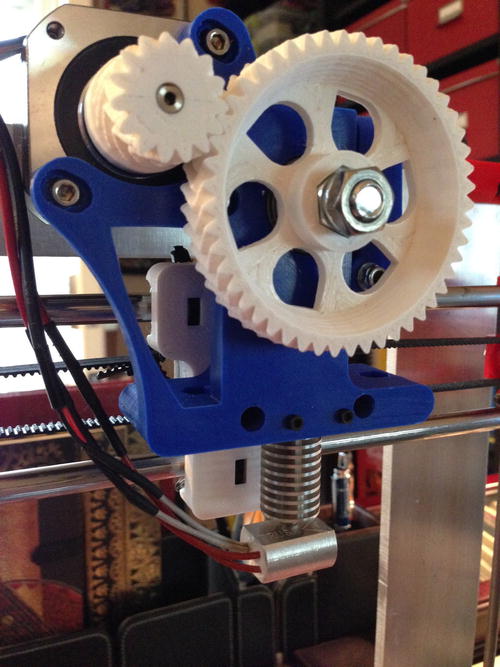
Figure 1-21. Extruder assembly (Prusa Iteration 3 with Greg’s Wade hinged extruder by misan: thingiverse.com/thing:65939)

Figure 1-22. Extruder assembly (image courtesy of MakerFarm.com)
This is just one form of extruder. There are many variants, including some that do not use a gear-drive hobbed bolt. Instead, they use a special pulley that has been machined to grip the filament. Figure 1-23 shows the special drive pulley, called an Mk7 direct drive pulley (sometimes called a direct drive gear). In fact, these extruders are also called direct drive extruders or even compact extruders, because they require very few extra parts and a small body to mount the motor. I have enlarged the photo so you can see the machined grooves for gripping filament.

Figure 1-23. Direct drive Mk7 gear (image courtesy of MakerFarm.com)
In almost all cases, extruders use a tension mechanism to help the extruder grip the filament. For example, the Greg’s Wade hinged extruder uses a door with an idler pulley (a bearing) with two springs held under tension by bolts. Similarly, a direct drive extruder for the MakerBot Replicator 2 uses a spring-loaded arm to apply pressure against the direct drive gear. Figure 1-24 shows an example of a custom extruder body made from machined aluminum by Karas Kustoms (karaskustoms.com). We will see more upgrades for 3D printers in a later chapter.

Figure 1-24. MakerBot Replicator 2 extruder body upgrade (image courtesy of Karas Kustoms)
The hot end, if you recall, is responsible for accepting the filament fed from the extruder body and heating it to its melting point. You can see one of the latest hot end upgrades for 3D printers in Figure 1-21. The bit at the bottom with the fins is a Prusa Nozzle made especially by Josef Prusa’s company (http://prusanozzle.org). I will discuss different types of hot ends and why you would choose one over another in Chapter 2.
Now that we have an idea of how the extruder heats and extrudes plastic to form objects, let us talk briefly about where all that plastic goes.
Build Platform
All 3D printers (FFF or FDM types in particular) use either a stationary or moving platform to build the object. Hence it is called a build platform. Those printers that use a moving platform isolate movement to one axis. For example, a Printrbot Simple moves the build platform on the X axis (left and right), a Prusa variant moves the build platform on the Y axis (forward and backward), and the MakerBot Replicator 2 moves on the Z axis (up and down).
The build platform (sometimes called print bed or simply print platform) can be made from wood, Lexan, aluminum, and composite materials as the base. Placed on top of this is an aluminum, glass, or composite plate called the build plate. Glass is the most common choice. It is to this surface that the first layers of the object are extruded. Some build platforms include a heater element, called a heated build plate, placed under the glass. The heated plate is used to help some filament stick to the build plate. A built platform with the heated element is called a heated build platform. Figure 1-25 shows a heated build plate.

Figure 1-25. Heated build plate (image courtesy of MakerFarm.com)
It is common practice—and indeed sometimes essential—to use another medium on top of the build platform to help objects adhere to the build plate. Like the decision to use a heated build plate, the medium used varies with the filament used. For example, some plastics adhere better to blue painter’s tape, whereas others adhere better to Kapton tape (a special heat-resistant film).
The component responsible for reading the G-codes and translating them into signals to control the stepper motors is a small microcontroller platform utilizing several components. Most notably are the microprocessor for performing calculations, reading sensors (endstops, temperature), and controlling the stepper motors. Stepper motors require the use of a special board called a stepper driver. Some electronics packages have the stepper drivers integrate, and others use pluggable daughterboards.
While most commercial printers use a proprietary electronics package, there are several types available for RepRap and similar DIY printers (RAMPS, RAMBo, Printrboard, etc.). The most common is RAMPS, which uses an Arduino Mega, a special daughterboard (called a shield), and separate stepper driver boards. Figure 1-26 shows the components for a typical RAMPS package. The photo shows the optional LCD display with an integrated SD drive that enables computerless operation.

Figure 1-26. RAMPS kit (image courtesy of MakerFarm.com)
Now that we have discussed the axes, how they are moved, the electric motors that move the component, the extruder, the build platform used to form the object, and the electronics, it is time to discuss how a frame holds all of these parts together.
Frame
The choice of frame material is another area that varies from one printer to another. The best frames are those that are rigid and do not flex when the extruder is moving or when the printer moves an axis in small increments. As you can imagine, this is very important to a high-quality print.
Early open source 3D printers (like the Prusa variants) used a series of threaded rods and printed parts to form the frame. They used two triangular frame members joined by another series of threaded rods. You can see the evolution of the RepRap variants at http://reprap.org/wiki/Build_A_RepRap.
The most recent RepRap Prusa iteration can be built with either laser-cut wood or a single sheet of aluminum. Figure 1-21 showed a single sheet aluminum version. Figure 1-27 shows an example of a wooden version of the same printer. It is actually made from melamine, which is a wood composite that offers better rigidity than plywood without the effects of humidity (swelling).

Figure 1-27. Malamine Prusa Iteration 3 frame (image courtesy of See MeCNC.com)
Another common choice for frame material is steel. The MakerBot Replicator 2 and newer versions use a special rectangular steel frame that is very rigid. Figure 1-28 shows a photo of the MakerBot Replicator 2 frame. Not only does the steel frame provide excellent rigidity, it also surrounds the entire printer—forming a perimeter frame. This is in stark contrast to the Prusa Iteration 3 that has a very minimal, mostly internal frame.

Figure 1-28. MakerBot Replicator 2 steel frame (image courtesy of MakerBot.com)
Other printers use thick acrylic for the frame components: laser-cut wood panels that are bolted together, or a combination of various materials. Aesthetics are sometimes employed so that the printer itself resembles more of a household appliance and less of a mash-up of a blender and a lawnmower.13
If you are buying a prebuilt printer or a commercial offering, you won’t have a choice of the frame materials. However, if you are building your own printer or deciding which kit to buy, you can choose the frame material. As I mentioned, the Prusa Iteration 3 variant can be found as a kit with a wooden, composite, or even aluminum frame. Whichever material you choose, the frame is the only part of the printer that isn’t directly moved. It should be as rigid as possible and provide strong anchorage for each axis.
Now that we have discussed how 3D printers are constructed, let us now look at the types of filaments that are available to use in building objects.
There are many forms of filament and more being created every year. Filament comes in a variety of sizes (usually 1.75mm or 3.0mm) and dozens of different colors. You can get filament that has a slight sheen or even a flat (think matte) filament that glows in the dark, and even filament that has small bits of metal flake to make it appear to sparkle in the light. Indeed, you can build up quite a pallet of colors to express your creativity. Filament is normally wound on a plastic or wooden spool.
![]() Note The diameter of the filament required is governed by the size of the extruder. Printers come with either a 1.75mm or 3.0mm hot end. Check your documentation before ordering new filament.
Note The diameter of the filament required is governed by the size of the extruder. Printers come with either a 1.75mm or 3.0mm hot end. Check your documentation before ordering new filament.
The most common types of filament are plastics called polylactic acid (PLA) and acrylonitrile butadiene styrene (ABS). Each type of filament has certain heating properties and requirements for build platforms. Table 1-7 lists the more common filaments available, along with their abbreviations and brief descriptions. The melting point (in this case, the temperature that the filament becomes soft enough to extrude) is listed in degrees Celsius.
Table 1-7. Filament Types

![]() Note Actual melting points for your printer may vary slightly.
Note Actual melting points for your printer may vary slightly.
No matter what type of printer you buy or build, the choice of filament will be dictated by the printer hardware. Specifically, the following components determine which filament the printer will support.
- Size of extruder and hot end
- Hot end heating characteristics, such as the maximum heat range
- Heated print bed support
The size of the extruder feed mechanism and the size of the hot end will determine whether you can use 1.75mm or 3.0mm filament. The material used to make the extruder body and the heating characteristics of the hot end will also factor into which filament you can use. Lastly, whether the printer has a heated print bed will also determine which filament you can use.
Recall a heated print bed helps the filament adhere to the print bed. Filaments that require a heated print bed (those that perform best with a heated print bed) are ABS, HIPS, nylon, and PC. PLA and other filaments with a lower melting point typically don’t require a heated print bed. However, it can be shown to help with PLA.
If you are planning to build a printer or want to be able to print with a number of filament types, you should look for a printer that has a hot end that can heat efficiently to 265 degrees Celsius (or higher), and has a heated print bed option.
Another, less frequently cited, criteria is the sort of gases that the filament exudes when heated. Some filament produces a noticeable odor when heated. Some have an odor that is neither harmful nor noxious (to some), whereas others have an odor that can cause irritation for those with sensitivity or are allergic to certain chemicals.
Some filament, like ABS, can be extruded in an open environment and are not susceptible to air movement that can cause the object to cool too quickly (none can withstand the effects of the air currents from a house fan, for example). Cooling ABS too quickly can cause print failures. Other filament, like PLA, retains heat and requires a small fan to cool. Figure 1-29 shows one example of how a fan is used when printing PLA.

Figure 1-29. Using a fan when printing with PLA
Most printers and kits on the market today are designed to print in PLA or ABS. Since ABS has a higher melting point than PLA, a printer that has a small fan to cool the filament can print ABS and PLA.
The choice of whether to print with ABS or PLA can sometimes be emotionally charged. Those enthusiasts who have perfected their printing of either choice can be quite insistent that theirs is the best choice. Rather than supply yet more rhetoric, I will present arguments for and against each. With this information, you can make your own choice. That is, provided you haven’t locked in on a printer that prints only one type of filament (not that there is anything wrong with that).
ABS is a very good choice if you plan to create objects that are going to be in close proximity to heat sources like a hot end. ABS is also somewhat flexible and can withstand forces that would break PLA objects. It is also easily modified—you can cut it with a hobby knife and glue it together with either ABS glue or acetone. In fact, ABS dissolves in acetone. You can make your own ABS glue by dissolving a small amount of ABS in acetone. As the acetone evaporates, it leaves hardened ABS that forms a strong bond. Lastly, ABS flexes well—forming strong bond layers.
However, ABS exudes a very noticeable odor that can cause some people irritation. It is always a good idea to use a fume extractor when printing with ABS. In fact, some people build special enclosures or fume hoods to vent the gases to the outside. ABS is also not as rigid or as strong as PLA and can wear more quickly than PLA. For example, gears are best made from PLA, since gears made from ABS can wear out quickly. If your printer came with ABS gears, check them often for wear, and replace them when tolerance becomes too great (the gears have excessive play).
Lastly, ABS requires a heated print bed and Kapton tape or similar for the best bond. This fact alone makes ABS harder to print objects with no warping. Furthermore, Kapton tape can be a bit of a challenge to get to stick to a glass plate without air bubbles or wrinkles. There are many techniques that can help, and that alone should be enough to conclude ABS is more difficult to use.
PLA is a very good choice for those who plan to use their printers in their home or office. The odor it exudes smells a lot like pancakes, so unless you abhor that type of breakfast food, it is not an unpleasant experience. PLA is harder and more rigid, making it a good choice for components that must be strong and do not permit too much flexing. It is recommended to use a fan when printing PLA. A fan forces air over the filament as it is extruded. This helps the filament cool more quickly, forming a stronger bond and reducing lift. PLA is also more forgiving when it comes to adhering to the print bed. PLA adheres well to common blue painter’s tape, which is much easier to apply than Kapton tape. The ease of printing makes PLA a good choice for beginners.
However, since PLA does not flex well, it isn’t a good choice for clamps and similar objects that must flex. Also, since PLA has a lower melting point than ABS, PLA is not a good choice for extruder bodies and similar parts for printers that print ABS.
So, which is best? That depends. If you are starting out, you might want to stick with PLA until you’ve mastered some of the calibration techniques for achieving high-quality prints. On the other hand, if you want to build things that you can customize or use adaptive prototyping,14 you may want to choose ABS. Again, it is your choice, and now that you know the major ins and outs of each, you can make an educated choice.
You may be wondering if it is possible to switch from one type of filament to another. The answer is simply, “Yes, you can.” The only issue is making sure the old filament is completely removed from the nozzle before loading and using the new filament. The same is true for changing colors of filament, as we will see in a later chapter.
Now that we’ve explored the software, hardware, and filament types used in 3D printers, I want to set some expectations for you if you are just entering the world of 3D printing.
What You Can Expect from a 3D Printer
If you have never owned a 3D printer or are experiencing 3D printing for the first time, there are some expectations you should consider adopting. The following are areas where most novice 3D printing enthusiasts experience disappointment, or shall I say less than ideal enthusiasm. I discuss each in the following paragraphs.
- Ease of use
- Print quality
- Reliability
- Maintenance
These areas may seem intuitive, but there are surprises awaiting you if you do not consider each as you plan your purchase or learn to live with what you have. Don’t be tempted to give up and sell your printer or force the vendor to accept it in a return (most will not anyway). I’ve seen a number of incomplete printers, and printers with very low use, for sale. I often wonder if they are for sale because the owners’ expectations of the 3D printing experience are misguided. Perhaps the following will help you avoid a similar fate.
Ease of Use
This is the one area where things can go wrong quickly. If you’ve read or otherwise been convinced 3D printers are easy to use, you should reevaluate that assessment. The CAD software alone can be a challenge to learn and master. Vendors like MakerBot have achieved a high level of user friendliness, but that can be deceiving. You still must know where to find objects to print (Thingiverse) or learn how to use CAD software.
Aside from the software, some 3D printer vendors claim “click and print” capability, which is a bit misnamed. Even the best, most reliable 3D printers require a certain amount of calibration and maintenance to achieve good prints every time (which is unrealistic because there are so many things that can go wrong).
Ease of use, therefore, is a qualitative term. If you are already an experienced 3D printing enthusiast or if you enjoy tinkering, adjusting, upgrading, and general fiddling with hardware, the vast world of RepRap variants will seem like a treasure trove. On the other hand, if you are just starting out or do not have the patience (or skills) to tinker with your printer to get it to print well, you will want to steer clear of DIY kits and RepRap-like variants, and instead choose a well-established commercial option, like a MakerBot Replicator 2.
Once again, even the best printers require a certain amount of work to get the most out of them. Keep this in mind and avoid the temptation to blame the vendor when things don’t work so well. Most likely the problem is something you have forgotten to do, or do not know must be done. For example, leveling (tramming) the print bed is often overlooked; this is the source of a host of print failures that can be corrected by the very simple process of adjusting the print bed.
![]() Note The term “leveling” isn’t a correct term. We don’t level the bed, as in making it even with the horizon (or floor); rather we make the print bed the same distance from the X axis across the bed. That is, the hot end is the same distance away from the print bed at all locations. While tramming is the correct term, many vendors, including MakerBot, use “leveling” and “tramming” interchangeably.
Note The term “leveling” isn’t a correct term. We don’t level the bed, as in making it even with the horizon (or floor); rather we make the print bed the same distance from the X axis across the bed. That is, the hot end is the same distance away from the print bed at all locations. While tramming is the correct term, many vendors, including MakerBot, use “leveling” and “tramming” interchangeably.
This category is one that can cause even the most hardened 3D printing fan consternation. Many things can contribute to poor print quality, so sometimes it is hard to know where to start to diagnose and correct the problem. Indeed, there are 3D printer reviews I’ve read that rated the quality of printers based on skewed results. In one case, I noticed a clear indication that had the author or tester followed a few simple precautions, the print quality would have been better than what was reported.
What this means is you cannot expect to unbox (or assemble) your printer, click Print, and see a finished, perfect object appear before your eyes. You must start out with relatively low quality settings, modify them to perfection while calibrating your printer, and then increase those settings in increments until you achieve a good print.
One major factor to consider is the hardware itself. For example, a commercial printer is unlikely to arrive with incorrectly installed or damaged components. For example, building a RepRap Prusa Iteration 2 requires the use of 8-millimeter or 5/16-inch threaded rods for the Z axis. If the rods are not perfectly straight, and the threading is wound incorrectly (I once found a rod where the threads were deeper on one side than the other), you can experience Z wobble, which produces a washboard affect (the sides are not perfectly flat).
Similarly, the build platform must be level with the X axis. Adjusting it so that it is level (again, called tramming) requires moving the extruder to each corner of the build platform, and raising or lowering the print bed in that corner until the nozzle is the same distance from the print bed in all four corners (assuming the build plate is flat). Some printers are easier to tram than others. For example, the MakerBot Replicator 2 has an automated process that moves the extruder for you, whereas most printers require you to move the print head with either a printer controller application or through an LCD interface. However, you can move the axes by hand if the printer is powered off and you do not move them too quickly. Moving the axes quickly can cause the stepper motor to generate electricity and feedback through the electronics.
There is much more to consider with respect to hardware, and we will see more of this in other chapters. For now, keep in mind that print quality is something you must earn through careful calibration and attention to detail. The ease of which depends largely on the capabilities of your hardware and your willingness to tinker to perfection.
Another area that can sometimes be an issue is reliability. Even if you devote the proper attention to detail to get the printer calibrated and ready to print, you can sometimes experience hardware and software failures—especially over a relatively short period of use.
One such example is the X axis ends on one of my Prusa Iteration 2 printers. The part cracked, causing a host of random print quality issues. I replaced it, only to have it crack again. I finally fixed the problem by grafting a brace for the affected area. Fortunately, the part was made of ABS, making it very easy to add the brace. If it were PLA, it would have been harder to do (but not impossible).
As part of my diagnosis of the part failure, I made sure that the smooth rods that the part rides on were straight and that everything on the axis was aligned properly. The part is simply too fragile for long-term use. You may find that this is the case for a number of different printers.
Another example is the routing of the X axis wiring on some MakerBot Replicator 2 machines can break over time due to a stress point. Should the wire break, your printer will become inoperable. Careful research and preventive maintenance can avoid this problem.
There are more examples of reliability issues that I could discuss, but what you should keep in mind is that 3D printers are not quite to the level of the average toaster—or even the famous battery spokesrabbit. Some are more reliable than others, but all require periodic preventive and regular corrective maintenance for proper function.
Generally speaking, the more expensive commercial varieties offer better reliability than the DIY kits, but there are always exceptions. I’ve had almost no reliability problems with one of my older Prusa printers, but one of the latest ones has driven me to have a conversation or two with it. It never listens and stubbornly refuses to obey my commands.
Closely related to reliability is maintainability, or simply how easy it is to maintain and repair the printer. I’ve found my RepRap printers to be easier to work on, but they require work more often than my MakerBot Replicator 2. Indeed, regular maintenance on the RepRap printers takes about 10 minutes each time I start a series of print jobs (that day) and as much as an hour per month to clean, lubricate, and adjust. However, my MakerBot Replicator 2 requires only periodic adjustment and only 20 minutes or so to fully clean, and I lubricate it every couple of months. Similarly, the RepRap printers require regular leveling of the print bed, whereas the MakerBot rarely needs any adjustment.
The takeaway here is if you want to be able to use a printer for hundreds of hours of relatively good printing experiences, you will want to consider how easy it is to work with the printer. If the vendor doesn’t provide examples, how-tos, and the like for maintaining their printers, be sure to ask so that you know what you are getting into. Regardless, you should consider it your job to do certain preventive procedures (e.g., cleaning, lubricating) as part of your ownership experience.
Summary
If you are thinking there is a lot more to 3D printing than you originally thought, you’re right on track. Most articles and blogs about 3D printing barely cover some of the fundamentals discussed in this chapter. Indeed, most focus on the tool chain, and heighten the reader’s expectations by convincing her about all of the wonderful things she can print. While not expressly a fairy tale, this is only part of the knowledge you need to become successful in 3D printing. However, in this chapter I provided a lot more information about the hardware and how it works. As you will see in later chapters, this information forms the basis for understanding how to get the most out of your printer.
In this chapter, we discovered how 3D printers work and what software is required, and learned about the hardware components and the different types of filament available. I also presented some sound advice for setting expectations for your printing experience and how to get started with exploring the exciting world of shared objects (things).
In the next chapter, I discuss your options for getting a 3D printer. If you already have a completed 3D printer, you might want to skim the next chapter. I think it is still valuable to learn what options you have, in case you decide to make 3D printing a hobby.15
___________________
1Most range in price equivalent to laptop computers; the more features it has, the more expensive it is.
2At least one of my printers is in a perpetual state of pending upgrade. There seems to be no end to the ways you can improve some printer architectures.
3For more information, visit http://en.wikipedia.org/wiki/3D_printing.
4I limit our discussion to printers that cost no more than about $3,000.00 USD. Any more than that amount, and you’re in the commercial and manufacturing realm.
5Like fishing line, or as my wife says, “fishing twine.”
6The box I use to store my failed prints has once again proven that the gas law reigns supreme (also known as the container maxim: all containers will eventually fill to capacity regardless of their size).
7I still have my mechanical drawing tools. I can even letter properly when forced to do so. I remember distinctly practicing my letters for hours in preparation for a final exam—much like a second grader learning to write for the first time.
8I have two reels of the same color from different suppliers, but one melts at about 8 degrees cooler than the other.
9No, it isn’t a new style of music.
10No, it isn’t spelled wrong. The name includes the number 3.
11In other words, it’s a bit nerdy or tinker-inspired. 3D printing veterans will appreciate the level of detail in feedback and printer control.
12Metaphorically speaking. Even if you open one up, you won’t see any actual gears.
13Which is precisely what my first 3D printer looked like.
14Which goes something like this: cut, drill, sand, glue, repeat.
15Like all good enthusiasts, most of us end up with several 3D printers of various designs—despite the good (and common sense) question, “Why do you need five printers?” While your spouse may never understand your answer, other 3D printing enthusiasts will.