
![]()
3D Printer Maintenance: Preventive and Corrective Tasks
Maintaining your 3D printer involves a number of simple things you need to do frequently, like checking the condition of the printer for adjustment and breakage. I refer to these tasks as “basic maintenance tasks.” Maintenance also involves more complex tasks that need to be done less often to keep the printer running well (“preventive tasks”) and tasks that need to be done when something breaks (“corrective tasks”).
These may sound like the same thing, but the there is a difference. For example, preventive tasks are things like changing the oil in your engine before the oil degenerates and the moving parts encounter excessive wear. A corrective task is changing a tire when you get a flat.
I presented the basic maintenance tasks in the last chapter. In this chapter, I will present preventive maintenance tasks that you will need to perform periodically and corrective maintenance tasks designed to help you fix things when they wear or break. The following sections describe and list some common tasks for each category.
Preventive Tasks
The goal of preventive maintenance is to execute small tasks frequently to reduce the risk and downtime of equipment failure.1 More specifically, we take steps to keep our equipment in a condition where it is operating at the highest degree of efficiency possible. This includes making sure that the equipment remains free of debris and dust, that the parts that require lubrication are lubricated properly, and that worn parts are replaced before they fail. Normally these tasks are not time-consuming, but should be performed on a regular basis.
For example, your car requires periodic maintenance. Take a look at your owner’s manual and review the maintenance sections.2 You should find a chart or list that contains many things that need to be attended to at periodic milestones based on mileage driven or time, including replacing the oil and filters, replacing tires and belts when they wear, and even lubricating the chassis.
Fortunately, there aren’t many preventive tasks required for maintaining your printer. The following sections describe the preventive tasks you should perform on your printer on a regular basis. As you will see, the frequency will vary from one printer to another, but is based on hours of use and, in some cases, influenced by the environment. I begin with the simplest preventive task: keeping the printer clean.
Cleaning the Printer
Keeping your printer clean may not sound like a preventive task. However, depending on the design of your printer, it could be a most vital task in preventing damage. That is, if your printer is a RepRap or similar design without an enclosure, dust and other debris can accumulate on the electronics, making them retain heat. Too much heat—and the electronics will fail.
Dust and dirt can also accumulate on your oiled parts, fouling the lubrication to the point of increasing friction and wear on the bearings and rods. That doesn’t mean printers with partial or full enclosures are immune to these effects. It just means the accumulation will be slower.
A bigger concern for printers with enclosures is the accumulation of small bits of plastic falling into the build area (the area around the build platform). This can include brim material, run-off filament from a print, oozing filament from the hot end, and so forth. While it would take an awful lot of plastic bits accumulating in your build area to cause major problems, you should still take the time to clean your build area periodically.
More importantly, you mustn’t allow plastic to accumulate on your build platform. Even a small amount of plastic debris on your print surface can cause problems such as uneven first layers and nozzle blockages, leading to extrusion failure.
So how do you clean a 3D printer? You can’t put it in a dishwasher or hose it down in the garage.3 In fact, you should never use any cleansers whatsoever. The only possible exception would be cleaning the outside of your enclosure. Even then, you should use a mild cleanser designed for the material of your enclosure, and do so sparingly. Check your owner’s manual for recommended cleaning procedures and cleansers.
You may be wondering why anyone would need to clean a printer. After all, they print with plastic and they don’t spew oil or other liquids or generate any particulates (well, mostly). So what is there to clean?
Strictly speaking, all of this is true. However, the accumulation of dust is a concern, as well as the accumulation of bits of plastic from part removal and print bed cleanup. Dust in particular can become a problem for exposed electronics and mechanical movements. Thus, cleaning is mostly about managing dust and debris from normal use.
The specific procedure will vary from one printer design to another, but there are several areas or subtasks you should do to thoroughly clean your printer. These tasks include the following:
- Dust and clean the frame.
- Remove dust from the electronics.
- Remove plastic debris from the build area.
- Clean threaded and smooth rods.
The frequency of when you need to clean the printer and, indeed, what areas you need to clean will depend on how dusty your environment is and how much you use your printer where debris is generated. I recommend checking the printer every 25 hours of use for things that need cleaning. At the very least, I would clean the printer every 50 or 100 hours of printing, depending on how dusty your environment is.
The frame of the printer is one area that some enthusiasts neglect. Especially so when the frame components have been properly tightened and all parts have been seated (they no longer come loose). Part of this has to do with how the frame is constructed.
If the frame is an integral structure like that of the RepRap Prusa variants—where the various moving parts are external to the frame components, the frame isn’t something you think about when cleaning the printer and generally isn’t cleaned. If the frame is a structure like that of the MakerBot or Ultimaker—where the moving parts are inside a perimeter shell, it is more likely you will notice when it needs to be cleaned.
Another factor is the material that comprises the frame components and how it is finished. Matte painted surfaces and unfinished wood surfaces tend to be less noticeable when they become dusty. Glass, polished metals, acrylic, and gloss painted surfaces will make dust more apparent. Fingerprints may be another concern for glossy finishes, and oils from your skin can smudge some surfaces. Use a soft, dry cloth to wipe away any fingerprints or smudges.
Regardless, you should remove any accumulation of dust on your printer. If your printer has an external frame or enclosure, you can use a simple dry duster to wipe away any accumulation. I find a household-dusting wand or dusting glove works best for most surfaces. If your printer has an internal frame, use a vacuum to remove dust, or use canned air or an air compressor to blow off the dust.
![]() Caution If you use a duster, stay away from the electronics! Some dusters can generate electrostatic discharge (ESD), which may damage electronics. It is best to use canned air to clean electronics.
Caution If you use a duster, stay away from the electronics! Some dusters can generate electrostatic discharge (ESD), which may damage electronics. It is best to use canned air to clean electronics.
If your vacuum has a dusting brush, you can use it, but be careful using it around any exposed electronics or ports. You should also avoid removing the oil or grease from any of the axis movements while cleaning. Remember, the goal is to remove accumulation of dust, not to sanitize it for food consumption.4
If your printer has clear acrylic panels or similar windows, you can remove fingerprints and smudges with a few drops of water applied to a soft cotton or microfiber cloth. You may use acrylic-safe liquid cleaners, but you should apply the spray to the cloth first. Never spray anything directly onto your printer. There are too many areas that can be contaminated.
![]() Tip You should never use any liquid cleaners on your printer frame unless expressly recommended by your vendor.
Tip You should never use any liquid cleaners on your printer frame unless expressly recommended by your vendor.
The electronics on your printer must also be free from dust and debris. If you allow dust and debris to accumulate on your electronics, you could risk them overheating because the dust can act as insulation. Too much heat and the electronics can fail. Admittedly, it would take a lot of dust to become a danger to some components, but that is no excuse to ignore the danger altogether.
However, cleaning electronics is not as easy as cleaning the frame. Electronics are very sensitive and most dusting devices use static to attract dust. Thus, you should never use anything other than compressed air to blow off the dust.
I like to use a can of compressed air known as canned air. It emits a concentrated blast of air that is very effective at removing dust and small debris. However, you should be aware that some canned air suppliers use chemicals in their products. Those that do are not generally harmful to electronics, but always check the label for applicability before using it to clean electronics.
You should also remove any debris that falls into your electronics. Use a pair of ESD-safe tweezers to remove the larger pieces that cannot be removed by using canned or compressed air.
An electronics enclosure can help with dust build-up. If you choose to use an enclosure for your electronics, be sure to use one with sufficient ventilation or a fan to circulate air over the electronics.
If an air compressor is not practical (you cannot fit it into your work area or it’s too noisy), canned air may be your only choice for cleaning away dust and debris without touching the device. If you use canned air to clean your printer and other electronics, and you clean often (or have many devices to clean), you could find yourself using up a can of compressed air quickly. Given the expense of canned air, you could be spending a significant amount of money keeping a supply of canned air on hand.
There is another option. Canless Air Systems5 makes a device called the O2 Hurricane. It is about the size of a medium-sized canned air, cordless, and generates a burst of air using a miniature turbine. The battery life is about 15 minutes, but it recharges quickly. It is a bit louder than canned air, though. However, it is safer for the environment because you won’t have to dispose of the canned air empties.

Unlike canned air, you can use the O2 Hurricane in any position and it won’t accidentally eject moisture in the form of the propellant and chemicals found in some canned air products. Also, the device isn’t quite as powerful as canned air, but it is more than suitable for periodic dusting. For devices with heavy dust accumulation, canned air may be a better choice. Since I clean my devices before dust becomes a problem, the slightly weaker power is not an issue.
The cost of the O2 Hurricane is a bit steep at about $80–$100, but if you use a lot of canned air, it may pay for itself in a short amount of time.
One area that can become littered with debris over time (as well as dust) is the build area. As you use your printer, small pieces of filament will be discarded from excess extrusion (before and after a print), which can fall into the build area. If you print with a raft, brim, skirt, or even ABS juice, it is possible for small fragments to break off and also fall into the build area.
While none of these pose an immediate threat to your printer, you should take some time to periodically clean out the build area. I like to vacuum after each day I use the printer. If you use your printer only occasionally, you may not need to vacuum as often. I would recommend cleaning the build area at least once every time you change or clean the print surface. That is, do it weekly.
The best way to do this is to use a small vacuum to remove the debris. I use a long, flat attachment that can reach under the build platform. If your build platform can move in the Z axis (up and down), raise it so that you can vacuum underneath it.
![]() Caution Take care when vacuuming your build area. Some vacuums can cause ESD, which can damage electronics. For this reason, some people prefer to use canned air or a compressor to blow out the debris.
Caution Take care when vacuuming your build area. Some vacuums can cause ESD, which can damage electronics. For this reason, some people prefer to use canned air or a compressor to blow out the debris.
You should also take some time to vacuum the area around your printer and the floor underneath your desk or workbench. As I mentioned earlier, the small particles can pose a threat to small animals.
Most printers use smooth rods as guides for linear or smooth bearings in the axis mechanism. These rods are typically lightly oiled. Some axes also use threaded rods to move the carriage or axis components. In some cases, you may find printers in which the threaded rods are coated with a layer of grease.
Smooth and threaded rods are among the first things in your printer to require cleaning. This is because they have a fine layer of lubrication, which traps dust and small debris. Figure 10-1 shows what this accumulation looks like. Notice that this accumulation is at the minimum range of the axis movement.

Figure 10-1. Dust accumulation on a smooth rod
Smooth rods need to be kept free of dust and debris. But doing so requires you to clean them often. If your printer is designed such that the rods are exposed, you should check and clean them at least weekly. If your printer is designed such that the rods are not exposed (they are inside an enclosure), you may not need to clean the rods as often. In that case, you should check and clean them whenever you clean or replace the print surface.
Keeping the smooth rods clean prevents too much accumulation that could damage the seals on some bearings. In fact, those bearing seals are designed to keep dust out.
To clean smooth rods, use a lint-free cloth to wipe away the accumulated dust and debris at each end of the rod. Figure 10-2 shows an example of how the debris can build up at the end of the axis. Notice the area inside the circle. Notice also the use of a cloth to wipe away the accumulated dirt.

Figure 10-2. Accumulated debris at axis ends
Horizontal smooth rods are shown in these photos, however, the vertical smooth rods should also be cleaned but may not get as dirty since dust tends to settle on horizontal surfaces. Be sure to check under the axis for debris. If your printer design permits you to get to this area with the axis raised, you should clean it.
To clean the rest of the smooth rod, fold the cloth so that a clean area can be wrapped around the rod. Slide it up and down the axis to remove any additional debris. Figures 10-2 and 10-3 demonstrate this action.

Figure 10-3. Cleaning smooth rods with a cloth
You should slide the cloth away from the carriage riding on the axis. Clean one side of the axis, move the axis into the cleaned area, and then clean the other side.
Cleaning the threaded rods is a bit more problematic—especially so if the threaded rod is lubricated with grease. In this case, I recommend cleaning the threaded rod only when needed. That is, when the grease becomes dark or shows a lot of accumulation of dust and dirt. In that case, you may be able to use tweezers to remove the majority of the dust (the grease tends to make it clump). If your threaded rods are exposed, this could occur more frequently.
However, if your threaded rods are lubricated with oil and made from steel (including the nut), like what is commonly found on RepRap printers, the threaded rods can become dirty after only a few hours of printing. In most cases, the rods may turn dark as the oil becomes contaminated. While some may feel this doesn’t warrant cleaning so long as the rods remain lubricated, I still like to keep them clean.
To clean the threaded rod, use a lint-free cloth coated with a small amount of the same oil or grease you use to lubricate the threaded rod. You might want to use a disposable glove to avoid getting grease on your hands. Check your vendor documentation for the specific lubrication needed. Figure 10-4 shows the application of a small amount of lubrication to a lint-free cloth. You don’t need much—a small, 20cm circle is plenty.

Figure 10-5. Cleaning threaded rods
![]() Note You can also remove your threaded rod to clean it. In this case, you can use a drill to lightly grip the threaded rod and turn the rod slowly to clean the valleys. However, you should be careful to avoid damaging the threads. You also will need to realign your Z axis and level your print bed. You can use more oil this way, because you don’t have to worry about getting it on the plastic parts. Just make sure you wipe it clean before reinstalling.
Note You can also remove your threaded rod to clean it. In this case, you can use a drill to lightly grip the threaded rod and turn the rod slowly to clean the valleys. However, you should be careful to avoid damaging the threads. You also will need to realign your Z axis and level your print bed. You can use more oil this way, because you don’t have to worry about getting it on the plastic parts. Just make sure you wipe it clean before reinstalling.
When you are ready, move the axis to either the maximum or minimum position. There are two ways to clean threaded rods: 1) power-off the printer and wrap the cloth around the threaded rod, and then slowly move the axis by hand (this will rotate the threaded rod, allowing the cloth to remove any excess dirt, debris, and lubrication); or 2) power-on the printer and wrap the cloth around the threaded rod, and then use either printer controller software or the utility menu of your printer to move the axis away from the cloth. Figure 10-5 shows the proper positioning of the cloth to clean a threaded rod. Notice that I placed the cloth under the axis. As the axis moves, so too will the cloth.

Figure 10-4. Cloth with lubrication for cleaning smooth rods
If you chose the second option—cleaning the threaded rod while moving the axis with the printer powered on—you should take care to avoid obstructing the axis movement. While they may seem tiny, the stepper motors are powerful enough to injure you if you get your hand caught in the mechanism. Thus, you should move the axis away from your hands. The benefit of this option is that it is faster, but it requires extra caution and should not be attempted unless you are comfortable and understand how to move the axis in the correct direction.
![]() Caution Always move the axis away from your hands and toward the endstop.
Caution Always move the axis away from your hands and toward the endstop.
Once you have cleaned the threaded rods, be sure to lubricate them as described in the next section.
WHAT ABOUT TRACKS AND V-CHANNELS?
If your printer uses an alternative to smooth rods, such as V-channels or tracks, you need to keep them completely free of debris. Unlike some bearings that have seals that can push dust away, channels and tracks generally do not have anything to push away debris.
Dust may not be a problem, but small pieces of filament can be. That is, if a piece of plastic falls into the channel or track, it can cause the carriage to bounce over the obstacle, thereby shifting the axis momentarily. If the piece is large enough, it can cause the axis to stop—or worse, derail.
Thus, you should keep your V-channel and tracks clean, checking them before each print and cleaning them whenever you find any debris.
Lubricating Moving Parts
All 3D printers have metal and other parts that need lubrication. Some are designed to use grease; others light oil, and others still are constructed so that they contain some form of lubrication. For example, some lead screws and threaded rods require grease, some bearings without seals require light oil, and sealed bearings have lubrication inside the seals. There are also bearings that are impregnated with oil in the manufacturing process.6 What matters most here are the smooth rods and bearings as well as the threaded rods and nuts.
Threaded rods and lead screws typically require either synthetic grease (e.g., PTFE) or lithium or similar grease. As I mentioned in the previous section, you typically do not need to change this grease often. In fact, some vendors suggest doing so after 50 or more hours of printing. I recommend checking the grease every 25 hours or so and replacing the grease every 100 hours.
To change the grease, we first clean away the old grease, as described previously, and then apply new grease using a disposable glove. Use your finger to dip a small portion of grease (about 10mm in diameter) and apply the grease directly to the threads, pressing the grease into the threads over about a 30mm to 40mm section. You do not have to grease the entire section—that would be way too much. A small amount will go a long way.
I like to position the axis to its maximum position, and then apply the grease behind the carriage. I then move the axis through its full movement several times to distribute the grease. Clean away any excess at the minimum position. Figure 10-6 shows an example of applying grease to the lead screw in a MakerBot Replicator 2.

Figure 10-6. Applying grease to lead screw
Smooth rods may also need lubrication, depending on what type of bearings you have. If you have bearings that require lubrication, you should apply the lubrication directly to the bearing. Follow your vendor’s documentation for doing this. Newer printers use self-lubricating bearings. Regardless, I recommend cleaning the smooth rods as described previously. Figure 10-7 shows an example of a thrust bearing that is not sealed. This bearing will require grease and should be monitored for proper lubrication every 25 hours.

Figure 10-7. Unsealed bearing
When working with 3D printers, most bearings are designed to support loads perpendicular to the shaft on which they are mounted. Thrust bearings are designed to support loads parallel to the shaft. Thus, thrust bearings are used at the end of the rod or through a mounting plate.
On the other hand, if the bearings are self-lubricating, you only need to keep the smooth rods lightly oiled. That is, you want the smooth rod to be damp with oil, but not so much that the oil runs or is visible. Most printers have bearings of this type. Thus, I present a method for lubricating the smooth rods.
Take a lint-free cloth and apply a dozen or so drops of the oil recommended by your vendor. I use light machine oil. Figure 10-8 shows the proper amount of oil. Unlike the cleaning process, we need enough oil on the cloth so that it will transfer to the smooth rod.

Figure 10-8. Applying oil to lint-free cloth for lubricating smooth rods
Once you have the oil on the cloth, wrap it around the smooth rod and move it back and forth. This is the same process as cleaning the smooth rod, but this time we have more oil on the cloth—enough that it will transfer to the smooth rod and distribute evenly. Figure 10-9 demonstrates the technique.

Figure 10-9. Lubricating smooth rods
Do this on each side of the carriage. If your axis uses multiple rods, lubricate all of them, checking the cloth to make sure you are not picking up dirt. If you see dirt on the cloth, fold it and continue wiping until the cloth comes away clean. Next, move the axes through its full range of movement a few times. Remove the cloth and examine each end and wipe away any excess oil.
Remember, if you are using bearings that do not need lubrication, you only need to keep the smooth rods lightly oiled. You know you have the right amount if there is no excess and the smooth rod feels slick to the touch. If you ever encounter oil on the build plate or elsewhere, you have used too much oil on your smooth rods.
The frequency for lubricating the smooth rods varies based on when you clean them. That is, you should lubricate the smooth rods after each time you clean them. This is because the cleaning process will remove much of the lubrication. For printers that have smooth rods that do not need cleaning, I recommend cleaning and lubricating them every 50 hours of printing.
![]() Tip If your printer uses tracks or grooved channels, the wheels or rollers that ride in these tracks or grooves may need lubrication. If they use sealed bearings, you may not need to lubricate them at all. It is best to check your documentation to make sure.
Tip If your printer uses tracks or grooved channels, the wheels or rollers that ride in these tracks or grooves may need lubrication. If they use sealed bearings, you may not need to lubricate them at all. It is best to check your documentation to make sure.
There is one other possible area where you may need lubrication. Printers using belts or chains to move axes use one or more idler pulleys in the mechanism. These idler pulleys may need lubrication. For example, the MakerBot Replicator 1, 2, and 2X have an idler pulley for the X axis that must be lubricated periodically. MakerBot suggests using the same grease for the lead screw (PTFE). The best way to apply the grease is to use a pair of tweezers with a pea-sized blob of grease. Use tweezers to transfer the grease onto the idler shaft, and then move the idler pulley back and forth to distribute the grease. Figure 10-10 shows the location of the idler pulley.

Figure 10-10. Applying grease to idler pulley (MakerBot Replicator 1, 2, 2X)
If your idler pulley requires lubrication (check your documentation), I recommend cleaning the idler pulley and reapplying the grease at the same interval you clean and lubricate the lead screw or threaded rods. That is, check it every 25 hours and clean and reapply grease every 100 hours.
WHAT ABOUT MY PRINTER?
The descriptions and procedures presented in this chapter are intentionally vendor neutral.7 Whereas you should be able to use this information to service your printer, you may want to check your manual for maintenance tasks. Some vendors provide online technical support for maintenance tasks. The best vendors present how-to articles and videos to help you service your printer. Even if your vendor does not provide how-to articles and videos, you should be able to find details on the type of lubrication used on the moving parts. In the rare event you do not find this information on the vendor’s web site (or in your manual), contact the vendor to ask.
You should replace any worn part when you discover the problem. As I discussed in the last chapter, periodic inspections can help you find parts that are worn. Whenever you discover a worn part, you should replace it as soon as you can. Continuing to use your printer with worn parts can risk problems with print quality. Some of the most common wear parts include the following:
- Print surface treatments
- Gears and gearboxes made from plastic (printed or otherwise)
- Fans
- Belts
- Bearings
Of course, print surface treatments wear most frequently, and we have already discussed the specifics of inspecting and replacing the print surface. Likewise, we have discussed the signs to watch for wear on gears. Recall that wear normally manifests as dust in the gear valleys and rounding of the teeth. I discuss printing your own replacement gears in the next section.
Fans are one of my pet peeves. I’ve had numerous electronics projects and a good number of manufactured gear—some very expensive—fail because a small, insignificant fan stopped working. Fans will most likely broadcast potential trouble in the form of excessive noises like high-pitched squeals, rattles, or slow start up. When you encounter these symptoms, replace the fan as soon as you can. Fortunately, most fans used on 3D printers are typically used in only two areas: the extruder and the electronics. Thus, they are easy to get to and normally easy to replace.
Belts are also wear items that may need replacing, but they wear at a much slower rate than gears. Recall that when belts wear, they can stretch—eventually fouling the mating of the teeth and the drive gear. In rare cases, belts can strip teeth or break. However, these are very unlikely events. In fact, unless you use your printer for hundreds to thousands of hours, you may never encounter a problem with worn belts. However, I have seen this happen at least once.
Bearings wear down as well, but like belts, they are unlikely to need replacing. However, when bearings wear, they can start making noises (from lack of lubrication), have excessive play, or even bind or break apart. These events are even less likely than worn belts, but again, if you use your printer a lot or if you fail to keep the bearings lubricated (or they fail from a manufacturing defect), they can fail. Check the bearings at least every 100 hours to ensure that they are in good order.
Now that we have seen some of the maintenance tasks you should perform regularly, and before I get into describing the common corrective tasks you may have to perform, I want to discuss the subject of spare parts that you should have on hand for things that wear or may break.
Got Spares?
Having a store of spare parts is key to keeping your printer running over the long-term. Spares are one of the things a lot of RepRap manuals and blogs discuss, but they often focus on only those plastic parts that you need to maintain RepRap printers. Sadly, some vendors do not mention spare parts at all. That is unfortunate because there are a small number of spares you may want to have on hand if you plan to use your printer for many hundreds of hours. Fortunately, some vendors do offer spare parts for sale. Two of the best examples of ample spare parts availability are Ultimaker and Wanhao.
Ultimaker (https://www.ultimaker.com/t/spare-parts) offers a long list of spare parts you can buy, including fans, belts, gears, and extruder parts—everything you need to keep your printer in top shape.
Wanhao sells printers similar to MakerBot printers. Wanhao (http://wanhaousa.com/pages/parts) offers a complete list of replacement parts that even include many of the molded parts, like X-ends and more.
Don’t assume that just because your vendor doesn’t offer spares that you will never need to repair your printer. Even if you print only a few hours a week, you will eventually need a spare part. A lot depends on how well the components in your printer were made, how often you perform the required preventive maintenance, and whether events occur that can damage a component.8
In my experience, I’ve had some printers fail as early as within 10 to 20 hours. In one case, a new part failed within an hour. And one of my printers with several hundred hours has yet to fail. However, I must clarify that I replaced a number of worn parts before they failed. The point is that sooner or later you are going to have to replace something that has worn out.
There are two kinds of spares that you should keep on hand. First, there are those components that you can print yourself. This applies mainly to RepRap printers since they are composed of parts printed by other 3D printers. Second, there are electronics and hardware components you should have on hand.
I suggest certain spares in the following sections. The lists are based on my experiences with RepRap, MakerBot, and other commercial-grade printers. The lists for your specific printer may vary from what is presented here. However, you should be able to use the lists to construct your own spares inventory.
But take some care to think through what you need. Taken to the extreme, you could end up with enough parts to build a second printer. For example, the last time I decided to build a RepRap printer, I found that I had everything I needed except the build platform. Of course, once a part has failed I tend to keep a second one on hand just in case it fails again.
![]() Tip I suggest setting a budget for buying spares. Sometimes a spare part may be too expensive to keep on hand. For example, the electronics board for a MakerBot Replicator is very expensive and (fortunately) rarely fails. On the other hand, if you rely on your printer for your business, you may want to have one on hand so that you don’t encounter significant downtime.
Tip I suggest setting a budget for buying spares. Sometimes a spare part may be too expensive to keep on hand. For example, the electronics board for a MakerBot Replicator is very expensive and (fortunately) rarely fails. On the other hand, if you rely on your printer for your business, you may want to have one on hand so that you don’t encounter significant downtime.
As I mentioned, printed spares are mainly for RepRap printers. However, some commercial- and professional-grade printers use parts that can be printed. For example, you can print new Mk7 Stepstruder (thingiverse.com/thing:53125) extruder bases and idler arms for the MakerBot Replicator 1, 2, and 2X printers.
Printing spares for your printer can be a lot of fun. I recommend printing a set of spare parts as one of your first noncalibration tasks. Not only will you learn a lot about how best to use your printer, you will gain a set of spares to keep the printer running. In fact, you can get carried away to the point where you’ve printed an entire set of plastic parts—enough to build a new printer. This was one of the main goals of a RepRap printer.
But you don’t have to go that far. You need to only print those parts that wear or are prone to breakage. I list these parts in the next section.
Recommended List of Spares
In this section, I present a set of spares you should consider having on hand. If you have the budget to buy a complete set of spares, you should do so. However, if you are budget conscience, you may want to consider finding a source for the spares and saving that information so that when you do need the spares, you can get them quickly. On the other hand, if you are using your printer for a business or cannot afford the downtime to wait for a spare, you should consider investing in a set of spares as soon as your budget permits.
The following lists the printable spare parts that you should keep on hand. Some of these are applicable to most printers, whereas others are more specific to RepRap printers. Take some time to examine your printer and locate any similar part to determine if you can print the part or you must buy it from your vendor.
- Extruder gears: These can be a challenge to print because they must be printed with no lifting or distortion. Thus, printing gears is an excellent way to perfect your technique for eliminating lift.
- Extruder idler mount: If you are using a RepRap printer with a Greg’s Wade hinged extruder, the idler mount (also called a door) can fail over time due to stress. Other extruders may not have this problem, but like the gears, printing a complete extruder body is a good way to practice and fine-tune your printer. However, since some extruder idler mounts are easily broken, you may want to print several spares in case your backup breaks when printing a replacement.
- Endstop holders: Endstop holders can take some abuse. Most are rather flimsy, which doesn’t help. If your printer uses the same holder for all axes, just print one; otherwise, print a set.
- X-ends: The X-ends on RepRap Prusa i2 printers have been known to break from a surprisingly small amount of flex (like from a hot-end crash into the print bed). If you have a Prusa i2, I recommend printing a set of X-ends to have on hand.
- Bar clamps: These are among the most fragile parts on RepRap printers. Breakage can occur from the normal shaking of the printer—especially if the rods they support are overtightened. I recommend starting with these and printing a set of four to have on hand. Most print quickly.
- Belt clamps: Some older designs use belt clamps that can slip. The natural treatment is to tighten them down, but this act has a tendency to damage the clamps. If you have had to tighten your belt clamps more than once, I recommend printing an extra set or looking for an improved version and replacing the existing clamps with those.
- Other: I would also print a spare of any part that breaks. That is, if a part breaks, print two so that you have one as a spare.
The following lists spares that you should consider buying if you want to keep your printer running over the long-term. Once again, these may not apply to all printers, but you should buy those that do apply to your printer.
- Fans: As mentioned, fans can wear out surprisingly early. Unless your printer is built with exceptionally high-quality fans, you will eventually need a new one.
- Belts: Belts are long-wear items. I recommend getting a set once you have had to adjust the belts a couple of times after initial calibration. That is, if you printed for 100 or more hours without having to adjust the belts, and then suddenly have to adjust them, you should have a spare and replace the belt once it begins to need regular adjustment (or it breaks).
- Nozzle: The hot-end nozzle is an item that many people have as a spare so that they can change it when it gets clogged. As I have mentioned previously and will demonstrate in the next section, you can clean even the most stubborn clogs. Regardless, having at least one spare9 will help you keep your printer running should you encounter a clog that cannot be cleared with the cold pull method.
- Stepper motor: This is another long-wear item. If you want a complete spare parts supply, I recommend having one on hand. You should not need a complete set unless your printer uses different sizes for each axis (not likely, but I have seen it at least once).
- Stepper driver: The stepper driver boards are susceptible to ESD and have been known to fail on occasion. I’ve had three fail over several hundred hours. If you have a RepRap printer or a printer that has separate stepper drivers, I recommend having at least one spare.
- Endstop: Endstops are simple switches and generally have a very long life. However, if the endstop is subjected to axis crashes (where the axis runs into the endstop violently), you could damage the endstop. Given its role, I recommend having one spare.
- Electronics board: Commercial- and professional-grade printers generally have proprietary electronics boards that are usually very expensive. If your printer uses one of the more popular general options (RAMPS, Rambo, etc.), and you must rely on your printer, you should have a spare to avoid a lengthy downtime.
- Build plate: You should consider having a second build plate to allow you to swap out the build plate when the print surface needs cleaning or if you want to switch from one print surface to another.
If you cannot buy the part from your vendor directly, you will want to ensure that you are getting the correct part for your printer. If you have any concern, be sure to compare the new spare part to the matching existing part. In those cases where the new spare is somewhat different (e.g., not the same supplier), I install the new part and test it, and then put the original part back in when I confirm the replacement is compatible.
Another factor is the cost of the spare part. Some spare parts can be expensive. For example, the electronics board for a MakerBot printer is very expensive, but the electronics board for a RepRap printer is less expensive. You will need to balance the cost of the spare with the availability and time to get the part to decide if you should buy one to have on hand.
Now that I have discussed the spare parts needed for long-term use, I discuss some common and not-so-common repair tasks in the next section.
There is one other preventive task you may want to consider—upgrading the firmware. Sometimes printer manufacturers will release a new version of the firmware that has fixes or enhancements for the printing process or quality. However, most vendors do not release new versions very often. Firmware changes were common a few years ago, but not so much now.
It is generally a good idea to keep your firmware current, but I would not do it unless I encounter a need for the changes. Check your vendor’s support web site for any changes to the firmware, and read the change notes carefully before deciding to upgrade.
If you own a RepRap printer, the firmware is really up to you since it is very much a DIY affair. The same philosophy applies: don’t upgrade unless you find changes that you need. If you find that the latest variant of your firmware supports some nifty feature that you want, then upgrade; otherwise, wait. For example, if you want to add Z-probing (auto bed leveling), you will likely need to upgrade the firmware.
Corrective Tasks
This section describes a number of corrective maintenance tasks (repairs) that you may need to do to keep your printer in good working order. I have tried to keep this discussion general, but some of the examples are for specific printers or components. However, you should be able to draw parallels and knowledge from the examples should you need to fix a similar problem.
![]() Caution When repairing your printer, be sure to turn it off and disconnect it from your computer (if applicable). Unless you are diagnosing a problem, you should not need power to disassemble your printer in the course of a typical repair.
Caution When repairing your printer, be sure to turn it off and disconnect it from your computer (if applicable). Unless you are diagnosing a problem, you should not need power to disassemble your printer in the course of a typical repair.
Also, I recommend removing any access panels, enclosure panels, hoods, fans, and so forth, so that you can access the area for the repair. It is also a good idea to remove the build plate if it can be detached—especially if it is made of glass or other materials that are easily scratched or broken. It is all too easy to accidentally drop a sharp tool or part onto the print surface. Even if you aren’t concerned about the print surface treatment, the build plate itself may be fragile.
![]() Tip Whenever you work on your printer, always remove the build plate to avoid damaging the print surface with dropped tools or parts.
Tip Whenever you work on your printer, always remove the build plate to avoid damaging the print surface with dropped tools or parts.
As I mentioned in a previous chapter, it is also a good idea to gather the tools you need and place them nearby. If your printer is positioned where access to the repair area requires you to lean over the printer or reach behind it, move the printer to a place where you can access the area more easily. I use a small vintage typewriter stand with a piece of plywood on top as a work stand. Not only does this allow me to move the printer around, it also means I can push the stand out of the way if I don’t finish the repair in one sitting.
In decades past, typewriters were the laptop of the day. There were special desks designed such that the typewriter was placed in a special drawer that concealed the typewriter in the desk. I’ve seen some that pop up from under the knee area and others that pull out like a drawer.
There were also special side desks with folding arms that fit under some of the older, large office furniture. The legs are mounted on casters that rotate in all directions; at least two will be locking. The stands were typically made from metal and provided a very sturdy platform for the heavy typewriter. The following shows a typical vintage typewriter stand.

This makes the typewriter stand an excellent choice for supporting a 3D printer. You can find typewriter stands in thrift stores and antique stores, as well as online auction sites. If you look long enough, you should be able to find one in pretty good condition. If you aren’t concerned about the antiquity element, you can buy one with heavy patina, and then strip and paint it. The stand in the photo has been refurbished and looks like new.
Corrective tasks—hence, repairs—can take many forms: removing obstructions from the axis movement, cleaning out a hot end, replacing a worn or broken part, or replacing consumables like print surfaces and filters. I discuss some common corrective tasks (repairs) in the following sections.
One of the most frustrating experiences I’ve encountered is a series of extrusion failures over a short period of time. For example, not being able to complete a print without having an extrusion failure. I discussed the causes of this problem in an earlier chapter. Recall that most of these problems are caused by obstructions in some form: the filament cannot exit the nozzle, the filament tension is too high, or a foreign object has found its way into the hot end. In the last case, the object is larger than the opening in the nozzle, and hence clogs it from within. It is this scenario that I cover in this section.
If you encounter this problem and the cold pull method does not work, you may have to remove the nozzle and clean it out. There are several techniques for doing this. What I present here is the most reliable procedure, but it requires some care to execute safely.
You will need a pair of heat-resistant gloves, the proper tools to remove the nozzle, metal tongs or pliers to hold the nozzle, canned air, a butane torch, a metal trivet or heat-safe place to place the heated nozzle between the procedure steps, and two drill bits—one that is the exact size of your nozzle opening and another that is the same size as the filament chamber (1.75mm or 3mm). The procedure is as follows. I explain each step in more detail afterward.
- Remove the nozzle.
- Place the torch on a workbench in an area where there are no combustible liquids or any flammable material.
- Pick up the nozzle with a pair of metal tongs or pliers.
- Turn on the torch and turn it up to about a medium setting.
- Place the nozzle in the flame. Do not heat the nozzle more than a few seconds. You do not want to use so high a flame as to burn the plastic.
- After 10 to 20 seconds, remove the nozzle from the heat and use the larger drill bit to pull out melted plastic. Let the drill bit and nozzle cool.
- Reheat the nozzle and repeat step 6 until you cannot get any more plastic.
- Let the nozzle cool, and then use the small drill bit to clear the nozzle opening.
- Reheat the nozzle and use canned air to blow out any remaining filament.
- If you printed with ABS, soak the nozzle in acetone to remove any traces of filament.
![]() Caution Never, ever use a powered drill to drive the drill bit. We are only using the bit to grab the plastic, not change the internal structure of the nozzle. You only want to grip plastic and not remove any metal. You should practice this on a nozzle that you have considered a lost cause before trying it on your only nozzle.
Caution Never, ever use a powered drill to drive the drill bit. We are only using the bit to grab the plastic, not change the internal structure of the nozzle. You only want to grip plastic and not remove any metal. You should practice this on a nozzle that you have considered a lost cause before trying it on your only nozzle.
You may need to disconnect the heater element, temperature sensor, wiring, and so forth, to remove the nozzle. Some hot ends do not have a removable nozzle (e.g., a Prusa nozzle) and will require removal of the hot end. Others still may require you to disassemble the hot end to get to the core since the nozzle and core are all one piece. Consult your documentation for your hot end for the precise procedure for removing the nozzle.
When you place the nozzle in the flame, move it back and forth to heat the entire nozzle. I like to grip the nozzle by the bottom and let the flame flow over the body. The filament will melt quickly. Some filament may ooze from the opening. This is normal. Figure 10-11 shows how to position the nozzle.

Figure 10-11. Place the nozzle in the flame
![]() Caution You must wear protective gloves while using the torch. Proper eye protection is also prudent, as is having a fire extinguisher nearby in case something goes awry.10
Caution You must wear protective gloves while using the torch. Proper eye protection is also prudent, as is having a fire extinguisher nearby in case something goes awry.10
Next, use a drill bit that is the same size as the chamber and press it into the melted filament, and then pull it out. Don’t use a drill or electric driver for this step. This mimics the cold pull procedure, but in this case we’re using the cold drill bit to help grip the plastic and remove it. Figure 10-12 shows the proper size and position of the drill bit. You will want to use the drill bit with one hand while holding the heated nozzle with the tongs or pliers.

Figure 10-12. Proper size and location of drill bit for removing plastic
![]() Caution Be very careful when handling the heated nozzle. The nozzle as well as the tool you use to hold it in the flame will get very hot. Also, never use any form of driver or drill in this step. Use your hands to manipulate the drill bit.
Caution Be very careful when handling the heated nozzle. The nozzle as well as the tool you use to hold it in the flame will get very hot. Also, never use any form of driver or drill in this step. Use your hands to manipulate the drill bit.
Remember, you will be holding the heated nozzle with one hand and your other hand will manipulate the drill bit. Once you have removed some plastic, place the nozzle on a safe surface (e.g., a metal trivet) and allow the drill bit to cool, and then remove the plastic from the drill bit. Reheat the nozzle and try removing more plastic. Do this a few times until no more plastic can be removed.
![]() Caution The goal is to remove plastic, not reshape the interior of the nozzle. Thus, you should apply only enough pressure to grasp the filament. If you see metal shavings, you’ve gone too far.
Caution The goal is to remove plastic, not reshape the interior of the nozzle. Thus, you should apply only enough pressure to grasp the filament. If you see metal shavings, you’ve gone too far.
Once you can no longer get any plastic from inside the chamber, use the small drill bit to gently drill out any plastic from the opening. This step requires a bit of patience and the proper drill size. Be sure to get the properly sized microdrill that matches your nozzle. Figure 10-13 shows the properly sized drill bit and orientation for cleaning the opening.

Figure 10-13. Proper size and location of drill bit for cleaning opening
Don’t apply a lot of pressure here. The drill bit is very small and can break easily. You want to drill out the plastic, not reshape the opening (although you can do that if the opening has been damaged from a crash into the build plate). If this step makes you a bit nervous, that’s OK. In that case, try using a drill bit that is slightly smaller than the opening to remove the plastic, and then switch to the correct size once the opening is clear.
At this point, the foreign object should be removed. You should also be able to hold the nozzle up to the light and see a pinpoint of light coming through the opening. If you do not, repeat both drill bit steps until you do see light through the opening.
Return the nozzle to the heat again. Let it heat up for about 20 to 30 seconds, and then position the nozzle so that the opening is facing you and the chamber is facing the workbench (cement or metal floor, metal trash can, etc.) or some area that is safe for melted plastic. Use canned air to blow through the opening. Direct the air through the opening (reverse of the extrusion direction). This will remove the larger of the remaining bits of plastic, such as shavings from the drill bit.
![]() Caution Always direct the air away from your body. Hot plastic can burn your skin.
Caution Always direct the air away from your body. Hot plastic can burn your skin.
At this point, your nozzle should be completely unclogged. You should clean the nozzle thoroughly with a wire brush before reinstalling it.
If you print with ABS and indeed ABS was the filament used last, you should consider soaking the nozzle in acetone for about an hour. This will completely remove any stray bits of plastic that the previous steps missed. Figure 10-14 demonstrates this step. Notice there is enough acetone to completely submerge the nozzle. Also, the acetone is placed in a glass jar. Any acetone-safe container will work.

Figure 10-14. Soaking the nozzle in acetone (ABS only)
Now that wasn’t so bad, was it? As you can see, this procedure is not for the faint of heart. Indeed, if you have any concerns about performing the procedure, you can always take the easier route and simply replace the nozzle. Replacement nozzles are generally cheaper than an entire hot end (if it is a separate part, like the J-head hot ends), but they are not cheap by any measure.
I recommend buying a replacement nozzle first and then trying this procedure on the original. If you dig too deeply with the drill bit or experience some similar mishap, you will gain practice without so much risk.
![]() Tip Until you perfect the procedure, don’t try this procedure on your only nozzle!
Tip Until you perfect the procedure, don’t try this procedure on your only nozzle!
Replacing Broken or Worn Plastic Parts
If you own a printer that is assembled using printed parts, chances are you will encounter a situation where one of those parts will break or wear out. With RepRap printers, bar clamps, belt clamps, and endstop holders are very common sources of breakage.
Sometimes a broken part can be repaired. That is, if it is made from ABS, you may be able to cement the parts back together. But this isn’t always possible if the breakage occurred from an overtightened or undertightened part. In this case, it is possible the movement of the printer itself has weakened the part. Repairing the part may not be the best solution. In these cases, I recommend replacing the part with a new one. If the part was damaged by stress, or if it is not repairable, your only option is to replace the part.
![]() Tip You can repair ABS parts with acetone-based glue, such as ABS pipe cement. You can also repair PLA parts with a dichloromethane-based solvent glue, such as Weld-On #4.
Tip You can repair ABS parts with acetone-based glue, such as ABS pipe cement. You can also repair PLA parts with a dichloromethane-based solvent glue, such as Weld-On #4.
When parts become worn to the point that they can no longer be tightened, or they wobble or do not function correctly, you have to replace them. For example, the pivot point on the idler mount (the door) for a Greg’s Wade hinged extruder can become rounded out over time. When this happens, you may not be able to apply the correct tension to the filament. In this case, you may not be able to print until you replace the idler mount.
If you do not have a replacement part and your printer is still functional or you can secure the broken part temporarily by cementing it back together or using a zip tie or even duct tape,11 you may be able to hold things together long enough to print a new part.
Replacing the part can sometimes be a little tricky. Depending on where the part is located and how your frame is designed, replacing the part may be as straightforward as unbolting the old one and bolting the new one in its place. If the part is a subcomponent of another part, it may require a lengthier disassembly. For example, if you need to replace a part on a Prusa i2, you may need to partially disassemble the frame to get to the part.
REPLACING PARTS FOR THREADED ROD FRAMES
Printers that use threaded rods use printed parts to connect the parts together. For example, a Prusa i2 uses threaded rods that attach to plastic pieces at the ends of the rods (as well as several that attach to the center). Unfortunately, if one of the plastic pieces break, it can be time-consuming to replace it. This is especially true for pieces that mount toward the center, such as belt clamps, Z-axis clamps, idler pulleys, and Y motor mounts.
In order to replace these or other frame components, you must loosen the nuts on both sides of the threaded rod so that you can move the rod enough to get to the part. For example, to replace a bar clamp for the Y-axis smooth rods, you must first loosen all of the nuts on the rod, and then unthread the rod (left or right—whichever is closest). The figure below shows the location of the belt clamps. The arrows pointing down locate all of the nuts you must loosen or remove and the arrows pointing up locate the two bar clamps.

As you can see, there are a lot of things to remove, including ten nuts. However, you don’t have to remove all of them. You can loosen them all, and then rotate the threaded rod away from the bar clamp. For example, if replacing the left bar clamp, thread the rod to the right. It is a bit tedious because you have to turn the rod a few turns and then readjust the position of the nuts (blue painter’s tape can help here), but it is the only way to replace parts that mount on a threaded rod.
When replacing worn or broken parts, I like to save the part so that if the problem reoccurs, I can compare the failed parts to determine if the problem is the same. This not only helps you diagnose the cause of the failure, it also helps to form a pattern for wear items. That is, if you are wearing out extruder gears, you may be able to detect a pattern to the wear, such as a bent mounting bolt, an overtightened gear, or misalignment between the gears.
When disassembling your printer to remove the part, place the various bolts and nuts away from your tools so that you don’t accidentally knock one off onto the floor or drop it into the bowels of your printer. If you are working with a lot of bolts of varying sizes and lengths, make a grid on a piece of paper and label each grid with the location for the bolts. I find this step a necessity when working on smaller electronics such as phones, tablets, and laptops. It is a good habit to form and it will keep you from inserting a bolt that is too long.
A professional European car mechanic once taught me to always label bolts with their location. This is extremely important for many high-end sports cars and motorcycles, and especially older European cars. He demonstrated his point by showing me and a few friends what happened when someone reassembled a motor and mixed up some bolts. In this case, there was one bolt 5mm longer than the rest. If you inserted that bolt into one of three places and tightened it down, the bolt would bottom out against a very thin internal casing well which could break off and fall into the oil pan. Needless to say, this would also start a slow and annoying leak, but the major issue is the piece of metal floating around among the gears and pistons. Not good.
However, don’t simply replace the part and declare victory. Be sure to examine the printer before you replace the part, and think about what caused the breakage or wear. Knowing what caused the damage can help you avoid the problem in the future. For example, the idler mount for a Greg’s Wade hinged extruder can wear more quickly if you use a lot of tension on your filament. Reducing the tension to a minimal setting that still allows for successful and consistent extrusion can help make the idler mount last longer.
I also like to record the repair in my engineering journal in a manner similar to the diagnostic steps from Chapter 7. Be sure to take notes, such as which part it is, what it is made from (ABS or PLA), any pertinent events prior to the failure (such as an axis crash), and the date and time of the repair. It may also help to take photos of the part—both in place and removed. I make a note of the path and name each photo in my notebook so that I can refer to them later. I also tag each part with a piece of blue painter’s tape with a note that refers to my notebook entry. Lastly, I write my findings at the end of the entry so that I can affect the same repair should the problem recur.
One of the advantages of printing with ABS is that the parts are very easy to repair. In fact, you can join two ABS pieces together using only acetone. If you take two ABS parts and soak each piece in a small amount of acetone (in a depth of about 1mm to 2mm) for 15 seconds, and then press them together, within a few minutes the bond will be strong enough to keep the parts together. Depending on the size of the joint, the part will cure in a few hours. I like to leave the part to cure overnight.
When ABS parts break, they typically break at one or more layers. This can be caused by sheering force, too much stress, overtightening, or simply careless handling. Figure 10-15 shows a part for a Prusa i3. This is a Z-axis motor mount that was accidentally subjected to sheering force. Actually, I was disassembling the X axis and slipped. Oops. Notice how the break is along a single layer but is still attached on one side.

Figure 10-15. Broken ABS part
Since the part is still partially attached, the application of soaking in acetone won’t work. It is possible to brush the acetone onto the joint, but it is not easy to keep it from running and discoloring the exterior. However, if you dissolve a bit of ABS in the acetone to thicken it, you can brush it on without it running. Plus, brushing acetone doesn’t seem to form as strong a joint as the soaking method. Since this part is a motor mount, it needs to be as strong as an original part.
Fortunately, there is an alternative. You can use ABS cement designed for cementing ABS pipe. The most popular ABS plumbing cement has pigment, such as a purple color. This helps the plumber see where the cement is applied so that it is instantly visible whether or not the cement has been applied to the entire surface of the pipe. However, you can get clear ABS plumbing cement. Figure 10-16 shows one example of the cement. It is available from most home improvement and hardware stores that stock plumbing supplies.

Figure 10-16. Clear ABS plumbing cement
There are several advantages to using ABS plumbing cement. First, the cement is thick and easy to apply with a small flat tool like a hobby knife or wooden stirring stick. The consistency means it won’t run all over the place like pure acetone. Second, the cement dries very quickly—much quicker than waiting for acetone to evaporate. And finally, the cement forms a very strong bond. Because of these advantages, I use clear ABS plumbing cement for all ABS repairs or multipart assembly. Figure 10-17 shows the repaired motor mount reinstalled.

Figure 10-17. Repaired ABS part
Notice that you can see the joint. I was in a bit of a rush when I repaired the part, so I did not apply any finishing techniques to hide the seam. Whether you choose the acetone method or the ABS plumbing cement, you can cover the seam by sanding with fine sandpaper and brushing acetone over the surface. This will make the seam much less noticeable. You may want to consider doing this if the part you are repairing is an aesthetic element.
Extruders that use printed gears are a wear item that should be monitored periodically and replaced when needed. The type of plastic used in printing the gear will have an effect on the longevity of the gears. Gears printed with PLA tend to last longer than those printed with ABS.
Printed gears tend to wear slowly, producing a dust that settles in the valleys of the teeth. The dust isn’t a problem (but is good to clean it off once in a while), however the dust is an indication of wear. If you are seeing a lot of dust, you may want to examine the teeth for excessive wear.
One way to do this is to compare the gears to a new set. If you notice rounding or that pieces of the teeth have broken off, you will want to replace the gears. As mentioned in an earlier chapter, if there is any play in the mating of the teeth, you should replace the gears as soon as you can. Figure 10-18 shows a closeup of a gear-driven extruder.

Figure 10-18. Gears for the Greg’s Wade hinged extruder (Prusa i3)
![]() Tip If your printer came with gears printed with ABS, I recommend printing replacements with PLA. In my experience, the PLA gears wear much more slowly and are not as susceptible to damage. They also benefit from light lubrication to reduce friction.
Tip If your printer came with gears printed with ABS, I recommend printing replacements with PLA. In my experience, the PLA gears wear much more slowly and are not as susceptible to damage. They also benefit from light lubrication to reduce friction.
Notice the bolts for the stepper motor (one is hidden by the larger gear). These are set in an oblong mount that allows you to adjust the distance of the motor from the larger gear shaft. This is how you would adjust the mating of the gears in this particular extruder body. Other extruders may have similar adjustability—especially if they are variants of the Greg’s Wade extruder.
![]() Note If you decide to use a different set of gears than what your printer came with, check the number of teeth in each gear. If they differ, the gear ratio will be different, which will affect how the extruder works. You can use a different gear ratio, but you will have to change the firmware to match. See Chapter 5 for information about setting the gear ratio in the firmware.
Note If you decide to use a different set of gears than what your printer came with, check the number of teeth in each gear. If they differ, the gear ratio will be different, which will affect how the extruder works. You can use a different gear ratio, but you will have to change the firmware to match. See Chapter 5 for information about setting the gear ratio in the firmware.
To replace the gears on a typical printed gear-driven extruder, I recommend first unloading the filament. This will allow you to move the gears freely, with the exception of the resistance of the stepper motor. Follow the procedure listed in your documentation to unload the filament. This will involve heating the hot end and then reversing the extruder motor until the filament can pull clear.
Once the filament is unloaded, you can loosen the bolts for the gears. The easiest way to remove the gears is to remove the stepper motor. Typically, the small gear is attached to the stepper motor. Once removed, you can loosen the setscrew (called a grub screw) and remove the small gear. You can then remove the nut holding the large gear to take off this gear. Reverse the procedure to install the new gears.
If your extruder has an adjustment feature for the stepper motor mount, be sure to adjust the stepper motor so that the gears mate well. That is, the peaks and valleys close without gaps and there is no play in the gears. To check this, try to turn the gears in opposite directions—first one way and then the other. If there is any play, try moving the stepper motor closer to the large gear.
Replacing Belts
Recall that the belts used in your printer are designed to have teeth or grooves that allow the drive gear to move the belt consistently. If the belt is worn or there are teeth missing, the belt can slip and cause problems with axis shift. If you have monitored your printer over time and notice that the belts become worn (or worse, break), you should replace the belts. The procedure for replacing the belt varies based on the type of belt used.
Some printers use a length of belt with the ends secured to either the carriage, whereas others use continuous or closed belts (they have no break). Most RepRap and similar printers use a length of open belt secured at each end (for example, the X-axis belt for a Prusa i3). MakerBot and other manufactured printers use continuous belts. Some printers use closed belts without clamps. Check your printer manual or the vendor’s web site for the specifics on replacing your belts.
![]() Note Belts are typically a long-wear item. Depending on how much you use your printer, you may never have to replace the belts. You may have to adjust the tension periodically, but replacing belts is normally for those who use their printers for hundreds of hours per month. I include the procedures in this chapter for completeness.12
Note Belts are typically a long-wear item. Depending on how much you use your printer, you may never have to replace the belts. You may have to adjust the tension periodically, but replacing belts is normally for those who use their printers for hundreds of hours per month. I include the procedures in this chapter for completeness.12
Open belts are easier to fix. In this case, you need only to loosen any automatic or manual tensioner, disconnect the belt at both ends, and then pull it out. To install the new belt, thread it over the drive gear and idler, and then attach the ends. You should pull the belt as tight as possible before securing the second end. If you find there is too much slack in the belt—your tension adjustment is at its maximum position—you should set your tension mechanism to its minimum settning then remove one end and pull it tighter before securing it.
Replacing Closed Belts
Closed belts can be a bit more difficult to replace. This is because the belt must be removed from the axis mechanism by partially (or completely) disassembling the axis.
If the axis mechanism can be disassembled without removing it from the printer, things aren’t so difficult; but if you must remove the axis mechanism, be prepared for a potentially lengthy repair. I recommend taking your time and making notes (assuming your documentation doesn’t cover this procedure) so that you can reassemble the mechanism properly.
I will use the closed belts in the MakerBot printers as an example of one of the more complex closed belt replacement tasks. Other printers will require similar steps to replace the belt. Due to the very specific nature of the mechanism, refer to your printer documentation, online support articles, or community member advice for the specifics of replacing the belts in your printer.
Figure 10-19 shows the closed belt for the X axis in a MakerBot Replicator 2/2X. The photo is taken from above. Interestingly, the belt is the same configuration on the MakerBot Replicator 1 Single and Dual.
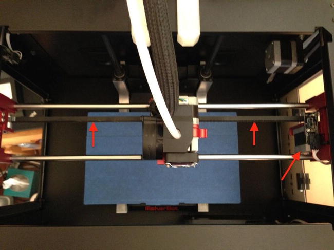
Figure 10-19. X-axis belt (MakerBot Replicator 2)
The arrows in Figure 10-19 point to the belt. Notice that it runs parallel with the X axis. To the right is the X-axis stepper motor, and on the left is the idler pulley. The stepper motor is mounted in slotted holes designed to allow some adjustment for belt tension. There isn’t a lot of adjustment; maybe 4mm total, but it is enough to compensate for normal wear.
You can adjust the tension of the belt by loosening the four bolts and pulling the motor to the right (as viewed from the front), and then retightening the bolts. This can take a bit of practice. The best way I’ve found to do this is to face the right side of the printer and use your left hand to pull the motor toward you and your right to tighten one of the bolts. Once you have one tight, you can release the motor and tighten the others.
Some printers use multiple belts on one or more axes. For example, the MakerBot Replicator 1, 2, and 2X use three belts for the Y axis; one on each side of the printer and a smaller one in the right rear. The Ultimaker machines use a similar configuration for the X and Y axes.
On the MakerBot Replicator 1, the small belt is connected to the stepper motor, which turns an intermediate shaft at the rear of the printer that has a drive pulley on each side to move the other belts in the same direction. There is a second intermediate shaft in the front of the printer. Figure 10-20 shows the left side belt for the Y axis on a MakerBot Replicator 1 Dual.

Figure 10-20. Y-axis belt, left side (MakerBot Replicator Dual)
The arrows in Figure 10-20 indicate the belt. Notice the intermediate shaft to the left in the photo. This is the front intermediate shaft. Not shown is a second idler shaft at the rear.
Figure 10-21 shows the right side belt for the Y axis on a MakerBot Replicator 1 Dual.

Figure 10-21. Y-axis belt, right side (MakerBot Replicator Dual)
Notice in Figure 10-21 that there are arrows, indicating the belt. If you look at the top center of the photo, you will see a metal loop. This is a belt tensioner, which many MakerBot Replicator and earlier printers used. Newer models do not use the tensioner. There is also an arrow in the left of the photo that shows the stepper motor that drives the Y axis.
You can see the drive belt in more detail in Figure 10-22.

Figure 10-22. Y-axis drive belt (MakerBot Replicator Dual)
Notice that the stepper motor is mounted to the side of the printer. These four bolts are in slots, which allows you to tension the small drive belt. It also allows you to remove the stepper motor, freeing one side of the closed belt. Figure 10-23 shows the outside of the printer and the four bolts for the stepper motor.

Figure 10-23. Y-axis drive belt adjustment (MakerBot Replicator Dual)
The stepper motor mount was changed in the MakerBot Replicator 2/2X. Instead of mounting to the frame directly, the MakerBot Replicator 2/2X Y-axis stepper motor is mounted to a bracket, which is then mounted to the rear of the frame. Figure 10-24 shows the Y-axis stepper motor for a MakerBot Replicator 2/2X.

Figure 10-24. Y-axis drive belt adjustment (MakerBot Replicator 2/2X)
You can still adjust the tension, but instead of loosening four bolts, you loosen only two bolts in the rear of the printer.
If you’re thinking this example is complex, you’re right. It is one of the most complex belt-driven mechanisms you are likely to encounter. I’ve seen some printers with four belts, but the concept is the same—there are intermediate shafts that allow the stepper motor to be located in a remote place, or like the MakerBot, oriented below the axis.
To replace the Y-axis belts in the MakerBot Replicator 1 printers, you first loosen or remove the Y-axis stepper motor, and then pull the belts out of each side of the X-axis carriages. Simply pull the belt toward you. There are two clamps on each side. Next, remove the intermediate shafts by first loosening the grub screws for all of the pulleys on each shaft, and then removing the shaft covers and sliding the shafts out of the printer. Be sure to catch the pulleys, because they will fall out as you remove the shaft. The belts can then be removed. No, it is not a simple procedure and, yes, it involves a fair amount of work. Figure 10-25 shows the location of the front intermediate shaft. There is a corresponding shaft in the rear. When you remove the shafts, you will push them through these holes.

Figure 10-25. Y-axis intermediate shaft (MakerBot Replicator 1)
The process is slightly different for the MakerBot Replicator 2/2X. These printers use a single intermediate shaft located at the front of the printer. There are still idler pulleys in the rear, but they ride on a separate shaft that clips into place. Figure 10-26 shows the right-side idler pulley for the Y axis. There is a corresponding pulley on the left side.

Figure 10-26. Y-axis idler pulley (MakerBot Replicator 2/2X)
To remove the idler pulley, you can use a nonmarring tool inserted in the small cavity behind the pulley to carefully pry it out. It should pop out with moderate force.
Similarly, the intermediate shaft in the front can be removed the same way. Figure 10-27 shows the intermediate shaft.

Figure 10-27. Y-axis intermediate shaft (MakerBot Replicator 2/2X)
Once the idlers and intermediate shaft are removed, you can replace the belts and reassemble in the reverse order.
The last step in the process of replacing a belt is tensioning it properly. If your printer uses an automatic or adjustable belt tensioner, be sure to loosen the adjuster completely before setting the tension. For example, the Prusa i3 has a Y-axis belt tensioner that includes a bolt to pull the belt tight.
When you replace this belt, you should loosen the bolt completely, install the new belt with as much tension as your can, and then use the adjuster to set the proper tension. Recall the proper tension should be such that you cannot pull the belt away from the drive pulley, or about one-half inch of up/down movement in the center.
MAKERBOT REPLICATOR 2/2XSEE ALSO Y-AXIS BELT CABLE FIX
The X-axis stepper motor and endstop wires on the MakerBot Replicator 2 and 2X are restrained in such a way that there is a flex point that can damage the wiring. Some people report this happening in as little as 100 hours, but most seem to indicate it will fail around 250 hours.
Fortunately, there is a really easy fix for this. In fact, there are several. The MakerBot web site (http://makerbot.wikia.com/wiki/Replicator_2_Modifications) describes the process of removing the retaining pin and using zip ties to secure the wiring so that the flex point is removed.
Another solution that I prefer is one by Home Zillions, which replaces the retaining pin with an aluminum plate. The following photo shows the plate installed in a MakerBot Replicator 2.

Once installed, the cable can move quite freely. The photo shows the X-axis motor with the new shield installed (courtesy of Home Zillions). These are sold primarily on eBay and aren’t always available. Search eBay for “X-axis Step Motor Guard for MakerBot”.
The installation is very easy, requiring the removal of a single screw and the retaining clip, and then inserting the plate and securing it with the supplied longer screw. If you have a MakerBot Replicator 2 or 2X, you should make this repair a top priority.
Bearings, Bushings, and Rods
Bearings and bushings are normally metal13 and can withstand many hours of use. There are many forms of bearings and bushings. Most printers use several types. Bearings are typically designed for use on a shaft and have internal parts designed to rotate freely. Bushings are typically a solid part designed to slide over a rod or similar uniform rail. Figure 10-28 shows a number of bearings and bushings that you can find in your printer. There are also many types of plastic bearings and bushings with similar designs and applications.

Figure 10-28. Bearings and bushings
Each of these bearings has a standard size that equates to its number, including bore (inner diameter), outer diameter, and length (perpendicular to the shaft or bore). For round bearings, the width is the outer diameter; and for linear bearings and bushings, it is the length. Table 10-1 describes each of the bearings shown. Note that Item F is an oil-infused brass bushing.
Table 10-1. Some Common Bearings Found in 3D Printers

![]() Note Some manufacturers specify “width” as the outer diameter and “thickness” for length.
Note Some manufacturers specify “width” as the outer diameter and “thickness” for length.
Replacing Bearings and Bushings
The bearings in your printer are typically of high quality and more than capable of handling the tasks. For example, the common round sealed bearing used in RepRap printers (e.g., 608zz) is also used in skateboards. Clearly, skateboards support a much heavier load than a 3D printer. Unless you encounter a defective bearing or the bearing is subjected to lack of lubrication, you should not need to replace bearings very often. However, if your printer starts making squeaks, grinding, or other metal-on-metal noises, you may have a bad bearing.
Replacing the bearings or bushings can take some time. You will have to take the printer axis apart to get to the bearing, which can include removing the outer panels or enclosure first. Depending on the frame configuration, you may need to remove the axis movement from the printer before you can disassemble it. But sometimes the task can be easier and may involve removing only a few parts.
The smooth rods in your printer should also be made from high-quality metals. Some inexpensive kits have been known to use smooth rods made using softer metals (like aluminum or mild steel) and thus are not suitable for long-term use. These smooth rods may eventually cause problems and degrade from use. However, it is more likely that the surface is not precise enough (it has a consistent diameter throughout its length). The best smooth rods are those made from high-quality materials such as stainless steel. So unless you have a less expensive set of smooth rods, you are not likely to encounter any need to replace them.
If you notice grooves, scratches, or other damage to the surface of the smooth rod, you will need to test it to see if the damage causes binding or variations in the diameter. One way to tell is to move the appropriate-sized bearing or bushing along its length, and if it binds or feels really loose (some play is OK, but you should not be able to wiggle it), you should consider replacing the smooth rod. If you encounter this problem, I recommend replacing all of the rods and their bearings and bushings with higher-quality items. If the bearings and smooth rods are worn significantly, you could be experiencing degraded print quality.
Replacing the smooth rods is the same process as replacing bearings on the affected axis. That is, you may need to partially disassemble the frame and remove the axis in order to replace the smooth rods. For example, if you want to replace the smooth rods for the Z axis in a Prusa i2 or i3, the mounts for the rods are easy to remove; but the X axis is part of the mechanism, so you must either remove it from the printer or suspend it somehow in order to replace the Z-axis rods. The best way to do this is to replace one side at a time.
![]() Note If you have to replace bearings or rods for any axis, be advised that you will need to realign the axis, which may include careful calibration and even tramming the print bed.
Note If you have to replace bearings or rods for any axis, be advised that you will need to realign the axis, which may include careful calibration and even tramming the print bed.
There are at least three reasons a 3D printer would have filters: 1) for fume extraction into the enclosure, 2) for incoming air to cool the electronics, and 3) (more correctly, a cleaner or wipe) to remove dust and debris from filament as it enters the extruder. I describe each of these in more detail. Be sure to check your documentation for the specific procedure to replace the filter.
Fume extraction filters are typically made with charcoal in the filter fabric, or the fibers are coated with a charcoal-based paste. These filters generally have a long lifetime14 and you would not normally need to replace them. However, if you notice fumes becoming stronger or odors that you did not notice previously, you may want to try replacing the charcoal filter to see if things improve.
Filters for electronics are normally foam or woven fibers that are designed to block dust. They are placed on the intake side of the fan. You should replace the filter whenever there is a significant amount of dust on the filter. To clean the filter, remove it and use a vacuum to remove the dust. Some filters can also be washed. Check with your vendor to see if yours can be washed.
While not specifically a filter in the pure definition of filter, there is a device designed to wrap around the filament to remove dust and debris from filament. These cleaners (sometimes incorrectly called filters) can be made from a variety of materials. After filament has passed through the foam, it can be damaged by friction. However, it is more likely that if the filament is dusty, the foam can become dirty, and since there is relatively little surface area, it may require replacement often. Figure 10-29 shows an example of a filament cleaner that needs replacing. The foam in the cleaner was used for over 30 hours.

Figure 10-29. Worn filament cleaner foam
This filament cleaner is made from a kitchen sponge and placed inside a printed cylinder casing (thingiverse.com/thing:16483). The sponge is cut half way through longitudinally, and then wrapped around the filament and inserted into the casing. I like this version because it fits just about any printer.
Notice in Figure 10-29 that there is a bit of debris inside the foam. This is mostly trapped dust and small particles. Had I not used the cleaner, all of this would have been sent through my hot end. Any one of the small particles in the foam could have easily caused an extrusion failure. This is clear evidence that filament cleaners really do work.15 If you don’t have one, I suggest that you make it a top priority to add one as soon as you can print it.
If your printer has a filament cleaner, I recommend checking it at least every 10 hours of printing, and replacing it at least every time you change the filament, or 25 hours, whichever comes first.
Summary
Maintaining your 3D printer is thankfully a rather simple task. It doesn’t require the changing of any fluids, gaskets, or other messy internal parts, like that of a diesel engine.16 So long as you watch your printer for signs of wear in the areas mentioned in this and the previous chapter, you should be able to keep your printer running well for as long as you own it.
This chapter covered preventive and corrective tasks associated with 3D printers. Preventive tasks are those in which you do something to keep the part from wearing and eventually failing. Preventive tasks include keeping the printer clean, and the metal parts lubricated and adjusted correctly. Corrective tasks are repairs you need to do to fix the printer when it fails. Corrective tasks include replacing broken or worn parts.
I recommend reading this chapter and the previous chapter before you start using your printer for a long period of time. If you have used your printer for more than 25 hours, take some time to read through these chapters and implement the recommendations for observing, adjusting, and repairing.
The next chapter covers one of my favorite things to do with my 3D printers: upgrading them to improve usability and quality. I will present a number of useful upgrades, as well as some that I feel are must-have items. I group the upgrades by order of necessity, as well as by the type of printer.
______________________
1See http://en.wikipedia.org/wiki/Preventive_maintenance.
2You have read it, haven’t you?
3Don’t do either of these—ever!
4Unless you’re printing with chocolate. Yeah, you can do that with the right extruder and hot end (see https://chocedge.com).
5See canlessair.com
6See http://en.wikipedia.org/wiki/Oilite.
7Well, mostly.
8Basically, your mileage may vary.
9Advanced enthusiasts may also want to have several nozzles of different sizes. This will allow you to experiment with extrusion rates, layer height, and more.
10Such as the “whooshing” sounds of ignition.
11Say it isn’t so! Duct tape on a 3D printer. Oh, the horror.
12And because I’ve had to do it once myself, and the documentation for the process are hard to find.
13Some have had success in printing bearings, sometimes called a bushing, from PLA (thingiverse.com/thing:16813).
14One of my fume extractors, the one I use most often, came with a spare filter—but I’ve never had to replace it.
15I’ve read some commentary that suggests filament cleaners are useless and don’t do anything. As is evident here, they are definitely not useless.
16A mechanic friend refers to a certain brand of diesel engines as having been “designed by Satan himself,” because the maintenance requirements are so frequent, difficult, and expensive.