
Chapter 6
Communicating the Architecture
6.1 Introduction
Architecture is an important artifact that serves many different purposes. Project managers use it to organize a project and distribute work among its teams. They also use it periodically for educating new members who join the project. Project teams use the architecture as a blueprint for development and reasoning about the system. Once the system is operational, maintainers use architecture for system understanding and maintenance. Not only is communicating an architecture critical but also we may need to carefully construct its documentation to cater to a diverse set of stakeholders that may benefit from it.
6.2 Views as a Basis for Documentation
So far, architecture has been described as an organization of a system into its constituent elements and the relationship among these elements. Module decomposition and component-and-connector diagrams have been predominantly used to document this organization. These diagrams, however, are just one of the many different views of the architecture.
Which views you document depends on the uses you expect to make of the documentation. For instance, developers are concerned with how a system is structured so they can understand how elements they are developing depend on the rest of the system and how these elements interact with each other at runtime. A module view can be used to depict the static development time structure of the system, showing its decomposition into different modules along with their interdependencies. A component-and-connector view, on the other hand, can be used to depict the dynamic runtime structure of the system, showing its decomposition into elements (such as components, tasks, processes, threads, etc.) that have runtime behavior and interaction. The module view can be used for reasoning about modifiability concerns and allows developers to understand how changes they make can have an impact on others and how changes others make have an impact on them. The component-and-connector view can be used for addressing concerns related to many of the runtime qualities of a system, such as performance, security, and availability.
The best way to document an architecture is to enumerate its stakeholders, understand their concerns, and document views that address these concerns (Clements et al., 2010). In this way, you will be creating an architecture documentation that can be selectively and effectively navigated by those interested in it. One need not read the document cover to cover, which is often the case in poorly structured architecture description documents, which frequently are hundreds of pages long.
6.3 Documenting a View
A view’s primary function is to show the structure that it represents. Its documentation, therefore, mainly consists of the following:
- Primary presentation: a visual representation that shows the elements in a structure and the relationships among them.
- Element catalog: details at least those elements and relations depicted in the primary presentation; these details include the interfaces of the elements and how these elements behave at runtime.
- Context diagram: shows how the system depicted in the view relates to its environment.
- Architecture background: explains the design rationale, analysis results, and assumptions.
There is some documentation that applies to the entire architecture and to all the views, including
- Information on how the documentation is organized:
- Documentation road map: describes what the views are, their intended purpose, and where they can be found in the document
- View template: describes standard organization of a view
- Information on what the architecture is:
- System overview: short description of what the system function is, who its users are, and any important background or constraints
- Mapping between views: relationship among views showing how the architecture works as a unified conceptual whole
- Element list: index of all of the elements that appear in any of the views along with a pointer to where each one is defined
- Project glossary: defines terms unique to the system with special meaning
- Information on why the architecture is the way it is:
- Rationale: explains how the overall architecture is a solution to its requirements, why it was chosen, and the implications in changing it
6.4 Building an Architecture Description Document
The views-and-beyond approach (Clements et al., 2010) as outlined in the previous section suggests the following structure:
- Section 1: Document Road Map
- Section 2: System Overview
- Section 3: View Template
- Section 4: Views
- Section 4.1 View 1
- Section 4.2 View 2
- . . .
- Section 4.n View n
- Section 5: Mapping between Views
- Section 6: Element List
- Section 7: Project Glossary
- Section 8: Rationale
If a system is rather large, an alternative is a multivolume documentation in which Volume 1 would consist of the documentation that applies to all the views (Sections 1–3, 5–8), and Volume 2 would consist of all the views (Section 4 and its subsections). Each view can also be documented in a separate volume if desired.
In the following sections, the building automation system is used as an illustrative example to demonstrate the views-and-beyond approach for creating an architecture description document.
6.5 Architecture Description for the Building Automation System
The structure of the document follows the views-and-beyond approach just described. Each document section is labeled as Section 1, Section 1.1, Section 1.2, Section 2, and so on (do not confuse them with the Chapter 6 section numbering, which begins with “6.”: Section 6.5.1, Section 6.5.1.1, etc.). One should go through these sections as though reading an independent document submitted by an organization chartered with the development of the building automation system.
6.5.1 Section 1: Document Road Map
The document road map gives an overview of the structure and content of the entire architecture description document and provides guidance on how different stakeholders might want to view the various sections.
6.5.1.1 Section 1.1: Description of the Architecture Documentation
The architecture description of the Building Automation System (BAS) contains the following sections:
Section 1, Architecture Documentation Road Map, lists and outlines the contents of the overall documentation package, including how the various sections address different stakeholder concerns. This is the first section that a new stakeholder must read.
Section 2, System Overview, enumerates the business goals and engineering objectives motivating this project and gives a description of the system’s operational context, a broad set of requirements (functional and quality attributes) it must satisfy, and some of the major design constraints. The purpose is to help the reader understand what the architecture is trying to achieve.
Section 3, Architectural View Template, explains how the architectural views are described in the document. The purpose is to help the reader understand the information provided for each of the architectural views in this document.
Section 4, Software Architecture Views, describes a number of different views of the architecture, with each view addressing specific stakeholder concerns.
Section 5, Mapping between Views, draws comparisons between different views of the system, highlighting areas that are common to these views.
Section 6, Rationale, explains the rationale behind the architecture for the overall system.
6.5.1.2 Section 1.2: How Stakeholders Can Use the Documentation
All stakeholders must read the system overview section to understand the business goals motivating this project and to gain a broad understanding of the requirements driving the development of BAS. In addition, the following list enumerates the different stakeholder roles of primary importance to the system and describes, for each stakeholder role, the sections of this document that might be most relevant for addressing their concerns:
Someone new to the project: Read the architecture documentation road map section for an overview of the structure and content of the architecture documentation and decide which sections of the document are most relevant to address the concerns for your assigned role. Read the view template section to understand how each view of the architecture is documented before studying the views most relevant to your role.
Project manager: The module view can provide an overview of the structure of the project; the component-and-connector view can help identify components that will have to be qualified, procured, and integrated; and the deployment view will provide information on the hardware environment to be acquired and the testing environment to be set up.
Software architect: The module view can help reason about modifiability and in understanding the impact of change. The component-and-connector views help reason about runtime quality attribute requirements, such as performance, security, and availability. They can also be used to infer progression of data through the system and runtime behavior of the system.
Performance engineer: The component-and-connector views can be used for understanding the behavior of the system. The deployment view can be used to understand how software is allocated to hardware.
Security analyst: The component-and-connector views can be used for understanding the interaction among the runtime components of BAS. The deployment view provides information on the physical environment in which these components operate.
Developer: The module view can help the developer understand intermodule dependency and the structure of the project. The component-and-connector views can help infer progression of data through the system and runtime behavior of the system.
Maintainer: The module view can serve as the basis for impact analysis, that is, which module must be changed to address a maintenance issue and what other modules are likely to be impacted by this change. The component-and-connector views should provide information on the software components that exist and their responsibilities. Together, the information in these views can be useful as a starting point for future extensions or modifications.
Customer/acquirer: The component-and-connector and the deployment views can help gain an understanding of how the system is structured to carry out its mission and to gain an appreciation for the work that must be done to build it.
Users: The component-and-connector views should provide basic understanding for the structure of the system and how its various parts behave.
6.5.2 Section 2: System Overview
The company manufactures devices for the building automation domain and software applications that manage a network of these devices. With the hardware being commoditized, its profit margins have been shrinking. The internal development costs for the software applications that manage different devices have also been rising. To sustain their business long term, the company has decided to create a new integrated building automation system.
6.5.2.1 Section 2.1: Business Goals
The business goals in undertaking this development are as follows:
- Reduce development costs: Consolidate all existing software systems for managing hardware devices for building automation into a single unified building automation system.
- Create new revenue streams: Charge existing customers for the management system, enter new and emerging geographic markets, and open new sales channels by partnering with value-added resellers (VARs).
Table 6.1 captures these business goals and their refinement into engineering objectives for the design of the building automation system.
Business Goals and Engineering Objectives
|
Business Goal (Mission Objective) |
Goal Refinement (Engineering Objective) |
|
Expand by entering new and emerging geographic markets |
Support international languages |
|
Comply with regulations that have an impact on life-critical systems, such as fire alarms, to operate within specific latency constraints |
|
|
Open new sales channels in the form of value-added resellers (VARs) |
Support hardware devices from different manufacturers |
|
Support conversions of nonstandard units used by the different hardware devices |
The reduction of internal development costs can be achieved by aggregating the development and maintenance functions of the several small applications into one project for the building automation system. It has more to do with changes to the organizational structure than the architecture of the system to be developed and therefore is not included in Table 6.1.
6.5.2.2 Section 2.2: System Context
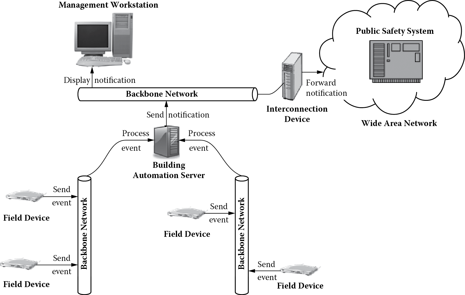
Figure 6.1 gives an operational view of the building automation system. The overall goal of the building automation system is to monitor the locations within the buildings (using field devices) for normal building operations such as HVAC (heating, ventilation, air conditioning), lighting, safety, and security. These devices periodically report back the conditions, and the facility managers can monitor these conditions on their management workstations. Conditions that may threaten the safety and security of the building residents are raised as alarms so that prompt action can be taken. Figure 6.2 shows one such operational scenario.
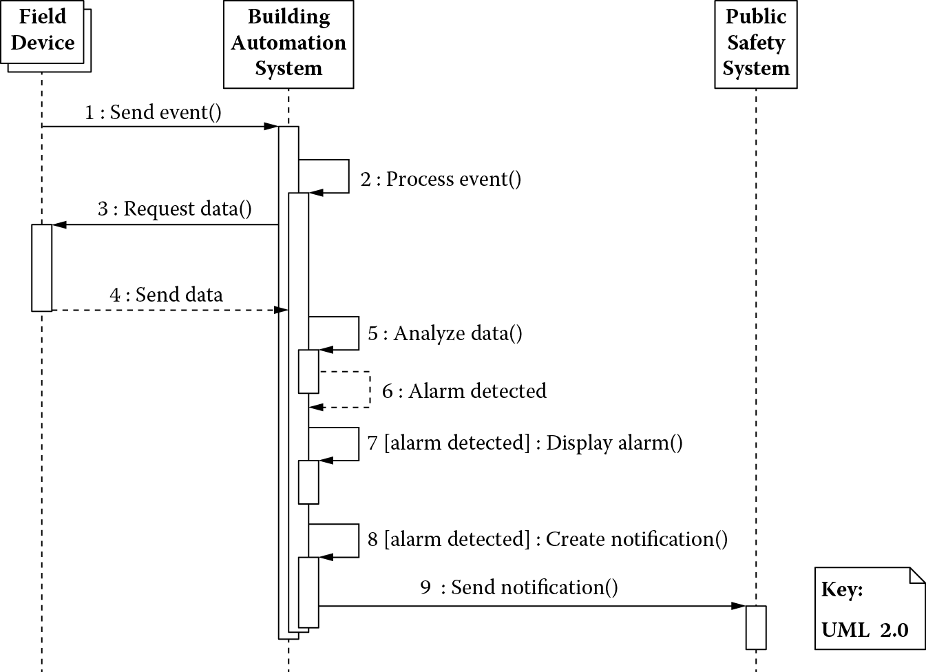
As shown in Figure 6.2, many field devices concurrently transmit events to the building automation system. The building automation system processes these events, requesting additional data from these devices to determine if there is a safety hazard. If so, an alarm is generated; it is displayed on a management workstation, and a notification is sent to the public safety system.
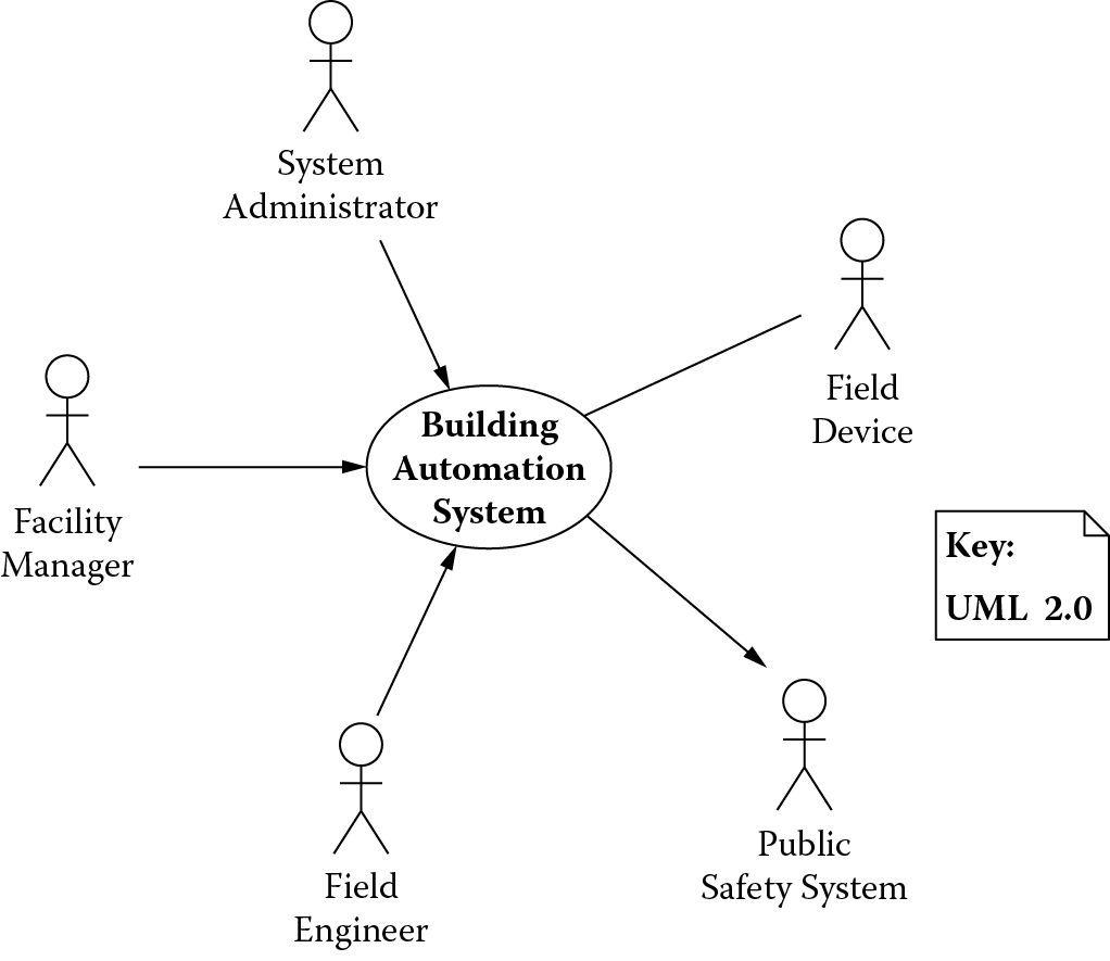
In addition to facilities managers monitoring the building for normal operations, field engineers intend to manage the field devices and dynamically reconfigure them, and the system administrators intend to manage the users of the building automation system. The overall context of the building automation system is shown in Figure 6.3.
6.5.2.3 Section 2.3: Functions
The building automation system must provide certain critical features to support the engineering objectives shown in Table 6.1. For instance, integration implies the features of existing applications to be integrated must be supported in the new system. This may require innovative ways of displaying information in the user interface and providing fine-grained access control on who is allowed to interact with what part of the system.
Supporting international languages implies personalization capabilities. Regulatory policies for safety-critical parts of the system would require alarm-handling capabilities for situations that could cause loss of life. Supporting hardware devices from different manufacturers would require dynamic configuration capabilities.
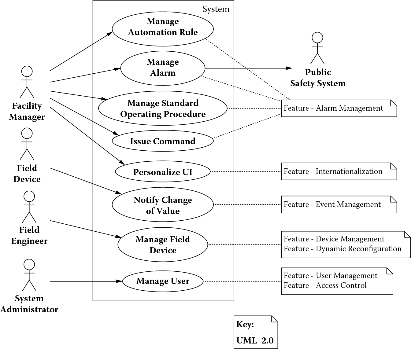
Figure 6.4 shows the refinement of these features into specific use cases based on how the external actors shown in the context diagram in Figure 6.3 intend to use the system.
The use cases imply the following functional responsibilities that the building automation system must fulfill:
- Send commands to a field device
- Receive events from a field device
- Perform semantic translation for field device data
- Configure a field device
- Route data to a field device
- Evaluate and execute automation rules
- Send automation commands
- Generate alarm notifications
- Display device data
- Capture/relay user commands
- Display alarm notifications
- Edit/create automation rules
- Retrieve data from a field device
- Store field device configuration
- Propagate change-of-value notifications
- Authenticate and authorize users
- Persist automation rules, user preferences, alarms
6.5.2.4 Section 2.4: Quality Attribute Requirements
Critical qualities the building automation system must exhibit to support the engineering objectives are shown in Table 6.2. Each quality attribute is elaborated with a concrete scenario that can be used to assess the suitability of the final architecture.
Quality Attributes and Scenarios Derived from Engineering Objectives
|
Engineering Objective |
Quality Attribute |
Quality Attribute Scenario |
|
Support hardware devices from many different manufacturers |
Modifiability |
A field engineer is able to integrate a new field device into the system at runtime and the system continues to operate with no downtime or side effects. |
|
Support conversions of nonstandard units used by the different devices |
Modifiability |
A system administrator configures the system at runtime to handle the units from a newly plugged-in field device and the system continues to operate with no downtime or side effects. |
|
Support international languages |
Modifiability |
A developer is able to package a version of the system with new language support in 80 person-hours. |
|
Comply with regulations requiring life-critical systems to operate within specific latency constraints |
Performance |
A life-critical alarm should be reported to the concerned users within 3 s of the occurrence of the event that generated the alarm. |
6.5.2.5 Section 2.5: Constraints
Table 6.3 enumerates additional factors that have to be considered as they may constrain how the architecture for the building automation system is designed.
Constraints
|
Category |
Factor |
Description |
|
Organization |
Expertise |
The development organization has a strong background in development on the Microsoft platform. |
|
Technology |
Cost |
The system must reuse the company’s existing rules engine. |
|
Product |
Variability |
The system must handle a wide range of disparate field devices and configurations, ranging from 500 to 50,000 such devices, at customer sites. |
6.5.2.6 Section 2.6: Architectural Drivers
A prioritized list of architectural drivers for the system is shown in Table 6.4 along with the sources (quality attribute scenarios, product features, constraints) from which they were derived. The priorities are shown as tuples derived by soliciting input from both the business and the technical stakeholders. The business stakeholders prioritized drivers based on their business value (H, high, implies that a system lacking that capability will not sell; M, medium, implies that a system lacking that capability will not be competitive; L, low, implies it is something nice to have), whereas the technical stakeholders did so based on how difficult it would be to achieve a given scenario during the system design (H, high, implies a driver that has a systemwide impact; M, medium, implies a driver that has an impact on a significant part of the system; L, low, implies a driver whose impact is fairly local and therefore not architecturally significant). This results in nine different combinations in the following order of precedence: HH, HM, HL, MH, MM, ML, LH, LM, and LL.
Architectural Drivers
|
No. |
Architectural Driver |
Source |
Priority |
|
1 |
Support for adding new field device |
|
(H, H) |
|
2 |
International language support |
|
(M, M) |
|
3 |
Nonstandard unit support |
|
(H, M) |
|
4 |
Latency of alarm propagation |
|
(H, H) |
|
5 |
Load conditions |
|
(H, H) |
Note: H, high; M, medium.
Architectural drivers 1 through 5 relate to the quality attribute scenarios enumerated in Table 6.2. In addition, architectural drivers 1 and 3 also correspond to the device management and dynamic reconfiguration, 2 to the internationalization and localization, and 4 to event management and alarm management product features shown in Figure 6.4. Also, architectural drivers 1, 3, and 5 address the product variability constraint from Table 6.3.
6.5.3 Section 3: View Template
A view’s primary function is to show the structure that it represents. Its documentation, therefore, consists of the following:
- Primary presentation: shows the elements in a structure and the relationships among them.
- Element catalog: details at least those elements and relations depicted in the primary presentation; these details include the interfaces of the elements and how these elements behave at runtime.
- Architecture background: explains the design rationale, analysis results, and assumptions.
All views contained in Section 4 use this standard template.
6.5.4 Section 4: Views
The purpose of each view is to address specific stakeholder concerns as discussed previously.
6.5.4.1 Section 4.1: Module View
The module view serves as the basis for making decisions on how to structure the system into cohesive units of implementation such that
- The impact of an anticipated change is localized;
- Making this change does not ripple to other parts of the system that depend on the element being changed;
- When desired, the change can be made while the system is in operation without any downtime or side effect.
6.5.4.1.1 Section 4.1.1: Primary Presentation
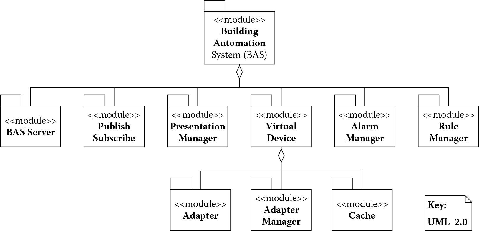
Figure 6.5 shows the major modules that make up the building automation system.
6.5.4.1.2 Section 4.1.2: Element Catalog (Modules)
Table 6.5 lists the responsibilities of the major modules in the building automation system.
Major Modules and Their Responsibilities
|
Module |
Responsibilities |
|
|
1 |
Adapter |
|
|
2 |
Adapter manager |
|
|
3 |
Alarm manager |
|
|
4 |
BAS server |
|
|
5 |
Cache |
|
|
6 |
Presentation manager |
|
|
7 |
Publish-subscribe |
|
|
8 |
Rule manager |
|
6.5.4.1.3 Section 4.1.3: Architecture Background
Figure 6.6 highlights the design decisions that were made to improve the modifiability of the building automation system.
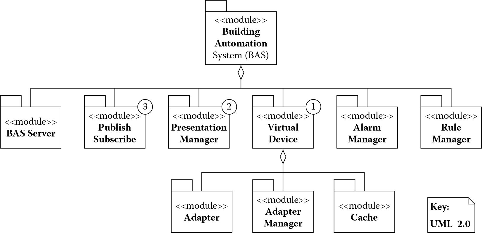
The design decisions, marked in Figure 6.6 and cross-referenced in the material that follows, achieve the following:
- Decision 1 (virtual device): Hides communication with the field devices
- Decision 2 (presentation manager): Hides details of user interaction, their language, and locale preferences
- Decision 3 (publish-subscribe): Decouples data providers from data consumers, providing a generalized interface for reliable event delivery
Together, these decisions satisfy architecture drivers 1–3 (see Table 6.4).
6.5.4.2 Section 4.2: Component-and-Connector View
The component-and-connector view serves as the basis for making decisions on how to structure the system into runtime units of interaction such that
- Resources manage their demand efficiently, minimizing latency and maximizing throughput.
6.5.4.2.1 Section 4.2.1: Primary Presentation
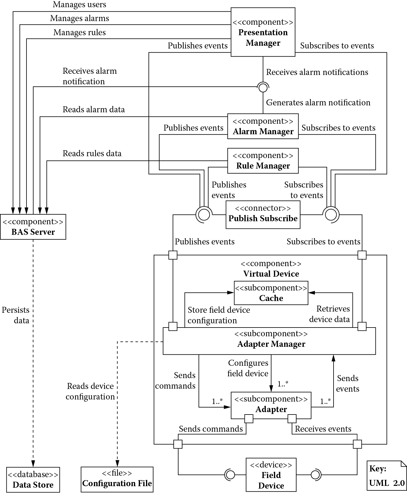
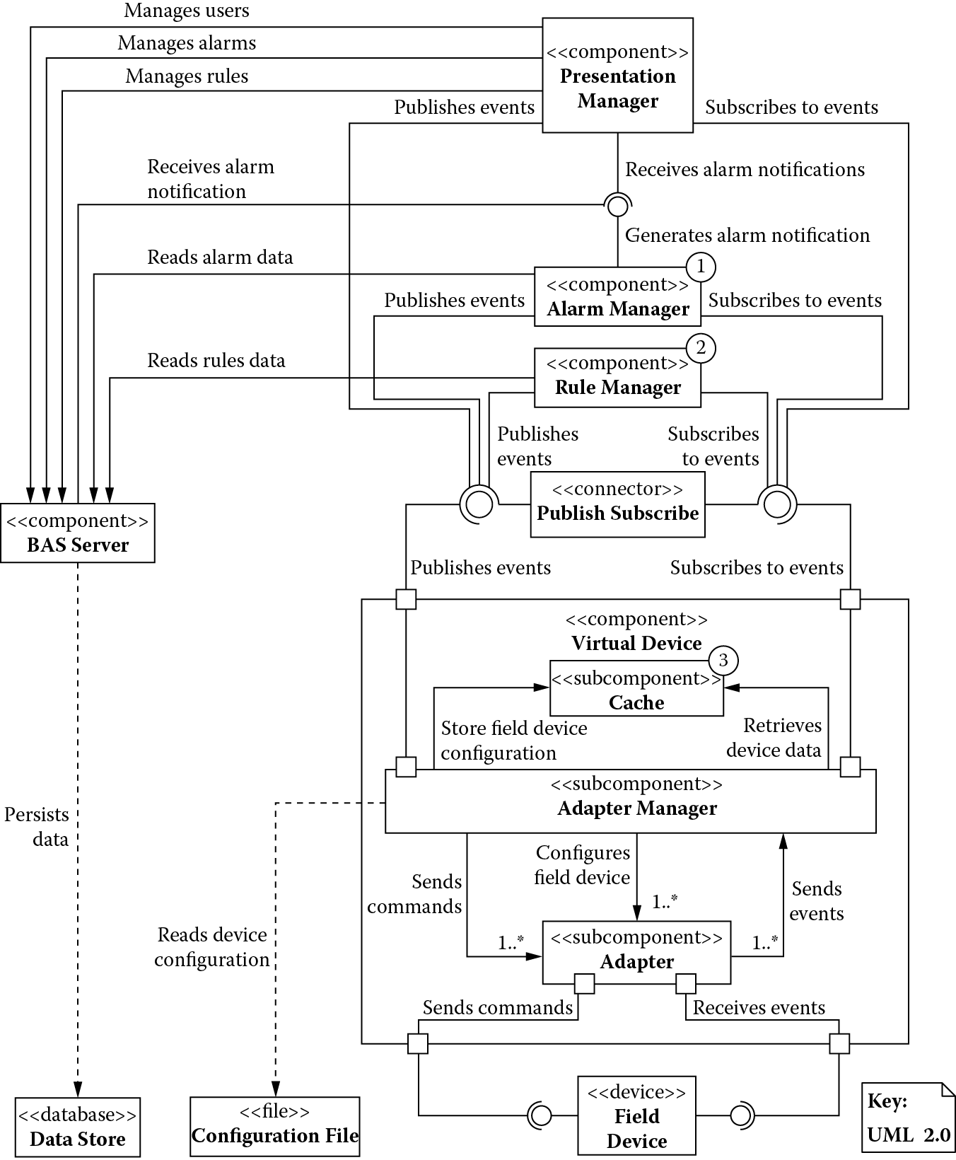
Figure 6.7 shows the major components that make up the building automation system.
6.5.4.2.2 Section 4.2.2: Element Catalog (Components)
Table 6.6 lists the responsibilities of the major components in the building automation system.
Major Components and Their Responsibilities
|
Component |
Responsibilities |
|
Alarm manager |
|
|
BAS server |
|
|
Presentation manager |
|
|
Rule manager |
|
|
Virtual device |
|
6.5.4.2.3 Section 4.2.3: Element Catalog (Connectors)
Table 6.7 lists the responsibility of the major connector in the building automation system.
6.5.4.2.4 Section 4.2.4: Element Catalog (Behavior)
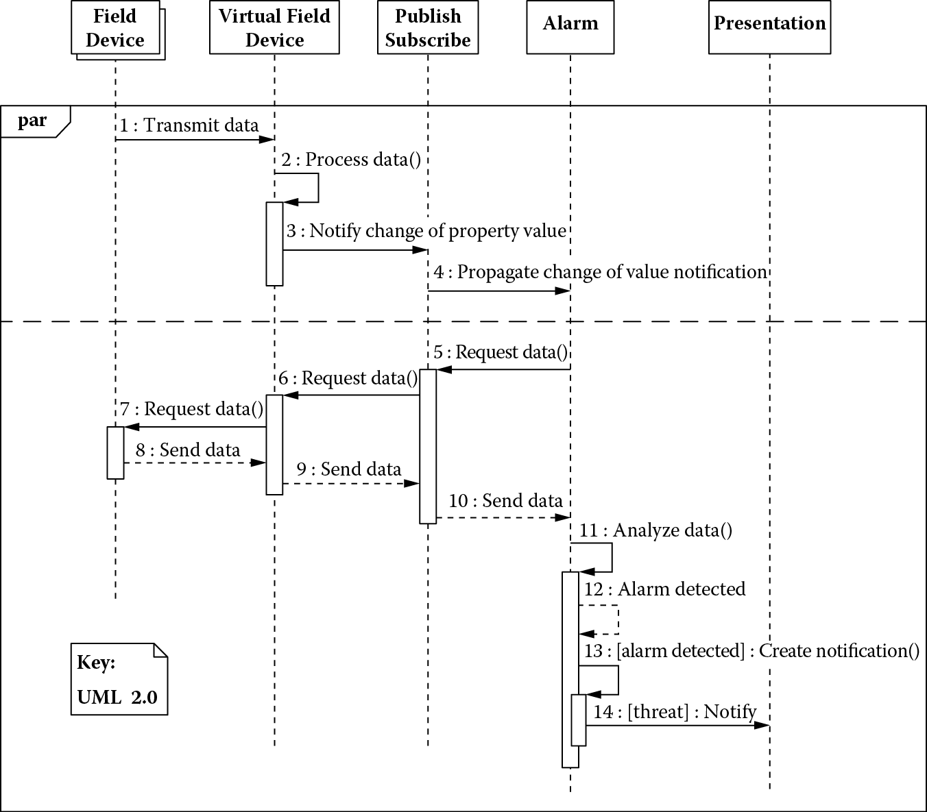
Figure 6.8 shows a process view that captures how components behave at runtime. Many field devices concurrently transmit data to the virtual field device. The virtual field device processes the raw data, which are then made available for analysis to the alarm subsystem via the publish-subscribe connector. When alarms are detected, the alarm manager notifies the presentation component, which displays the alarm on a facilities manager’s workstation.
6.5.4.2.5 Section 4.2.5: Architecture Background
Figure 6.9 highlights the design decisions that were made to improve the performance of the building automation system. The design decisions, marked in the figure and cross-referenced here, achieve the following:
- Decision 1 (alarm manager): Minimizes alarm propagation latency through concurrent processing of alarm events and concurrent evaluation of alarm rules
- Decision 2 (rule manager): Reduces load by offloading from the system, processing of field device events and their related rules
- Decision 3 (cache): Reduces latency of retrieving property values from a field device
Together, these decisions satisfy architecture drivers 4 and 5 (see Table 6.4).
6.5.4.2.5.1 Section 4.2.5.1: Performance Model—We have created analytic models (along with prototypes/simulations) to have further confidence in the design decisions we have made. Figure 6.8 shows message flow across key hardware and software elements; in the event that data from the field devices begin to indicate the possibility of an alarm, the facilities managers need to know about this possibility within 3 s of its occurrence (architecture driver 4 in Table 6.4).
Table 6.8 shows total computer resource requirements for this model. We have made a simplifying assumption that all components are deployed and running together on the same machine; hence, the time taken by the publish-subscribe to propagate data received from the virtual device to the alarm subsystem is negligible. It is therefore ignored in subsequent calculations.
Computer Resource Requirements for Alarm Processing
|
Processing Step |
CPU Instructions (K) |
Physical I/O |
Network Messages |
|
Transmit data (field device) |
30 |
6 |
3 |
|
Process data (virtual field device) |
60 |
8 |
4 |
|
Analyze data (alarm) |
130 |
6 |
3 |
|
Total |
220 |
20 |
10 |
Note: I/O, input/output.
If a central processing unit (CPU) takes 0.00001 s to execute 1,000 instructions, a disk takes 0.02 s for every physical input/output (I/O), and network message takes 0.01 s processing time, the best-case elapsed time for the alarm detection scenario is
(220 × 0.00001) + (20 × 0.02) + (10 × 0.01) = 0.50220 s
This is well under our 3-s requirement, ignoring network delays and processing overhead that may result when components are deployed on different machines.
6.5.4.3 Section 4.3: Deployment View
The deployment view serves as the basis for making decisions on how to structure the system into runtime units of interaction such that
- Components can be colocated and deployed together to reduce interprocess communication overhead.
- Components can be deployed independently and resources can be added seamlessly for scaling the system to meet its resource demand.
6.5.4.3.1 Section 4.3.1: Primary Presentation
Figure 6.10 shows the deployment and interactions of the major components that make up the building automation system.
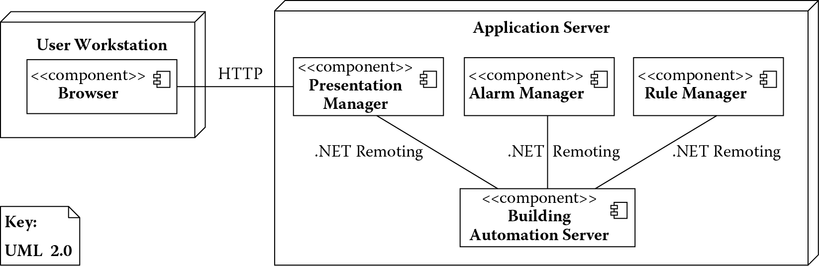
6.5.4.3.2 Section 4.3.2: Element Catalog
Table 6.9 lists the responsibilities of the major components deployed in the building automation system.
Major Deployment Units and Their Responsibilities
|
Element |
Description |
|
Alarm manager |
The alarm manager runs as a separate process and will communicate, using .NET remoting, with the various components for managing the life cycle of an alarm. |
|
BAS server |
Deployed as a .NET executable in a separate process, this is the main component that controls user access to the building automation system and manages event and data flow to/from the field devices and other components using .NET remoting. |
|
Browser |
There will be some code in the form of Javascript in the browser used for interaction with the presentation manager for displaying alarms and status of different field devices on the user workstation. |
|
Presentation manager |
This component contains one or more .NET assemblies for the web page and other client-side resources that will be executed as a dedicated ASP .NET process and will communicate with other components by means of .NET remoting. |
|
Rule manager |
The rule manager runs as a separate process and communicates, using .NET remoting, with the various components when evaluating rules and commanding field devices. |
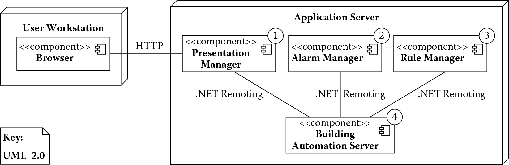
6.5.4.3.3 Section 4.3.3: Architecture Background
Figure 6.11 highlights the design decisions that were made to improve the scalability of the building automation system. The design decisions (marked 1 through 4) in the figure provide a great deal of flexibility in how components are deployed. They allow the marked components to be deployed independently as a .NET assembly and allocated their own resources, thus distributing system load and improving scalability. By the same token, some of them could be colocated on a single machine if desired and execute as a separate process or the same process to reduce communication overhead caused by crossing machine and network boundaries. Together, these decisions satisfy performance-related architecture driver 5 (see Table 6.4).
6.5.5 Section 5: Mapping between Views
Mapping between views draws comparisons between different views of the system, highlighting areas that are common to these views. Table 6.10 shows how modules map to the different components of the building automation systems and the relationship among them. Table 6.11 shows how components in the component-and-connector view map to those deployed at runtime and the relationship among them.
6.5.6 Section 6: Rationale
This section explains how the overall architecture is a solution to its requirements, why it was chosen, and the implications in changing it:
Business context: Our company manufactures devices for the building automation domain and software applications that manage a network of these devices. With the hardware being commoditized, its profit margins have been shrinking. The internal development costs for the software applications that manage different devices have also been rising. To sustain their business long term, the company has decided to create a new integrated building automation system. Taking this approach would allow the company to reduce internal development costs—several existing applications will be replaced with the new system. The company could also achieve market expansion by entering new and emerging geographic markets and opening new sales channel in the form of VARs.
Key features:
- Dynamic reconfiguration and field device management: Support hardware devices from different manufacturers
- Alarm management: Complies with regulations requiring covering life-critical systems, such as fire alarms, to operate within specific latency constraints
- User management, access control, and event management: Integrate existing applications into a single unified software
6.6 Conclusions
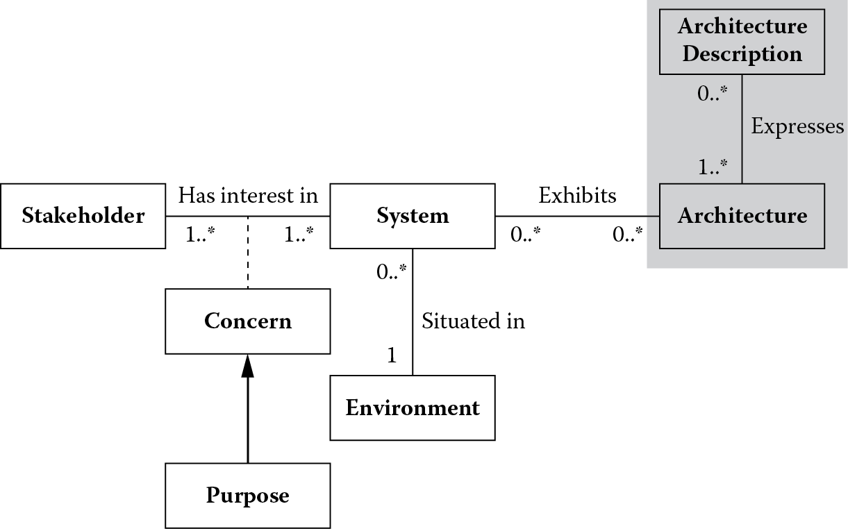
This chapter explored the shaded portion of International Organization for Standardization/International Electrotechnical Commission (ISO/IEC) 42010 conceptual framework for system and software architecture shown in Figure 6.12. We demonstrated the use of the views-and-beyond approach for documenting the architecture and capturing its design rationale. Stakeholders have diverse concerns, and organizing the documentation as a set of views, in which each view addresses a specific set of concerns, helps them navigate the architecture documentation in a focused way to examine if their design concerns have been satisfied. The documentation example provided was intentionally kept brief, with emphasis placed on concepts learned in previous chapters. Those interested can explore the details of this approach in the work of Clements et al. (2010). Dickerson and Marvis (2009) discussed other architecture documentation frameworks (Department of Defense Architecture Framework [DoDAF] and Ministry of Defense Architecture Framework [MoDAF]) that are widely used in the defense community.
6.7 Questions
- In a previous chapter, you created the architecture of the patient monitoring system. Create an architecture description document similar to the one discussed in this chapter for the patient monitoring system.
- In a previous chapter, you modified the architecture of the building automation system to improve the availability of the virtual devices. Add another view to the architecture description document of the building automation system that captures your enhancements.
References
P. Clements, F. Bachmann, L. Bass, et al., Documenting Software Architecture: Views and Beyond, second edition. Upper Saddle River, NJ: Addison-Wesley, 2010.
C. Dickerson and D. Marvis, Architecture and Principles of Systems Engineering. Boca Raton, FL: CRC Press/Auerbach, 2009.
ISO/IEC/IEEE Systems and Software engineering—Architecture description, ISO/IEC/IEEE 42010:2011(E) (Revision of ISO/IEC 42010:2007 and IEEE Std 1471-2000), pp. 1–46, 2011.