
CHAPTER 7 Software Dependability
Learning objectives of this chapter are to understand:
• The application of fault avoidance and fault elimination in the software lifecycle.
• The techniques available for avoiding faults in software.
• The techniques available for eliminating faults in software.
• Which phases of the software lifecycle tend to introduce the most faults.
• The best way to approach software dependability.
• Formal methods and why are they important.
• How an engineer can be reasonably confident that the various classes of faults that might occur in a system have been dealt with.
7.1 Faults and the Software Lifecycle
Software has been a causal factor in many failures of systems that required high levels of dependability. Knowing that, we must be aware of the potential that software has to affect dependability, and we must apply the right techniques when building software. The right techniques are not in one or even a small number of areas. All of the activities that we undertake when building software might be opportunities for defects to enter software and remain there.
There is no “perfect” way to develop dependable software that can be used on every project. Different projects have different goals and different stakeholders, and so the process used has to be tailored to the specific circumstances of a particular project. Many techniques can facilitate software dependability, however, and so it is important to be aware of them.
This book and therefore this chapter is not about software engineering in general, and so this chapter does not discuss complete and detailed software development processes and techniques. Rather, in this chapter Section 7.2, Section 7.3, and Section 7.6 summarize three important special software topics: (a) formal methods, (b) model checking, and (c) model-based development. Elements of these three topics are then part of general discussions of software fault avoidance in Section 7.8 and software fault elimination in Section 7.9. Managing software fault avoidance and fault elimination is discussed in Section 7.10, and common misconceptions about techniques for fault avoidance and elimination in software development are reviewed in Section 7.11. In the following three chapters, specific topics in fault avoidance and elimination are investigated in depth.

FIGURE 7.1 The general form of the code responsible for the failure of the AT&T long distance telephone system in January 1990.
If achieving the necessary level of software assurance by fault avoidance and fault elimination is not possible, then our next goal is to tolerate faults. Software fault tolerance is covered in depth in Chapter 11.
Software fault forecasting is a specialized topic that involves the development and use of detailed probabilistic models of software dependability. This material is outside the scope of this book.
7.1.1 Software and Its Fragility
A Significant Failure
Software cannot be seen, felt, or touched, yet it is responsible for much of the functionality in critical systems and also for many failures. Sometimes, a single defective line of code in a software system is all that it takes to cause that system to fail. An example of this situation arose on January 15, 1990, when large sections of the AT&T long distance network failed.
The failure was determined later to have been caused by one line of a program written in C [102]. The general form of the code is shown in Figure 7.1. The fault in this code was the use of the break statement within the if statement. The semantics of a break statement are to terminate the enclosing switch or iteration statement. The programmer thought that the break statement was the equivalent of a branch out of the if statement, whereas, in fact, the enclosing case statement of the switch was terminated.
Generally, a single line of code is not expected to have such power, and that is why software failures are hard to predict and often hard to analyze. In a sense, the problem is akin to a large building collapsing when a single screw is removed from a door hinge on the fifth floor. Architects know that this will not happen to their buildings. Software engineers know that this might happen to their software.
Our concern with software, as with everything else, is to apply the fundamental principle of dependability, i.e., to capture the requirements correctly, to identify all of the faults to which the software is subject, and then to determine how to deal with all of those faults. Recall that software faults are always design faults, and so none of the specific techniques developed to deal with hardware degradation faults necessarily applies directly or with the same effect. Fortunately, however, the general concepts of fault avoidance, fault elimination, fault tolerance, and fault forecasting can be applied.
Logical Complexity
Although this book is about software, the difficulty we face is actually not software1. The real difficulty is logical complexity, and that complexity arises in both software and hardware. Logical complexity is sometimes expressed as bits in memory (software) and sometimes as patterns in silicon (hardware). The fragility of software arises from the associated complexity. But hardware is complex too, and hardware can be fragile in the same sense. Thus, the problems with design faults in software can and do arise in hardware.
The reason we use software is because we are trying to encode logical complexity, and software is a convenient means of doing so. The problem then is not that the entities with which we are concerned are software. Rather, the entities are complex, and we choose to implement them in software. In dealing with computer systems, keep in mind that both software and hardware are subject to design faults. The focus in this book is software, because software is often the choice we make to implement the complex entities that we need.
7.1.2 Dealing with Software Faults
In principle, systems can be built without design faults, and so, again in principle, we can build software without faults. To do so means relying upon fault avoidance and fault elimination, but in practice this is extremely difficult to do except in special cases. Establishing freedom from faults by analytic means is rarely possible, because much of software development remains informal and formal techniques cannot cope well with huge complexity.
Does this mean that we have to turn to fault tolerance and fault forecasting for design faults in general and software faults in particular? These two approaches play a major role in dealing with degradation faults in hardware. However, as we saw in Section 6.4, their application to hardware degradation faults relies in large measure on two powerful properties:
• For degradation faults, failures of independent hardware units tend to be statistically independent.
• For degradation faults, the probability of failure per unit time for hardware units is described quite accurately by the bathtub curve (see Section 3.5.1).
Unfortunately, software components do not display either of these characteristics, and the application of fault tolerance and fault forecasting to software is much more difficult as a result. Far more reliance, therefore, has to be placed on fault avoidance and fault elimination.
7.1.3 The Software Lifecycle
Faults can be introduced during virtually any stage of software development. Specifications can be wrong, designs can be wrong, and so on. To the extent possible, defects should be avoided at every stage and those introduced should be eliminated at the stage in which they were introduced. Both fault avoidance and fault elimination techniques can and should be applied to all the artifacts as they are developed.

FIGURE 7.2 The classic software lifecycle and the introduction of faults.
The classic software lifecycle is shown in Figure 7.2. This complete lifecycle provides a lot of insight into our task as software engineers when developing systems for which dependability is important. All the primary artifacts that we build are shown, and the lifecycle shows us, at a high level, where faults might be introduced and where we can try to deal with them.
7.1.4 Verification and Validation
Two terms that arise frequently in software dependability are verification and validation. For our purposes, we will use these definitions:
Validation. Developing the necessary assurance that the documented specification solves the problem stated in the abstract requirements (see Section 2.5), i.e., the system to be developed will solve the problem posed by the user.
Verification. Showing that one representation of software is a refinement of another, usually that the executable software is a correct implementation of the documented specification.
Informally, validation can be thought of as developers answering the question: “Did we build the right thing?”. Verification is applied most commonly to show that an implementation implements a specification correctly, and so verification can be thought of as developers answering the question: “Did we build the thing right?”. The basic relationships involved in validation and verification are illustrated in Figure 7.3.
Clearly the answer to either of these questions could be “no”, in which case we would expect system failures in operation. The system might do one of two things:

FIGURE 7.3 Validation and verification in software development.
• Something that the user did not want but do so correctly (erroneous specification, correct implementation).
• Something that the user wanted but do so incorrectly (correct specification, erroneous implementation).
The first statement of how software will solve the user’s problem is the specification, and so validation is concerned with whether the stated specification provides the necessary functionality. Validation, therefore, is precisely what is needed to deal with the first issue raised by the Fundamental Principle of Dependability (Section 3.9) for software.
Verification is concerned with the various representations that are created during software development. Apart from the common use of verification in showing that a high-level-language implementation provides the functionality that is defined in a specification, other uses of verification include implementation to design and design to specification. Verification, therefore, is precisely what is needed to deal with the second issue raised by the Principle of Dependability for software.
Verification and validation are at the heart of the process of developing software for applications that require high dependability. All the other elements of the software lifecycle are concerned with fault avoidance or fault elimination. Verification and validation are concerned with showing that the Principle of Dependability has been satisfied.
7.2 Formal Techniques
7.2.1 Analysis in Software Engineering
One of the best hopes that we have for technological support in building dependable software is the use of formal methods. Formal methods employ mathematical rigor to help establish a variety of properties about software. The reason they are so powerful is that they can help us establish properties such as freedom from certain classes of faults. Thus, they are precisely what we need for software fault avoidance and elimination. Using formal methods is not a panacea, but their use does offer us a lot of value if applied carefully. Formal methods must always be supplemented with various informal techniques such as prototyping, inspection, proper documentation, and careful management.
Developing software is a major intellectual challenge, and engineers need as much help as they can get to tackle the challenge. In other disciplines, engineers rely to a large extent on mathematics to model systems and thereby to predict their dependability characteristics. In structural engineering, for example, finite-element analysis allows various aspects of the strength of structures to be predicted. The predictions are usually so accurate that structural failures resulting from design flaws (as opposed to things like faulty construction or poor maintenance) are rare. Similarly, aerodynamicists rely on the various forms of the Navier-Stokes equation to predict the flow of fluids (typically air) over surfaces. From the details of the flow, lift and drag can be predicted, from which many details of the flight characteristics of an airplane can be determined.
An important characteristic of the analysis undertaken in both structural analysis and fluid mechanics is continuity, i.e., these analyses rely upon continuous mathematics. This characteristic means that the analysis can call upon the entire body of classical mathematics, including the calculus. A second consequence of continuity is the ability to extrapolate to circumstances beyond experience by applying the available continuous functions. This second consequence enables prediction by analysis of the effects of, for example, structural changes. A structure can be made stronger by adding additional structural elements and analysis will predict the strength. Doubt in the adequacy of structural strength can thus be dealt with by making structures thicker or by duplicating them.
There are relatively few analysis techniques available in software engineering and even fewer that are routinely applied. In large measure, this lack is the result of software being discrete, i.e., not continuous. Software engineers rely upon natural language documentation and testing to a large extent in developing products. This approach produces products that work most of the time, but the type of prediction about performance that is common in other fields of engineering is not available. Software engineers are not able to predict that an aircraft’s software-based autopilot will work as desired without testing it. By contrast, structural engineers can predict accurately that an aircraft’s wings will not break off in flight and aerodynamicists can predict that the aircraft will fly, both without any testing. The contrast, illustrated in Figure 7.4, is between using testing to establish a conclusion (software engineering) and testing to confirm a conclusion (most other branches of engineering).

FIGURE 7.4 Analysis vs. testing in software and other branches of engineering.
A formal method is an application of mathematics, usually discrete mathematics, in software engineering. As such, a formal method provides the software engineer with a basis for analysis much like the capability that is common in other fields of engineering. The goals of formal methods are:
• To provide formal languages that replace much of the use of natural language in artifacts such as requirements, specifications, and designs.
• To allow properties of software to be determined without executing the software.
Rather than trying to establish those properties by executing large numbers of test cases, executing a relatively small number of test cases should work to confirm the results of analysis.
The uses of formal methods are summarized in Figure 7.5. The notations used are formal languages, and the artifacts produced are amenable to analysis because of the formal languages. Some analysis is limited to a single artifact, in which case the results of the analysis allow insights about that single artifact. Other analysis involves more than one artifact, in which case the analysis can be considerably more powerful. An example of the latter is the concept of formal verification. The implementation and specification are analyzed together and a proof established that the implementation is a refinement of the specification.
Some engineers have a negative impression of formal methods. In part, these impressions are based upon myths that have circulated, and two papers have been written to counter some of the common myths [54, 20]. The myths discussed and dispelled in these papers are:

FIGURE 7.5 Formal languages and analysis in formal methods. Formal languages are used for both specification and implementation, and analysis can be performed on either or both.
1. “Formal methods can guarantee that software is perfect.”
2. “Formal methods are all about program proving.”
3. “Formal methods are only useful for safety-critical systems.”
4. “Formal methods require highly trained mathematicians.”
5. “Formal methods increase the cost of development.”
6. “Formal methods are unacceptable to users.”
7. “Formal methods are not used on real, large-scale software.”
8. “Formal methods delay the development process.”
9. “Formal methods lack tools.”
10. “Formal methods replace traditional engineering design methods.”
11. “Formal methods only apply to software.”
12. “Formal methods are unnecessary.”
13. “Formal methods are not supported.”
14. “Formal-methods people always use formal methods.”
None of these statements is true. Formal methods are neither a panacea that solves all problems nor a curiosity that provides no value. Formal methods are an important engineering technology.
7.2.2 Formal Specification
There are a variety of properties of specifications that are important: accuracy, completeness, consistency, freedom from ambiguity, and ease of change. Creating a specification that has these properties purely in natural language has proved to be difficult. Certainly, natural language has been used satisfactorily for specification, but the difficulties that arise typically have led researchers to seek better notations.
The result of the search has been the development of formal languages designed especially for software specification. All of the languages have mathematical semantics, i.e., the meaning of each of the various language elements is defined in terms of mathematics, and many (but not all) use a mathematical syntax. Some example formal languages are: Z [134], B [1], VDM [74], PVS [136], RSML [86], and Statecharts [57]. We examine Z in Chapter 7.
7.2.3 Formal Verification
Formal verification brings the rigor of formal methods to the challenge of verification. The primary application of formal verification is to establish that an implementation implies a specification. Such a proof is called a proof of partial correctness. If the program in question is expected to terminate, then a proof of termination can be added to the proof that the implementation implies the specification to produce a proof of total correctness (see Figure 7.6).
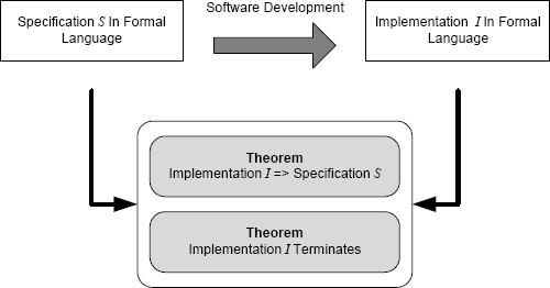
FIGURE 7.6 Proof of partial correctness and proof of termination provide proof of correctness.
7.2.4 The Terminology of Correctness
The use of the word “correctness” in formal verification is generally regarded as misleading. The problem is that people unfamiliar with the terminology will misinterpret the use of “correctness” in formal verification. Engineers in other fields, customers, regulators, or other stakeholders often assume that a program will do what they want if the program is “proven correct”. This is not the case, because the requirements, the specification, or the proof could be wrong. In that case, the intuitive notion of correctness is deceptive. A better way to describe this notion of proof is as a formal verification proof.
7.3 Verification by Model Checking
7.3.1 The Role of Model Checking
Model checking is an important technique that is quite different from the other formal methods that we have been discussing. At the heart of model checking is the idea that analysis can be carried out on a model of an artifact rather than the artifact itself, hence the name.
This idea applies immediately to software and with great value. The most common application to software is in concurrency. The statements in a program that affect the program’s concurrent behavior are largely independent of much of the rest of the program. For example, task creation and the synchronization of tasks do not depend on arithmetic computations except to the extent that the latter affect normal control flow. A model of the concurrent aspects of a program can omit many of the details of computation.

FIGURE 7.7 Analysis of a model and the relationship of the artifact to the model.
Concurrent software is difficult for humans to reason about, to test, and to analyze using formal verification. A good example of the difficulties is deadlock. The concept of a deadlock and the conditions necessary for one to happen are relatively easy to state. But to show that a given set of concurrent processes will not deadlock under any execution circumstances can be difficult unless the set of processes is designed explicitly to avoid deadlock.
Difficulties such as showing freedom from deadlock arise because of the non-determinism that is inherent in concurrent programs. Each time a concurrent program executes, there can be large differences in the events that occur and in the sequence of these events. Reasoning about such circumstances is difficult because of the vast number of event sequences, and a successful test execution means that only one possible event sequence has been tested. Thus concurrency, one of the major challenges that arises in software verification, is well suited to analysis by model checking.
7.3.2 Analyzing Models
The idea of analyzing a model of an artifact rather than the artifact itself is familiar in engineering. Electrical engineers determine the characteristics of a circuit based on a mathematical model of that circuit. Similarly, structural engineers base their analysis on models of the structures that they build. In both cases, the details of the underlying systems are complex and do not contribute to the goals of the analysis. For example, an electrical circuit contains stray capacitance and inductance that do not contribute to the direct-current calculations of the circuit and so a model that ignores them is perfectly satisfactory.

FIGURE 7.8 Using a model checker to analyze software.
Analyzing a model is illustrated in Figure 7.7 and means two things:
• The model is an abstraction of the artifact with much of the detail omitted. Only the aspects of the artifact that are relevant to the analysis are retained and so various forms of analysis become possible that would be impossible with the detail included.
• The analysis is carried out on a model, and the results of the analysis apply to the model. Provided the model is an accurate representation of the artifact, the results apply to the artifact. But the model must be accurate for the results to be useful.
An important example of the difficulty that can result from the use of models occurred in the field of civil engineering in the design of the suspended walkways in the Hyatt Regency hotel in Kansas City. Analysis of the forces on the walkway suspension system was possible because of the use of a model. The model was an accurate representation of the design, but the suspension system as built was different from the design and hence different from the model. The system as built was much weaker than the model predicted. The result was that the walkways collapsed on July 17, 1981, killing 114 people [105].
7.3.3 Using a Model Checker
The overall approach to using a model checker is shown in Figure 7.8. A model is prepared of the software system of interest in the modeling language that is supported by the model checker to be used. The model has to represent the necessary aspects of the program correctly and completely. Building models that have this property for large programs is difficult because of the amount of detail involved. As a result, various efforts have been undertaken to automate the model-building process by using tools that read the software and produce the model.
Next the properties that are desired of the software are formalized. This formalization is usually documented in a temporal logic known as Linear Temporal Logic, or LTL. LTL adds three new operators to predicate logic that allow the specification of the ordering of events. The three operators are:

The operators from propositional and predicate logic are included in LTL, thereby allowing expressions such as the following examples to be written:
• ![]()
This expression reads “Eventually p or eventually q.” In other words, no matter what state the computation is in, eventually either p or q will become true.
• ![]()
This expression reads “Always p and q.” In other words, no matter what state the computation is in, p and q will always be true.
In these examples, p and q are machine states of interest. For example, in a safety-critical system, p and q might be safety properties such as logic combinations that prevent hazards. The second expression states that these properties will always hold no matter what the system does. If states exist in which this condition is not true, then a model checker will locate such states and, for each such state, provide a list of the events that could lead to the state, i.e., a counter example.
For more details of model checking in general and the Spin system [133] in particular, see the text by Holzmann [63].
7.4 Correctness by Construction
Humans are fallible. Relying on human intellect almost unaided to build large software systems is clearly not a good idea. There is plenty of evidence showing that relying on human intellect rarely works perfectly. The fragility of software and the difficulties that arise with software fault tolerance and software fault forecasting lead us to the conclusion that we should emphasize software fault avoidance and software fault elimination. By doing so, we will be aiming to produce software that is to a large extent free of faults as a result of the way the software was developed.
To meet operational goals, traditional software development relies to a significant extent on testing and repair. Ideally, when software is written, that software should be correct and known to be correct from the outset. Many other branches of engineering work this way, and the embodiment of the idea in software engineering is a technique called correctness by construction [8].
Correctness by construction is a comprehensive approach to software development that embodies the ideas of fault avoidance and fault elimination that are pervasive in this book. The goal of correctness by construction is to know that the implementation is correct as a result of the way that the implementation was built. This goal is challenging, but if the goal could be met, software engineering would be a much more effective discipline.
Correctness by construction does not rely on extensive testing, but that change in emphasis does not mean that the software is not tested. Correctness by construction means that elaborate test activities are not required to find the faults in the software. This situation is highly desirable for systems where dependability is the goal. Testing can then take its proper place as a different means of gaining confidence that the software contains relatively few faults. Correctness by construction has been pioneered by several authors, including Sutton and Carré [137], Hall and Chapman [55], and Amey [8].
The use of the word “correctness” in the phrase proof of correctness was discussed in Section 7.2.4, and now the word has arisen again. The idea of correctness by construction is to develop each of the necessary artifacts in a manner that ensures critical properties as a result of the development method. Proof might be used, but there is no mention of proof in the name and no implication that might mislead other engineers.
7.5 Approaches to Correctness by Construction
There are three different approaches to correctness by construction of an implementation, as shown in Figure 7.9. The three approaches are: synthesis, refinement, and analysis:
Synthesis. In construction of software using synthesis, the implementation in a high-level language is actually built automatically by an application generator. The application generator reads a formal specification and generates the application software automatically. In some application generators, the synthesis process is guided by humans, and in others synthesis is completely automatic. Many application generators are available, including Mathworks Simulink, discussed in Section 7.6. When using Simulink, the input diagram is a formal specification and the code is generated mechanically.
Implementation correctness by construction is obtained using synthesis because the implementation (software) is written by a machine. Provided the synthesis mechanism is correct, we can be sure that the software implements the specification. The synthesis mechanism is a large program in its own right, and so assuming that synthesis does not introduce defects is a big assumption. The assumption is reasonable, however, because the synthesis mechanism will be used across many projects and by large numbers of engineers. Expending significant resources on this one artifact is likely to be worthwhile.
Refinement. In construction of software using refinement, software is built by developing a series of transformations from the high-level, abstract specification to a concrete implementation, usually in a high-level language. The key to fault avoidance is that transformations are selected and applied carefully, and proofs are constructed to show that, for each transformation that is applied, the properties of the input are maintained by the output. The transformations and proofs are usually developed by hand with extensive mechanical help. The transformations can be applied by sophisticated editors after being selected, and the proofs can either be generated mechanically or checked mechanically.
Refinement has been demonstrated with several formal-specification languages. The most extensive use of the approach has been with the B method. B includes a comprehensive treatment of refinement and is supported by a detailed textbook [1] and high quality tools [28]. The B method is discussed in Section 7.7.
Implementation correctness by construction is obtained using refinement because, when the implementation is complete, a proof exists from the software back to the specification. Provided the proof is correct, the verification argument is complete.
Analysis. In construction of software using analysis, the software is built by developing a series of program increments using a fairly conventional manual development approach. Design using procedural abstraction can be used to develop the necessary procedures and functions, data structures can be designed in a manner that provides the semantics for the application, and so on.
The key to the use of analysis is the availability of a mechanism to verify each of the increments that is applied during development. In principle, any verification technique could be used, including testing, but in practice reliance is placed on static analysis. The important argument in analysis is to build a program in steps where the increment added at each step is followed by verification. Confidence begins with the first iteration in which a small program is verified. As increments are added to build a progressively more complete program, so the verification grows. Provided each step adds only a relatively small increment to the software, then verification after each increment is developed can rely upon the verification of the program in the previous step as a starting point. Also, since only a relatively small change will have been made to the software, the incremental verification challenge is reasonable. The SPARK approach to correctness by construction using analysis is discussed in Section 9.5.
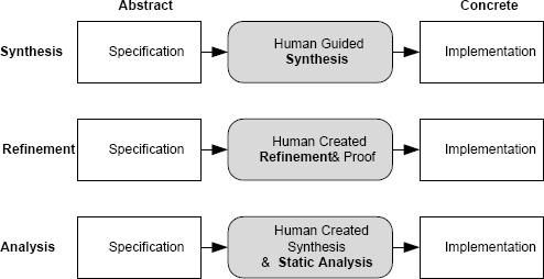
FIGURE 7.9 The three approaches to implementation correctness by construction.
To apply correctness by construction, the first step is to define the software development process to be used. Developers have to begin by seeking all of the places in which faults might arise during development. This information will allow the creation of a suitable development process for the system at hand. No single process is possible, because the circumstances of each system are different. A process for the development of custom software for an embedded system running on a high-performance modern microprocessor will be very different from the process used to develop an information system running on commodity hardware using commercial off-the-shelf (COTS) operating systems. A useful starting point for the development of a process to implement correctness by construction has been developed by Hall and Chapman [56].
A detailed example of correctness by construction in the development of a large distributed information system with high availability and security requirements is presented by Hall and Chapman [55].
Building software using correctness by construction seems as if it would increase development costs. Properly applied, it does not. In fact, there is strong evidence that the cost of development is reduced, often significantly, when compared to traditional methods. This cost reduction is not surprising when one considers that traditional methods rely on testing and repair to a large extent. Testing and repair are expensive activities, because they in turn rely heavily on expensive human effort. By eliminating much of this effort, correctness by construction can apply a small amount of additional human effort but do so differently and with greater effect. A particular example of the potential cost savings from correctness by construction has been reported by Amey [8].
7.6 Correctness by Construction — Synthesis
7.6.1 Generating Code from Formal Specifications
If the specification for a system is formal, then an implementation can, in principle, be created mechanically from that specification. In some cases, this idea is practical, and software can be created by machines rather than people. A general term that is sometimes used for this technique is software synthesis, and the tools used are sometimes referred to as application generators. One particular technique that has been developed is model-based development.
The concept is to develop a specification using a formal notation, and to have a tool translate that specification into an executable program, much as a compiler translates a high-level-language program into an executable program. This analogy points out the rather unfamiliar notion that what we call high-level-language programs are, in fact, specifications. A compiler writes the actual program, not the person who we usually call the programmer!
The specification languages used in model-based development are not those developed in the field of software engineering, such as Z and VDM. Rather, the languages are domain specific, i.e., each language is designed to be used by experts in a particular application domain rather than software engineers. Domain-specific languages are often graphical, and they permit domain experts to write formal software specifications in a notation with which they are familiar. The languages are essentially those developed within the application domain before computers came on the scene.
The term model-based development is most commonly associated with the field of control systems and related fields, such as signal and image processing. In model-based development of a control system, a controls engineer develops a specification of a control system using a standard graphic notation used by the controls discipline. This specification embodies the necessary control theory, but from the software perspective the specification is formal. This formal specification is translated into software in a high-level language using a synthesis tool.
Importantly, in this example of model-based development, the specification is developed by a controls engineer, not a software engineer. The notation used for the specification is a notation that comes from the field of control theory, not software engineering. And the actual software is synthesized by a powerful tool rather than being created by software engineers. Other than the development of the synthesis tools, software engineers do not play a central role in model-based development.
The way in which model-based development usually works is shown in Figure 7.10. Once an application expert has prepared a model of a system in a domain-specific language, the model can then be processed in two different ways — simulation and synthesis. Many support tools for domain-specific languages provide a simulation capability that permits the expert to “execute” the model and observe its behavior. Extra facilities are available to play the role of input data sources and output data displays. With this capability, the expert can examine the dynamic behavior of the model and determine (at least in part) whether the model describes the desired solution. This activity is a major component of validation in model-based development.

FIGURE 7.10 Application expert using domain-specific language to develop software.
Once the expert is satisfied with the model, synthesis is used to generate the implementation. The synthesis can often be tailored to specific targets and specific compiler options. Thus, the generated code can be created to meet the needs of complex target systems.
7.6.2 The Advantages of Model-Based Development
Many advantages are claimed for model-based development, including the following:
Less development effort. Much of the human effort that is needed in traditional software development is no longer needed. There is no software design or implementation, and verification is changed dramatically.
Closer to application, easier to validate. The specification is developed by an application expert in a notation with which he or she is familiar. Thus, validation is simpler and can be undertaken directly by the engineer who needs the system using a notation with which that engineer is familiar.
Independent of programming language. The source program created by the toolset is not determined by the skills and experience of programmers. Thus, any programming language could be used, and some synthesis systems actually support more than one. In fact, there is no technical need to generate source programs at all. A synthesis toolset could generate object programs directly. Most do not, however, because synthesis is used frequently in industries where software has to be approved by a certification agency. Most certification agencies undertake some of their responsibilities on software source programs.
No bugs from human development. In a sense, software synthesis is the best of all possible solutions to the problem of software dependability. Provided the tool that translates the specification to the executable program does so correctly, there is no possibility of faults being introduced in the translation. The requirement for accurate translation is not impossible to achieve. A translation tool would be widely used, and so exercising great care in the tool’s construction would be worthwhile.
Successful software synthesis would provide accurate translation and require the use of formal specifications. Software synthesis thereby changes the field of software engineering considerably. Developers can turn their attention to dealing primarily with the requirements and the specification. The bulk of software development as currently practiced — design, implementation, testing, and documentation — is no longer needed.
7.6.3 Examples of Model-Based Development Systems
Examples of software synthesis tools are actually quite common. Here are some examples:
Parser generators. Parser generators such as YACC and GNU Bison are programs that read a context-free grammar and produce a parser for the language defined by the grammar. The parser produced is usually in a high-level language. The context-free grammar is the formal specification in this case.
Spreadsheet formulas. The formulas that define the computation for the cells in a spreadsheet are entered by the user in an algebraic form and evaluated by the spreadsheet program when the data in the associated cells changes. In most spreadsheets, the target of translation is not a high-level language. Most spreadsheets translate the algebraic representation of the desired computation into a synthetic internal form that is interpreted for evaluation of the expression. In no case does the developer of a spreadsheet have to write traditional programs.
Visual Basic. Visual Basic provides the user with a palette of typical GUI graphics and a blank window. The user selects graphics from the palette that he or she wants to use in a GUI for a piece of software and drags them onto the blank window. The graphics can be changed and repositioned as desired. The graphics palette and the mechanics of placing them to define a GUI constitute a formal specification of the GUI.
Functionality for the graphic elements is added in Visual Basic using a highly stylized program structure. To create the actual software, Visual Basic uses a variety of techniques, but the implementation of the graphics uses a library of program modules. The modules for the graphics that are actually in use are assembled automatically into a composite whole for execution. Thus, Visual Basic is partly a synthesis system and partly a specialized procedural programming system.
An important characteristic of software synthesis is that successful synthesis systems operate in narrow application domains. Each synthesis system is able to generate software for very specific types of software only. YACC, for example, generates high performance parsers, but YACC is of little use if software is needed for a device driver. Narrow domains of applicability do not seriously detract from the power of software synthesis. The availability of different synthesis tools broadens applicability, and several might be used for a given application.
7.6.4 Mathworks Simulink®
An example of a widely used, commercial tool that supports model-based development is Mathworks Simulink [95]. Simulink is designed primarily for use in the field of control systems, although many features have been added as the tool has evolved, and Simulink is widely applicable.
The specification language for Simulink is graphic and operates much like Visual Basic by providing the user with a palette of graphic icons representing various basic computation building blocks. Simulink provides building blocks for the supported application domains, including blocks for signal differentiation, signal integration, time delays, a wide variety of mathematical functions, input/output device interfacing, logic functions, and so on. Models are built by selecting icons representing functional blocks from the palette and dragging the icon to a window where the model is being built.
Simulink supports both model simulation and software synthesis. Building blocks are available for use with simulation that support a variety of input signal sources and display forms.
An example of a simple Simulink model is shown in Figure 7.11. Figure 7.11(a) is the complete model showing an input icon and an output icon marked “Scope1”. The output icon is for display of the output of the model when it runs. Figure 7.11(b) is an expansion of the large central block (marked PID controller) in Figure 7.11(a). This shows Simulink’s capability for abstracting sub-systems and allowing their separate development.

FIGURE 7.11 Simple PID controller represented in Simulink. (a) is the overall model; (b) is the actual controller, shown as a single block in (a); and (c) shows a sample of the output as displayed on the Scope component.
Figure 7.11(c) shows the output generated when this simple model was simulated. The output was directed to the building block labeled “Scope1” and, when the model was simulated, Simulink created a new window that displayed the output of the scope.
Figure 7.12 shows a small fragment of the C program that Simulink generated for the model in Figure 7.11. The source program is quite long, and the important thing to note about the part shown in Figure 7.12 is that, although the code was not written by humans, the code is readable (perhaps with difficulty) if necessary.
7.7 Correctness by Construction — Refinement
In the technique referred to as development by refinement, formal verification is woven throughout the development process. The basic idea is shown in Figure 7.13. Software is developed using a series of transformations or refinements, each of which makes the initial formal specification more concrete, and transformation is continued until an executable implementation has been produced.

FIGURE 7.12 Sample of the code produced by Simulink for the model shown in Figure 7.11.
As each transformation is applied, a proof (actually a series of small proofs) that the transformation has produced a refinement that implies the original formal specification is developed. In this way, each refinement is verified formally as the refinement is applied. Taken together, the sequence of proofs produced for the sequence of refinements is then a verification proof that the implementation implies the original formal specification.
Development by refinement is a form of correctness by construction because the construction of the software is verified at each stage. Thus, no transformation is included in the sequence unless the necessary proof can be constructed. Finally, when the software is complete, so is the proof.

FIGURE 7.13 Software development by refinement in a form of correctness by construction.
The B Method is the most complete and most comprehensive instantiation of the refinement approach [1]. The method was developed by Jean-Raymond Abrial, who describes the method as follows:
“B is a method for specifying, designing and coding software systems.”
The B Method includes various notations, but the starting point is the B specification language. The method of use and many aspects of the semantics are similar to Z, but the notation relies on an ASCII representation rather than the mathematical font symbols used in Z. As a result, the language looks somewhat more familiar to computer scientists and is easier to deal with using a conventional keyboard.
Several powerful tools have been developed to support the B Method, and the tools automate a lot of the process of applying refinement. See, for example, the Atelier B tools [28].
7.8 Software Fault Avoidance
Avoiding software faults should always be our goal. To avoid software faults, we need to have some idea of how they arise. For software developed using a typical process, the major source of defects is human error. The best way to avoid faults in such circumstances is to prevent engineers from undertaking practices that are known to be fault prone and to provide support for those engineers in avoiding software faults.
Some of the techniques that can be used for software fault avoidance are introduced in the remainder of this section to provide a summary of the available technology. Several are covered in depth in later chapters.
7.8.1 Rigorous Development Processes
The process is the focal point for much of what we do in software engineering. Processes do not have to be elaborate, restrictive, or prescriptive to be rigorous. What is required is a process that limits the opportunities for faults to be introduced to the extent possible. The processes used in any project must be designed to counter the introduction of faults at every stage of the lifecycle. A rigorous process, therefore, should include steps that address the creation and assurance of all the relevant artifacts.
Development Risk
The need to produce software that is adequately dependable is not the only thing that drives the overall form of a process. Development risk2 is a major factor also. Development risk is the risk that the development process will fail in some way. Typical process failures include delivering software late, exceeding the budget for software development, delivering software that contains an unacceptable number of faults, and delivering software with reduced functionality. Process steps and decisions are more often than not undertaken as a result of perceived development risk. Thus attention to the determination of requirements in which prototypes are built and evaluated by customers is only peripherally related to dependability. We know that accurate requirements are essential for dependability, but the process activities undertaken to reduce the risk of requirements errors is only relevant to dependability in that it leads to the desired final result of accurate requirements.
Agile Development
Extreme Programming [17] and other agile methods have become popular in recent years, and that popularity raises the question: can agile methods be used in the development of software that has to meet high dependability requirements?
But this question is not the right question to ask. Agile methods target process efficiency. In essence, they are trying to make the best use of available resources by using them for process steps that are known to be efficient and effective. Agile methods can certainly be used for safety-critical systems. Such a process would not look like existing agile methods, but the underlying principles would be the same. For software dependability, the right question to ask of any process, not just agile methods, is whether the process has paid attention to all possible mechanisms for fault avoidance and fault elimination.
Cleanroom Software Engineering
Many process concepts and ideas have evolved in the search for ways of increasing software dependability. Cleanroom Software Engineering [112], for example, is an approach to rigorous software development that was developed by Harlan Mills and his colleagues at IBM.
Cleanroom addresses all phases of software development with the goal of excluding defects from the software development process. The name, Cleanroom, derives from the similarity that the developers sought with the use of cleanrooms in hardware engineering. A hardware cleanroom uses a variety of techniques to try to keep contaminants out of the hardware production process.
In the case of software, Cleanroom brings practical levels of formality to the challenge of software development by combining simple formal techniques with disciplined informal activities. Specification uses an approach called the Box Structure Method [96], and verification is accomplished by inspection so no formal proofs are involved. Testing is used to supplement inspection, but testing is performed using a statistical sampling approach. This approach to testing mimics the use of statistical quality control in industrial manufacturing. What this means is that testing is conducted typically by specialized test engineers, not the developers. In fact, since verification includes inspection, developers focus their attention upon informal reasoning about the software, not testing the software. Thus in the more common form of Cleanroom Software Engineering, software engineers do not execute the software they write at all.
Cleanroom has been used in industrial development and has been the subject of experimental assessment [130]. The experimental assessment yielded strong statistical evidence that applying Cleanroom has the potential to both increase the quality of software and reduce development costs. In the study, fifteen teams of three developed a small software system (several hundred lines) with ten teams using Cleanroom and five using a more traditional approach. One of the results of the study was:
The Cleanroom teams’ products met the system requirements more completely and had a higher percentage of operationally generated test cases.
All ten Cleanroom teams made all of their scheduled intermediate product deliveries, while only two of the five non-Cleanroom teams did.
7.8.2 Appropriate Notations
We use a variety of notations to communicate among ourselves and with computers. We can and should use appropriate notations for all software artifacts. If we choose a notation that precludes certain fault types (as many as possible) in a certain artifact, then we have an excellent tool to facilitate fault avoidance.
As an example, consider programming languages. We know that programming languages cannot ensure good software, but they can certainly help its production. We get the most help from a language that:
• Supports modern software structures such as concurrency and data abstraction.
• Has a clear and unambiguous syntax.
• Implements strong typing.
The importance of these topics is easily seen from the much higher defect rates in software written in languages like C compared to software written in a language like Ada. C has a confusing syntax, does not support data abstraction explicitly, and has almost no type system. To use C in an application for which dependability is important is inappropriate unless there is a compelling practical reason for the choice, such as C being the only language available to a project for which a compiler is available. Ada was designed to support software dependability, and the language has many features designed to support software fault avoidance.
7.8.3 Comprehensive Standards for All Artifacts
Standards in software engineering provide a means of ensuring that things we want to happen actually do and that things we do not want to happen do not. Standards do this in situations where even the most well-meaning engineer might make a mistake, because he or she is unaware that certain things need to happen or need to be prevented. Standards in the field of software engineering have been developed for a wide variety of purposes by a wide variety of organizations, including the International Organization for Standardization [68], the Institute of Electrical and Electronic Engineers [64], the Department of Defense, and the RTCA [120].
As an example of the role of standards, consider their role in programming languages. There are many programming structures that are syntactically valid yet dangerous. The best-known example is the use of assignment in a conditional expression in C:
![]()
This statement is perfectly valid, but people new to C think that the “=” is a test of equality. In fact, the “=” is an assignment. Even engineers with a lot of experience can write a statement like this if they are not careful, and, although most modern compilers will issue a warning message, even experienced programmers sometimes ignore compiler warnings. Standards that prohibit such things and that are checked by tools go a long way to preventing common classes of faults.
In the same general area, some programming practices tend to be error prone because engineers find them hard to understand. Deeply nested conditional statements, for example, are error prone because engineers find reasoning about their logic to be difficult.
7.8.4 Support Tools
Tools, both simple and complex, help engineers. Tools, even simple ones, should be sought and used to the maximum extent possible. In everyday writing, most people appreciate spelling checkers even though the service they provide is quite simple and optional. In practice, spelling checkers ensure that sequences of letters which are not werds will always be detected. These sequences might not be detected if we relied on our own observation. Similarly, although they are not required, most software engineers appreciate sophisticated editors that highlight programming-language constructs and generally make software more easily understood. Such editors highlight things consistently and enhance the engineer’s intellect. Some tools are so powerful and necessary that a software engineer would never dream of working without them, for example, a compiler when working in a high-level language. Surprisingly, there are a number of sophisticated tools that can establish important properties of software which are not commonly used, for example, static analyzers (see Section 7.9.1).
7.8.5 Properly Trained Personnel
At present, software engineering is largely a manual activity that depends heavily on the engineers involved being able to make accurate and appropriate technical decisions. Without the right training and experience, those decisions are frequently not the best. One of the most important and valuable assets that a software engineer can have is a clear picture of what he or she is not properly qualified to do. There is no reason to think that every software engineer knows all that is needed to tackle the engineering of every type of software.
7.8.6 Formal Techniques
As we saw in Section 7.2, formal techniques bring many benefits. The role of formal techniques in software fault avoidance is so important that we discuss that role at length in Chapter 8 and Chapter 9.
7.9 Software Fault Elimination
If we cannot avoid faults, then our next goal is to eliminate them. Many techniques have been developed to assist the engineer in eliminating software faults, and so choosing techniques is part of the problem. In thinking about software fault elimination, keep in mind that faults need to be eliminated from artifacts across the lifecycle, not just from source programs.

FIGURE 7.14 Static analysis can be either by human examination or mechanical examination. Dynamic analysis is only possible on executable artifacts.
Finding defects can be undertaken with two types of analysis: static analysis and dynamic analysis. These types of analysis are illustrated in Figure 7.14.
7.9.1 Static Analysis
Static analysis is the systematic examination of a software artifact either by a human or by a machine. Static analysis by humans is usually referred to as either a review or an inspection. The artifact is not executed during static analysis. Essentially, the software artifact is examined under a magnifying glass and defects are sought by various means. All software artifacts are candidates for static analysis, including those written in natural language.
Static analysis is associated most frequently with the execution of some form of analysis tool. For a list of static-analysis tools for various languages see the article in Wikipedia [151]. Different tools target different types of fault. Most target different types of software fault, but tools have also been developed to examine software systems and architectures to try to locate potential security vulnerabilities.
Many different human static-analysis (inspection) techniques have been developed and numerous experiments have been conducted to assess their effectiveness. In general, rigorous human inspections are very effective at locating faults.
Static analysis in essentially all forms is a cost-effective way to find faults. Comprehensive static-analysis methods in software development are not widely used, even in the development of systems that require high assurance, such as safety-critical and mission-critical systems. The cost of static methods is low compared to their benefits, and static methods can be cost-effective in virtually any software development.
Static analysis can and should be applied to any software development artifact. An engineer proofreading a document that he or she has written is a simple form of static analysis. Similarly, an engineer using a spelling checker on a natural-language document is a simple form of static analysis.
These examples illustrate two of the problems of static analysis: false positives and false negatives (see also Section 2.6.4).
False positive. A false positive is an indication that a problem exists when in fact there is no problem. False positives arise a lot with spelling checkers, because specialized words are often not in the underlying dictionary and so are flagged as mistakes. False positives arise with code-analysis tools also, although they tend to take the form of doubt: a variable might not be given a value in a particular block of code. For example:
![]()
Typically, a static analyzer cannot determine the circumstances under which a will be greater than b and will issue a diagnostic that x might not have a value after the if statement. The programmer might have intended this, but the static analyzer cannot tell.
False negative. A false negative is a failure to indicate that a problem exists when in fact one does. This happens frequently with spelling checkers. Using the wrong word but spelling the word correctly is a common mistake, but the mistake will not be flagged. False negatives arise in code analysis tools where the tool cannot determine a condition with a high level of confidence such as might arise with a complicated sequence of function calls.
Almost all static analysis techniques can generate false positives and false negatives. These false results are more than a nuisance. There is a tendency for people to believe that, once a static-analysis tool reports no errors have been found, then there are no errors. Equally as bad is the natural tendency to ignore the results of static analysis if there are a lot of false positives. Engineers are not especially interested in having to take on the task of separating the false positives from the meaningful messages, and so they ignore all of them.
7.9.2 Dynamic Analysis
Dynamic analysis is the execution of a software artifact in a controlled environment with various properties of the artifact monitored in various ways. Execution could be using a real machine or a virtual machine. The execution of a software artifact in dynamic analysis has to take place in a controlled environment because:
• There must be a high level of assurance that the environment being used has properties that will actually be useful. The most common goal with the environment used in dynamic analysis is to make sure that the environment used is as close as possible to the expected actual operating environment. If it is, then the faults found will be especially important, because they were likely to have arisen in operation.
• There are plenty of circumstances in which an environment other than the expected operating environment needs to be used in dynamic analysis. The most common example is an environment that permits software to be analyzed in expected but unusual circumstances. A software system controlling a spacecraft, for example, would be designed to cope with a variety of failures of system components, and so analyzing the software in such a way that all anticipated component failures can be forced to occur (perhaps many times over) is a desirable additional operating environment.
• There must be mechanisms in place to record the data that results from the analysis. The reason for performing the analysis is to find faults, but faults can be subtle. We cannot detect faults directly by dynamic analysis. All we can do is to detect erroneous states. So the goal of the monitoring mechanism is to detect errors and provide enough information about the error that the associated fault can be located.
The fact that dynamic analysis requires execution suggests that the only target for dynamic analysis is an implementation, but this is not the case. An executable artifact could be source code, a model developed for a model checker, or a specification if the specification is written in an executable notation. In principle, any artifact written in a formal language could be executed provided certain restrictions are made. The restrictions that are needed are those that limit the defined computation to finite sets so that the computation can be stored in a computer. This general idea has led to the notion of executable specifications, i.e., specifications that define a computation in the usual way but which are executable. Although not common, some of the notations that support executable specifications are the model-based development systems Simulink [95] and the SCADE Suite [44], and the general specification languages Statecharts [57] and the Naval Research Laboratory’s SCR notation [62].
7.9.3 Eliminating a Fault — Root-Cause Analysis
Fault elimination is a three-part activity: (1) locating the fault, (2) repairing the fault, and (3) determining how the fault got into the artifact in the first place. Surprisingly, repairing a fault in software is not without its problems. The probability that repairing a fault will introduce another fault is not zero. So fault repair has to be a rigorous process that is carefully checked.
A critical issue with design faults, including software faults, is root-cause analysis. This is the process of dealing with the question:
How did the fault get into the software in the first place, and how do we prevent whatever went wrong from happening again?
If we are fortunate to find a fault using a fault-elimination technique, uncovering the mechanism whereby the fault got into the software is essential so that we can avoid similar faults in the future.
Root-cause analysis starts with a careful examination of the details of the fault itself, including determination of its severity and which stage of the development was likely to be the one in which the fault was introduced. The reason for this analysis is the need to address fault types rather than specific faults. Determining why a given fault arose is of only marginal value. Far more important is to determine details of the whole class of similar faults so as to try to prevent all of them in the future. If the details of the entire class can be determined, then fault avoidance or perhaps better or more powerful fault elimination techniques can be introduced into the development process.
Once details of the fault and its associated fault type have been determined, the changes in the process can be worked out. Some examples of fault types and ensuing process changes are:
Special processing case omitted. If fault elimination reveals an omitted special case, then the most likely process issue is either requirements elicitation or specification. Asking why the case was omitted usually reveals that “nobody thought of it”. The solution is to review the validation procedures and make sure that proper requirements and specification models are being built, that the proper notations are being used, and that complete inspections are in effect for these artifacts.
Unexpected exception raised. An unexpected exception that is not handled properly is devastating in almost all cases. Exception semantics are complex in most programming languages and difficult for programmers to understand. Thus root-cause analysis must try to enhance the development process so as to provide assurance that unexpected exceptions will not arise anywhere in the software. To do so requires a determination of all types of exception to which a software system is vulnerable, location within the software of all the places where each type of exception could be raised, rigorous argument (or some other form of static analysis) that the exceptions could never arise, and changes to the development process to include these techniques in future developments.
Null pointer dereferenced. Dereferencing a null pointer is a common problem that is frequently devastating, because execution of the program is usually terminated. Again, the issue is not to determine why a specific pointer was null when the pointer was dereferenced. Rather, the issue is to determine how to be sure that no pointer anywhere in the program will be null when dereferenced. Getting this assurance requires that a rigorous argument be developed as to why pointer dereferencing is safe. Static software tools exist that can provide this type of assurance for many types of program, and the obvious process change is to introduce tool-based static analysis into the software development process.
7.10 Managing Software Fault Avoidance and Elimination
In considering how to proceed with fault avoidance and elimination, we have to establish a framework within which to work and within which we can understand the results of our activities. Viewing fault avoidance as finding a technique “to stop software developers from introducing faults” or fault elimination as finding a technique “to locate the software faults” is not sufficient because no single technique will do either.
Different techniques have different capabilities and different costs. Different techniques are applicable to different artifacts, and different techniques have different levels of effectiveness. In the end, what we have to do is to choose a set of techniques that will stop the introduction of or allow us to find as many defects as possible in the specific artifacts that we have, and do so within the budget and time constraints that we have to meet.
As they have been discussed so far, fault avoidance and fault elimination are both techniques that include a variety of techniques, but what does that tell us about the actual quality of the software that we are building? The answer lies in combining the two approaches and cataloging their results in a manner that allows us to draw useful conclusions about what we have and what remains to be done. We will refer to this approach as fault freedom, and the mechanism for achieving fault freedom is to characterize the results of fault avoidance and fault elimination as properties.
7.10.1 Fault Freedom as Properties
Properties of Artifacts
We begin by establishing a goal for fault avoidance and fault elimination that will help us to structure our thinking and assess our overall performance. A powerful way to do this is to establish useful properties of the artifact being examined. The properties might be freedom from certain classes of faults or possession of a characteristic that means certain faults can no longer be present. Whatever the property is, the intent is to establish the property either by blocking the faults associated with the property using fault avoidance or by suitable changes to the software using fault elimination. In the end, the property corresponds to a claim that a certain class of faults is not present.
Structuring software fault avoidance and fault elimination as establishing a set of properties allows progressively more comprehensive statements to be made about the target artifact. Once several properties have been established, the software artifact in fact has a “super” property that is the conjunction of those which have been shown.
Natural Language Properties
Because the final quality of a software system depends on all of the artifacts generated during the software lifecycle, we need to strive for fault freedom across the lifecycle. The properties that might be used for a specification written in natural language include simple but important ones such as:
• Spelling errors removed from the document.
Without spelling errors, the document will be easier to read. This promotes fault elimination, because human reviewers are more likely to see technical flaws.
• Document sections comply with organizational standards.
Ensuring that a document complies with organizational standards means that the document can become part of the organization’s official collection, and the document will be more familiar to reviewers and again more readable.
• Glossary of terms complete and all definitions checked by engineers in relevant domain.
A glossary of terms is an essential component of a specification, and the precision of the included definitions is key to reducing misunderstandings.
More complex properties of natural language specifications include the following:
• Necessary functionality for all possible values of each input stream properly defined.
Systematic checking of the range of possible values of input and ensuring that the processing deals with each as needed is an important way of avoiding omission faults.
• Necessary functionality for all possible device failures properly defined.
Similarly, systematic checking that the response has been defined to all anticipated device failures is also an important way of avoiding omission faults.
Properties such as these are often overlooked, because engineers tend to think about the functionality required of a system and not the actions that need to be taken when something is not part of the normal processing. Establishing that a common item which is easily overlooked has been checked is a simple but powerful property.
High-Level Language Properties
The properties that we might use for an implementation in a high-level language include:
• All identifiers in the source program are meaningful.
• All variables initialized at the point of declaration.
• Cases cover the selection type in case statements.
• Processing in place for all error conditions that might result from file operations.
• Handlers in place for all anticipated exceptions.
As with the properties of a natural-language specification, properties such as these seem simple, but they can be powerful. The notion of a meaningful identifier, for example, is that the identifier describes its use in a way that helps the reader. A variable called tmp is far less helpful to the reader than:
![]()
Similarly, a function called cct is less useful than one called:
![]()
Another useful property is the initialization of variables. A program will compile in most languages without variables being initialized, but the result is not likely to be the program that the engineer intended.
Collections of Properties
Although there is obviously a link, the properties discussed so far do not obviously relate to faults that lead to the wrong function being computed. Faults in the computation need to be eliminated, and the property-based approach can be applied to these faults also. For functionality, the requirements can be partitioned into individual elements in the same way as functionality is partitioned in functional testing.
For any given development, a list of properties needs to be developed to permit a comprehensive structured approach to fault avoidance and elimination. The list can be tailored to the type of artifact of interest, the technology used in that artifact, the resources available, the tools available, and the dependability requirements of the subject system. The relationship between the various parts is shown in Figure 7.15.
The process of analyzing the completeness of the properties is, of necessity, informal. The process needs to include a variety of checks ranging from the techniques used to elicit the requirements all the way to checks on the techniques used to handle configuration management. Documenting and reviewing these checks is best handled using a process of rigorous argument known as an assurance argument. We discuss assurance arguments in Chapter 12.
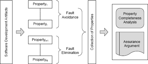
FIGURE 7.15 Establishing collections of properties about a set of software artifacts.
7.11 Misconceptions about Software Dependability
There are several widely held technical misconceptions about software dependability. In practice, these misconceptions tend to affect the choices of technology that engineers and managers make. The most commonly held misconceptions are:
Software defects are only introduced during implementation.
A common misconception is that software defects are only introduced during preparation of the source program and can only be found by testing. As should be evident from earlier parts of this book, this combination of ideas is a dangerous fallacy since both parts are wrong. Defects in the requirements, specification, and design of a software system are best dealt with in the requirements, specification, and design phases of development, not the subsequent implementation phase. For example, techniques for fault avoidance and fault elimination in specifications are far more effective than testing the subsequent implementation.
Experience has shown that, for many systems, the majority of software defects are actually introduced in the specifications but usually not found until testing. In some industries that develop systems with high dependability requirements, roughly two thirds of the defects that are detected either during testing or in the field were introduced in the specification. This statistic makes fault avoidance and elimination in specifications of crucial importance.
Small organizations cannot afford fault avoidance and elimination.
Another common misconception is that the cost of fault avoidance and fault elimination techniques early in the development process is not needed by and is beyond the means of a small organization. In view of the cost of failure for virtually all modern systems of any significant size and for all safety-critical systems, employing fault avoidance or fault elimination to the maximum extent possible is likely to be cost effective. The cost of a single failure can easily exceed the cost of any of the techniques discussed in this book. In addition, even if defects are located during development, the cost of removal usually exceeds the cost of applying rigorous development techniques. In dealing with software dependability, the cost of applying more sophisticated techniques can often be far less than the cost of not applying them. Defects that could have been avoided or eliminated during development might not get caught later.
Fault avoidance and fault elimination are impractical.
A third common misconception is that, in practice, when developing realistic software systems, employing ideas such as those discussed in this book is not possible. Various reasons are given to justify this claim. For example, some argue that proper specifications cannot be written, because the details of what the system is to do are not known when development begins. Such incompleteness is real and has to be addressed. But incomplete detail does not mean that specifications cannot be developed. Incompleteness means that specifications cannot be complete at the outset. Developing a partial specification and then determining the details of what is missing, perhaps by developing prototypes or holding detailed discussions with the customer, can be a perfectly rigorous process. Development risks such as incomplete specifications are part of the development process, but this does not mean that the process cannot be rigorous.
Project personnel cannot use the techniques.
A final common misconception is that software has to be written using tools and techniques with which the developers are familiar even if those tools and techniques are not entirely suitable for the subject software. C, for example (or one of its derivatives such as C++), is rarely suitable for use in developing safety-critical systems, yet C is often used and this use justified by claiming that C is familiar to developers. The benefits of other languages in terms of fault avoidance and fault elimination are lost as a result. In practice, learning an unfamiliar technology is rarely prohibitive, especially when major benefits ensue, and achieving dependability relies in many ways on employing the best technology available.
Key points in this chapter:
♦ Software can be very fragile. A large software system can fail because of a mistake in a single line of the source code.
♦ The software lifecycle helps identify both the points at which faults can arise and the points at which we might be able to deal with the faults.
♦ Validation can be thought of as answering the question: “Did we build the right thing?” and verification can be thought of as answering the question: “Did we build the thing right?”.
♦ Correctness by construction is a concept in which developers attempt to create correct software by virtue of the technology used in construction.
♦ Formal methods provide a variety of analytic results about software artifacts.
♦ Model checking is an analysis technique for establishing properties of software by state space analysis.
♦ Model-based development is a technique for synthesized software from specifications written in application-specific languages.
♦ Various techniques can be utilized to effect software fault avoidance.
♦ Various techniques can be utilized to effect software fault elimination.
♦ A combination of techniques should be used to avoid and eliminate as many types of software fault as possible.
Exercises
1. Write a natural-language specification for a program that takes an integer in the range 0 to 10,000 and determines whether the year is a leap year.
2. Defects in software are a serious problem for safety-critical systems, but accidents occur as a result of defective data also. Things like defective navigation data, configuration data, and weight and fuel data have caused accidents even though the software was right. Discuss the application of fault avoidance to data.
3. Discuss the application of fault elimination to data.
4. Discuss the application of fault tolerance to data.
5. Explain the claim: Software engineering uses testing to establish a conclusion whereas other branches of engineering use testing to confirm a conclusion.
6. In Hall’s paper, “Seven Myths of Formal Methods” [54], myth number 1 is “Formal Methods Can Guarantee That Software Is Perfect”. In your own words, explain why this is a myth. Do not merely repeat the argument from the paper. Rather, show that you are aware of the argument details.
7. For myth 5 in Hall’s article [54], discuss the overall economic effect of formal methods.
8. For myth 12 in Hinchey and Bowen’s article [20], discuss the role of formal methods in software such as games, word processors, and operating systems.
9. Carefully explain the application of verification and validation to the requirements, specification, and implementation of a software system.
10. Explain why the use of formulas in spreadsheets is an example of model-based development.
11. Mathworks Simulink is a popular model-based development system. Itemize as a bulleted list the sources of software defects for a binary program created using Simulink and other associated utilities.

Compute the total time needed to test the program if the test coverage required is to execute all paths of the program fragment and each execution requires one millisecond.
13. Several years ago, the Navy chose Microsoft Windows NT as the basis for many shipboard systems. The result was what is referred to as the USS Yorktown incident:
![]()
The use of Commercial-Off-The-Shelf (COTS) computer components (both hardware and software) in safety-critical systems is viewed as highly desirable by developers and highly problematic by regulators. The advantage is the low cost. The disadvantages are many and obvious. Despite the problems, the use of COTS in systems requiring high dependability is continuing.
(a) Most COTS operating systems were designed for general-purpose use, not safety-critical use. Could a COTS operating system be modified and/or enhanced for use in a safety-critical application? If so, how? If not, why not?
(b) A COTS component that is often not recognized as such is a compiler. Compilers are essential for building safety-critical systems. Should COTS compilers be used for safety-critical systems? If so, why? If not, why not?
(c) Open-source software is viewed as a technology that might be exploited for safety-critical systems, because the source code of the software is open to public scrutiny. Does this fact make a difference to the suitability of the software for use in a safety-critical system? If so, why? If not, why not?
(d) COTS software is usually only available in binary form with no information about how the software was built. Such information is usually viewed as proprietary. This leaves open the question about what trust might be placed in the software as a result of knowing what the development process was. Discuss the possibility of an approach to trust in COTS software based upon a confidential assessment undertaken by a trusted third party.