
![]()
Embedded Computers and Going Wireless
In this chapter, we’re going to cover two topics, which are very popular with multimedia programming and creative coding. The first topic is the embedded computers. These are small and low-cost computers that can be embedded into projects, hence their name. There are quite some embedded computers around, and we’ll talk about which to choose for your needs.
The second topic of this chapter is the wireless use of the Arduino. This is possible with two ways. One way is using a Bluetooth module with the Arduino, which is a quick and low-cost solution. The Bluetooth is widely used, and there are dedicated modules that work with the Arduino. The other way is using the XBee transmitter/receiver modules, which work nicely with the Arduino. These modules are not so expensive, low-power, and easy to configure radios. There are many boards that help combine them with various Arduino types (usually these boards are called shields), so you can easily find a board type that fits your project needs.
In this chapter, you’ll learn how to
- log in an embedded computer remotely, using your laptop (or desktop)
- navigate through the Linux operating system
- find and install software on a Linux computer
- launch software on a Linux computer
- do basic editing in text files on Linux
- transfer files between your computer and an embedded computer
- change the IP address of an embedded computer
- shut down an embedded computer using a script
- configure the XBee transmitter/receiver modules
- use the XBee modules to make the Arduino wireless
Before You Begin
Usually these are open source hardware computers, which run on Linux. Therefore, we’re going to cover some Linux—navigating through the operating system, installing software, and launching software on a Linux computer. In some of this book’s projects, where we’re going to use embedded computers, we’re going to write some small scripts as well, to make the computer plug-and-play.
The goal of using such a device is to use the capabilities of a computer, without using the interface we’re familiar with, the screen, the keyboard, and the mouse. Since we will be building interfaces with the Arduino, we’re going to use these devices headless, meaning without a monitor to display information. To do that we need to configure a computer in such a way that it will launch all software we want on boot, and quit all software when we want to shut it down. Using scripts enables these features and helps us finalize our projects.
Even though we’re not going to deal with scripts in this chapter, you’ll learn how to use a text editor on Linux, as this will prove very helpful with writing scripts and debugging certain parts of an interface that might occur (like crashes or immediate shutdown as soon as a patch loads), and configuring certain settings of the embedded computer. We’re going to do all this using our own laptop or desktop, without needing an extra screen, keyboard, and mouse, to use the embedded computer. We’ll log in the embedded computer using an Ethernet cable and simple Unix commands, and we’ll use our laptop’s/desktop’s screen, keyboard, and mouse to interact with the embedded computer.
In some projects in this book, we’re going to use the XBee because it frees the performer from having a bunch of cables hanging out. Usually, we need to use the XBee (or Bluetooth) when we’re not using embedded computers, as with the latter, it’s probably pointless to make the project wireless, since the computer will be built-it the project’s interface. So this chapter will cover two sort of complementary topics, which will prove very handy as we build the interfaces of this book’s projects.
Parts List
Table 3-1 lists the parts that you’ll need for this chapter.
Table 3-1. Parts List
Part | Quantity |
|---|---|
Raspberry Pi or other embedded computer | 1 |
SD card | 1 microSD 8GB, class 10 |
Charger | 1 5V 1A maximum. A smartphone charger will do. |
Ethernet cable | 1 |
XBee radios | 2 (series 1 or 2) |
Arduino XBee shield | 1 |
XBee USB Explorer | 1 |
Arduino Uno | 1 |
Bluetooth module (HC-06) | 1 |
Why Use Embedded Computers?
When building a project and putting it in an enclosure, it’s very likely we don’t want to carry a laptop to use the interface we’ve built. An embedded computer helps us build a stand-alone interface, which can also be plug-and-play. Think of digital synthesizers. Being digital means that they function with a computer, which does all the calculations to produce the sound. Imagine a digital synthesizer that is only a controller (the keyboard and a few knobs), and you need to bring along a laptop for it to work. This scenario doesn’t sound very appealing. Using a computer to make electronic music has gained so much ground, that the laptop has become a standard piece of equipment.
In the past few years, the revolution of the Arduino was followed by the revolution of the embedded computers. Of course, they are nothing new because they have been around for years (many devices that you use every day have an embedded computer). Over the past few years, new, easy-to-use, open source, and low-cost embedded computers have made their appearance, making them more easily accessible. Consequently, communities have been created around each embedded computer, where people share work and knowledge and help each other with problems that may occur.
All this have brought the DIY communities to a very high level, as it is easier than ever before to create lots of things, from hobbyist to professional level. The Maker movement has grown to a great extent. You see people realizing DIY projects all over the world. This book is a result of the appearance of such tools, as it realizes projects that the reader is encouraged to try at home.
Which Embedded Computer?
Again, there are quite a lot of embedded computers around, but I’ll mention the most popular. The computer with the wider use is by far the Raspberry Pi, https://www.raspberrypi.org/. This is a small computer (well, all embedded computers we’ll talk about are small), used by a very wide community, and gets most of the attention when it comes to embedded computing. It runs on a Linux flavor based on Debian, called Raspbian, but other Linux distributions are available. The latest version has a special Windows 10 version, especially for the Raspberry. It is the only embedded computer, which can run on an operating system other than Linux or Android.
Another very popular computer is the BeagleBone Black, http://beagleboard.org/black. Till recently, it was quite more powerful than the Pi, but the latest Pi version has a processor, which runs a little bit slower than the BeagleBone Black, but has four cores, whereas the BeagleBone Black has only one. Still, this is a very nice low-cost embedded computer, which you should bear in mind. One disadvantage I find with the BeagleBone Black is that it lack an audio output jack, and can play audio only via its HDMI, whereas the Pi (and the other boards I’ll mention here) does have an onboard audio jack, and that makes things quite easier.
The third embedded computer in our list is the Udoo, http://www.udoo.org/. This one is rather special because it is a computer with an embedded Arduino Due (a 32-bit Arduino board)! At the time of writing (August 2015), a new version is being released with an Arduino Uno pinout, and a few on-board sensors. The two pre-existing versions are a dual and a quad core computer, with an on-board Arduino Due. This is a powerful computer that integrates an Arduino, so it can make things very flexible. It comes at a higher price though (the Arduino is included in this price), and it has quite a bigger size (it’s still small), so sometimes it ca prove not very appropriate as being a one-board machine, reduces casing flexibility.
The last embedded computer we’re going to look at is the Odroid, http://www.hardkernel.com/main/main.php. This is the most powerful of all four computers. There are a few different versions available, where the lowest performance one has a higher performance than all the computers mentioned here. There are other powerful versions of the Odroid, but it’s not really necessary to look at them at this point. This computer has the smallest size as well, so one might really consider one of these boards for a project. The latest versions of the Odroid don’t include an onboard audio jack, like the BeagleBone Black, but even an older version provides very poor audio quality. You should either use the HDMI for audio (there are some shields for that), or an external sound card.
Having covered shortly these four embedded computers, we’ll stick to the first one, the Raspberry Pi, for a few reasons. It might be the one with the lowest performance, but still it’s powerful enough to host some of this book’s projects. Price is one reason, even though the Odroid-C1+ can compete with it. The latter is missing the audio jack feature, so the Pi wins this round, as we’ll be dealing with audio throughout this book. Another reason is its community. The other boards do have an active community, but the one of the Pi outnumbers them all, and this is a good reason for one to choose one board over another. The Pi is so popular that even Miller Puckette, the maker of Pd, has a compiled version of the latest Pd-vanilla for the Pi. He has compiled one for the Udoo as well, but with the previous things in mind, again the Pi wins this round over the Udoo. One last reason is that, apart from the on-board audio jack (which provides a restricted quality audio) there dedicated external sound cards, which mount on top of the Pi, increasing its performance, and making it quite compact, easy to fit in an enclosure. We’re not going to cover the external sound card topic in this book, but it’s good to know in case you want to extend one of your projects.
All these reasons lead us to the Raspberry Pi, which we’ll use throughout this chapter. If you want to follow this chapter, it’s better to get an embedded computer, as only by reading the instructions, you’re not going to get as familiar with all processes described here. If you want to use another embedded computer, you’re free to do so. The steps we’re going to take are similar for all boards. You’d better use a Debian Linux flavor, however, as we’ll be working with the Debian flavor for the Raspberry Pi: Raspbian. Still, even if you use Ubuntu Linux, it’s OK, since Ubuntu is Debian-based. If you don’t want to get an embedded computer yet, and leave it for later, you can skip this chapter and come back to it when you have one. Not all projects of this book will use the Raspberry Pi, so you’ll be able to build quite some of the projects without one. You can buy a Raspberry Pi (or whichever computer you want) from its web site, or ask your local electronics store whether they distribute it.
Getting Started with the Pi
Now that you have your new Raspberry Pi, let’s start using it. The first thing you’ll need to do is install the Linux image to an SD card (image is the way to refer to the OS distributions. The SD card should be at least 8GB, preferably class 10). Go to the DOWNLOADS section of Raspberry’s web site, and click the Raspbian icon (not the NOOBS one). As of September 2015, there are two Raspbian images: a Jessie and a Wheezy. I recommend downloading Jessie, which is more up-to-date, since Wheezy is the previous Debian OS. On the Jessie page, you can get instructions for writing the image to your SD card. It’s beyond the scope of this book to get you through the steps required, but the instructions provided by the web site should be sufficient. If you encounter problems, you can sign up the Raspberry’s forum and search the archives, or ask for help. I’ll now assume that you have written the Raspbian image to your SD card, and we’ll take it from there.
Since we’re not going to use an external monitor, a keyboard, and a mouse to use the Raspberry, we’ll have to log in remotely, using our laptop/desktop. You’ll need an Ethernet cable to connect the Raspberry to your computer. If you have a Mac without an Ethernet port, you should get an Ethernet converter, to be able to log in your Pi. You’ll also need a changer (a smartphone charger will do, as the Pi uses a micro USB for power, and 5V/500mA will be enough power), and access to a router with Internet connection. Connect the Pi to the router with the Ethernet cable and power it up. Make sure your laptop/desktop is connected to the same router and that you don’t have any firewalls enabled that could block the communication with the Pi.
First, you have to find the IP address of the pi. The simplest way to do this is to log in the router. Most Internet services give access to the IP addresses of devices connected to them, through the router. To log in the router open an Internet browser and type the router’s IP address to the URL field. This should be something like 192.168.1.1, where the last two fields will be either a 1 or a 2 (most likely the very last will be 1 anyway). Try all four combinations until you get connected to the router. When you get in the router’s home page, you’ll be asked for the router’s password, and maybe the username as well. Usually they are both admin, so if you’re lucky enough, you’ll be logged in. If it’s not admin, it’s very likely that the password for the device is written in the back of the router, so use that. On the router’s home page, browse to the list of connected devices; it could be called Status or something similar—routers are all different. There you should see the IP address of the Pi. You’ll know it’s the Pi because its name will be displayed. In case your router doesn’t provide this feature, you’ll have to use another way. There should be quite some different ways to achieve that, depending on your platform (Linux, OS X, Windows). Nmap is one solution, which runs on all three platforms. Go to Nmap’s web site (http://nmap.org/download.html), and install it on your computer. The fastest way is to type the following in your computer’s terminal:
nmap raspberrypi.local
This prints some information about the Pi, including its IP address. On Windows, use the Zenmap GUI provided by Nmap, and use the same command on Zenmap’s window.
If you’re using another embedded computer, I don’t really know how to get its IP from its name, but typing the following will give all the active hosts in your network:
nmap 192.168.2.0/24
The first three fields should be the same for your computer’s IP (and the same with your router). This will print a few different IPs, one of which should be the IP of your embedded computer.
If all this seems a bit overwhelming, there’s a simple, not very efficient way to find the IP. Check your computer’s IP (if you’re connected wirelessly, check the wireless IP, otherwise check the Ethernet IP of your computer). If you’re at home, there shouldn’t be many devices connected to the network, so if your IP is for example, 192.168.1.3, then it’s very likely that the Pi’s IP will be 192.168.1.4, or something similar. In general, the first three fields will be the same, since the two devices are connected to the same network, and the last field will be different, where it should be a sort of an incrementing number. Since your laptop was connected to the router prior to the Pi, the Pi should have a greater number in that field. Once you have the IP, it’s time to connect to the Pi (if you’re trying to guess the IP, just repeat the following process until you are logged in). On OS X and Linux, the process is the same, but on Windows, it differs, so we’ll go through it immediately afterward.
Getting Your Computer’s IP
Since we’ll need to know our computer’s IP, let’s see how we can find it. On Linux, you can get it from the terminal by typing:
ifconfig | grep "inet " | grep -v 127.0.0.1 | awk ’{print $2}’
This will print the IP address of the Wi-Fi, and the Ethernet port. In this case, we care about the Wi-Fi.
On OS X, you can get it from the terminal by typing:
ipconfig getifaddr en1
Another way is to open your System Preferences by clicking the apple icon on the top-left part of your screen and choosing System Preferences…. Select Network under Internet & Wireless, and then on the Wi-Fi tab on the left side, and you’ll get your IP address.
On Windows, Go to Control Panel ![]() Network Connections
Network Connections ![]() Wireless Network Connection, and under the Support tab, you’ll find your IP address. This is tested on Windows XP, which is now obsolete, and Windows versions tend to change quite a lot of things in their OS upgrades, so the process might be a bit different on your Windows machine. Still, this information should give some insight as to where you should look for your IP address.
Wireless Network Connection, and under the Support tab, you’ll find your IP address. This is tested on Windows XP, which is now obsolete, and Windows versions tend to change quite a lot of things in their OS upgrades, so the process might be a bit different on your Windows machine. Still, this information should give some insight as to where you should look for your IP address.
Logging in the Pi from OS X and Linux
On OS X make sure you have XQuartz installed, http://xquartz.macosforge.org/landing/. Open a terminal window (on OS X go to Applications ![]() Utilities and launch the Terminal.app; on Ubuntu press Ctrl+Alt+T, or search your files) and type the following:
Utilities and launch the Terminal.app; on Ubuntu press Ctrl+Alt+T, or search your files) and type the following:
ssh -X [email protected]
ssh stands for Secure Shell, which is a protocol for getting a secure access to a remote computer, like the Pi. Replace the x’s in the two last fields of the IP address with the ones of the IP of the Pi. The -X character (called a flag, which is recognized by the hyphen symbol) means that we will be using X11 (XQuartz on OS X) so that the Pi can display its GUI. Depending on the version of the OS X you’re using, you might need to launch XQuartz prior to typing this command in the terminal. Hit Return and your computer will connect to the Pi. The first time that you connect, you’ll get a warning concerning the authenticity of the host (the Pi) and you’ll be asked whether you’re sure that you want to continue. Type yes and hit Return. Then you’ll be asked for the password of the Pi, which is raspberry. As you type it, you won’t see anything in the terminal (like the top of Figure 3-1, there’s nothing seen after password), but the password will actually be typed. Once you enter the password, hit Return and you’ll be logged in the Pi. Figure 3-1 shows the prompt of your first log in to the Pi.
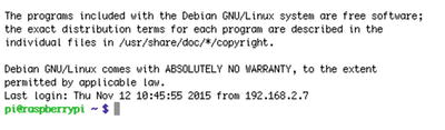
Figure 3-1. First log in to Pi
In Windows, you’ll need a couple of things before you log in your Pi. First, you’ll need an X server, which the Pi will use to display its GUI on your computer. There are several X servers around, including MobaXterm, http://mobaxterm.mobatek.net/, Xming, http://www.straightrunning.com/XmingNotes/, and Cygwin, http://x.cygwin.com/. Choose whichever you like and install it on your computer. You’ll also need PuTTY, http://putty.org/. Choose the first link on its download page, putty.exe. Next, launch the X server you have installed and run putty.exe. (I use Xming, and when launched, there’s a small icon on bottom left of the screen, no window opens.) Figure 3-2 shows the PuTTY window.
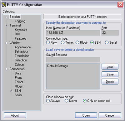
Figure 3-2. PuTTY window
Type the Pi’s IP in the Host Name (or IP address) field. (In Figure 3-2, I typed the IP of my Pi. You should use the IP of your Pi.) The SSH selection underneath should be selected by default, which we want. SSH stands for Secure Shell, which is a protocol for getting a secure access to a remote computer, like the Pi. Before you click Open, go to the right-side menu and click SSH. Next, click X11. Figure 3-3 shows this menu. Make sure that you select the Enable X11 forwarding tick box. Once you’ve done that, click Session on the left-side menu, and you’ll get back to the login window, as shown in Figure 3-2. In this window, you can save your session, but don’t do it just yet, because we’re going to change in IP of the Pi, so you’ll have to be a bit patient.
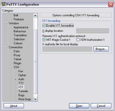
Figure 3-3. X11 menu in PuTTY
Once you have all this done, click Open. You’ll get a window telling you that the host is not registered in your computer, as shown in Figure 3-4.
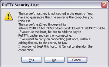
Figure 3-4. PuTTY host registration window
Click Yes and you’ll get to the login window, shown in Figure 3-5. In the beginning there will be the first line only, which reads Login as:. Type pi and hit Return. You’ll be asked for Pi’s password, like in Figure 3-5 (don’t mind the IP that appears in the Figure). Type raspberry. As shown in Figure 3-5, the password won’t be visible as you type it, but the computer will receive it. In Unix terminals (Linux and OS X), passwords are hidden from the monitor. If you typed the password correctly, you’ll be logged in. Congratulations!
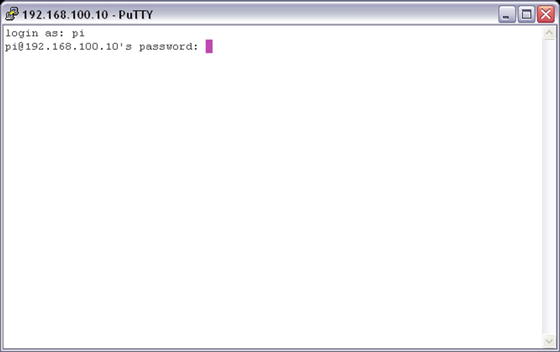
Figure 3-5. PuTTY login window
Configure the Pi
The steps from now on are common for all three operating systems (Linux, OS X, and Windows), since we’re now logged in the Pi, and no matter what OS you use, we’re now in Linux. The first time you log in you’ll need to configure your Pi. To do this run the following command:
sudo raspi-config
This will lead you to the Configuration Tool, which is shown in Figure 3-6 (other embedded computers might prompt you to configure them and guide through the configuration).
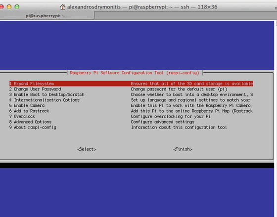
Figure 3-6. Raspberry Pi’s software configuration tool
To navigate in this tool, you have to use the arrow keys. The up and down arrow keys will navigate through the options on the left side of Figure 3-2, which are numbered. The right arrow key will get you to <Select>, and if you hit it once more, it will get you to <Finish>. Clicking the left arrow key will get you back to the configuration options. Hit Return on the first option, 1 Expand Filesystem. This will take just a moment. Hit Return to get back to the options, and navigate to 7 Overclock. Hit Return and in the options, choose High 950Hz. Hit Return to enable it and go back to the main menu. Click the right arrow key and navigate to <Finish>. You’ll be asked if you want to reboot now. Click yes and the Pi will reboot. This means that the connection between the Pi and your computer will be lost. Wait until the Pi reboots and log in again using the ssh command for OS X and Linux, and PuTTY for Windows, as before.
Navigating Through the Linux system
Now that we’ve logged in the Pi, let’s navigate through its system. Since we’re logged in the Pi remotely from another computer, we’ll do all navigation, folder creation, file management, and so forth through the terminal. Figure 3-7 shows the prompt of the Pi’s terminal.

Figure 3-7. Raspberry Pi’s command-line prompt
In green, you see the name of the user, which is pi, logged in to the “raspberrypi” device. The dollar sign is the user sign, called the prompt. If you’re not a super user (called a root), but a plain user, you get this prompt. If you’re root, you get the # prompt. Go ahead and type the following: ($ or # will be included in all commands from now on to clarify the user. You shouldn’t write it yourself in the terminal because it is already there.)
$ whoami
You should get pi. This is a Unix program telling you what kind of user is currently using the computer. Pi’s default user is called a pi. Now type the following:
$ ls
This is a shortcut for list. “ls” is a program that prints to the monitor the contents of the current directory (by directory, we refer to what is usually called a folder). It should read python_games. To see what kind of file this is, type the following:
$ file python_games
Note that all commands are separated from their arguments with a white space. The first word (or combination of few letters) is the command, and afterward the arguments follow, don’t mix them in one long word. The preceding command should print python_games/: directory. We can see that this is a directory by default on the Raspbian image. Directories appear is in blue to distinguish them from other types of files. Now type the following:
$ pwd
This stands for present working directory, which is a program that prints the path to the directory you currently are. This should give you /home/pi. This is the home directory of the user “pi”. Now let’s create a new directory in our home directory. Type the following:
$ mkdir pd_patches
mkdir stands for make directory, which is a program that creates directories. pd_patches is the name of the directory we want to create, which we pass as an argument to mkdir. If you type ls again, you’ll now see two directories, one called python_games and another one called pd_patches. To go into the new directory, type the following:
$ cd pd_patches
This stands for “change directory and we provide the directory we want to go to as an argument (here pd_patches). Now if you type pwd again, you’ll get /home/pi/pd_patches. Notice that Linux has a tree structure, where / is the hard drive of the computer, and subsequent directories are being separated by forward slashes. The new directory we created is in the pi directory, which is in the home directory, which is in the / directory, which is the hard drive of the Pi. Now let’s go back to our home directory. Type the following:
$ cd ..
The double dot means one directory up. This will get us back to /home/pi. Now create a directory called pd_abstractions, inside the pi directory, the same way you did with the pd_patches directory. Go to this directory using cd, but do the following. Type the following:
$ cd pd_a
Hit the Tab key. You’ll see the whole name of the directory appear on screen. The Linux command line has tab completion, which means that if enough letters of a directory are provided, hitting Tab will give the rest of the name (by “enough” I mean that there’s no name clash. In /home/pi there’s only one directory starting with pd_a, the newly created pd_abstractions). This is a good way to use the terminal, not only because it saves you some typing, but it’s also less error-prone since the computer finds the name of a directory, so there’s no way you’ll make a typing mistake.
Let’s go back to our home directory (by “home” I mean the /home/pi directory, not /home) and create another directory. Now we want to create a directory inside the pd_abstractions directory. We could have created it while we were in that directory, but we came back to the home directory for practice and to better understand the Linux tree structure. We’ll create a directory to store the abstractions that deal with the Arduino, so we’ll call it arduino_abs. In your home directory, type the following:
$ mkdir pd_abstractions/arduino_abs
Now go to that directory using cd. Type the following:
$ cd pd_a
Hit the Tab key, and you’ll get cd pd_abstraction/. Type a and hit Tab. You’ll get cd pd_abstractions/arduino_abs/. Hit Return and you’ll be taken to the newly created directory. To go back to the home directory, type the following:
$ cd ../..
This will take you two directories up, where the home directory should be. Another way to navigate back to home, from whichever directory you are (as user “pi”) is this:
$ cd ~
The tilde character means “the home directory of the current user.”
Editing Text Files in Linux
Now that we’ve navigated a bit through the system, let’s do a bit of text editing. Raspbian, and many other Linux distributions, has a text editor preinstalled, which runs in the terminal. This editor is called nano. There is also the vi text editor, but I prefer to use nano because it’s very simple and easy to use, so we’ll use that in this book. In your home directory, type the following:
$ nano test_text.txt
The nano editor will open, as shown in Figure 3-8.
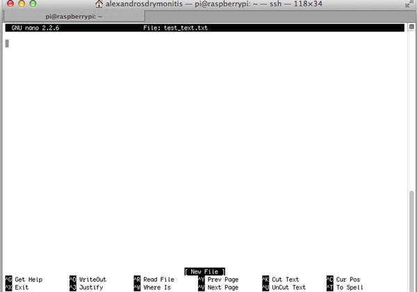
Figure 3-8. The nano text editor
Go ahead and type something; for example, “This is a test text using the nano text editor.” Press Ctrl+O (if you’re on OS X, still use Ctrl, as now we’re actually on Linux) and at the bottom you’ll see the prompt: File Name to Write: test_text.txt. Hit Return. At the bottom, in the place of [New File] (shown in Figure 3-8), you’ll see [Wrote 1 line] (or as many lines of text as you entered). Press Ctrl+X to get out of nano and back to the Unix prompt. Now type ls to get a list of the present directory’s contents, including the three directories (python_games, pd_patches, and pd_abstractions). You’ll see the new text file, test_text.txt. To see the file’s contents, type (use tab completion):
$ cat test_text.txt
And you’ll get the text that you just wrote in nano. “cat” is short for concatenate, which is a program to concatenate files. Using it this way, we can just see the contents of a file, without entering an editor. We’ll be using nano, mostly for writing some simple scripts to tell the Pi to launch certain software on boot or to shut it down, but also in case we need to debug a Pd patch that might cause a crash or an automatic shutdown. This is in case we cannot edit it in Pd itself, but only in its textual form.
Since the text file we wrote is only a test to see how nano works, let’s delete it. To do this type (remember to use tab completion):
$ rm test_text.txt
rm stands for remove. When you use rm, the file is completely deleted, instead of going to some “trash” directory from where you can delete it later on. Also, the Pi doesn’t ask you if you’re sure whether you want to delete the file or not, so be very careful when you use it, as you might delete a file you don’t really want to, and you won’t be able to retrieve it.
Installing Software
It’s time to install some software on your Pi.
Installing Pd
Let’s start with Pd. To install it, type the following:
$ sudo apt-get install puredata
“sudo” is a Unix program that enables us to run commands with superuser privileges. Whenever we want to use a terminal program, but we are denied access to it, we use sudo. To install software, we need superuser (root) privileges, so we have to use sudo. apt-get install searches the Raspbian repositories for the software we want, “puredata”. The repositories of Linux distributions are storage places with software for each distribution. apt-get install searches for the software and install it without us needing to compile the software from source. Once it finds it, it will print some data to the monitor, and it will then inform you about the amount storage place this software will need, and ask you if want to continue, like the following text:
Do you want to continue [Y/n]?
Type y and the installation will go on. The terminal will type quite some data about the installation process, and when it’s done you’ll get back to the $ user prompt. Installing Pd this way will actually install Pd-vanilla, so you’ll need to install some external libraries. To find which ones are available in the Raspbian repository, type the following:
$ apt-cache search "^pd-"
We don’t need to use sudo for apt-cache search, since it only searches the repositories, but doesn’t install any software to the computer. This will print a list with all available external libraries in the Raspbian repositories. To enhance our Pd, we’ll install some of them but not all. Go ahead and type the following:
$ sudo apt-get install pd-arraysize pd-comport pd-freeverb pd-ggee pd-iemmatrix pd-list-abs pd-mapping pd-pan pd-pdstring pd-purepd pd-zexy
Again, type y for yes when asked if you want to continue with the installation. This will install all the libraries to a directory created by the Pd installation, which is /usr/lid/pd/extra. After the installation is done, type the following:
$ ls /usr/lib/pd/extra
This will print the directories of the installed external libraries:
Gem arraysize comport cyclone freeverb~ ggee iemmatrix libdir list-abs mapping maxlib pan pddp pdstring pix_drum pix_fiducialtrack pix_mano purepd zexy
There are few more packages that were installed when we installed Pd, such Gem, pix_fiducialtrack, and the ones we installed ourselves.
Launching Pd
To launch Pd, you must type the following command in Pi’s terminal:
$ /usr/bin/pd
What we’re doing here is call an executable file, called pd, which is in the /usr/bin/ directory. This file launches Pd (you can launch Pd in a similar way on OS X too, since it’s also a Unix system). The first time you launch Pd, it might take a while, and you’ll see the “watchdog signaling pd…” message in the terminal. Don’t worry, Pd will launch and these messages will stop appearing on your screen. When Pd launches, the first thing to do is test if the audio is working properly (we didn’t do this in Chapter 1 because we started building patches from the beginning, and the first patch did essentially the same thing). Go to Media ![]() Test Audio and MIDI…, and the patch shown in Figure 3-9 will open.
Test Audio and MIDI…, and the patch shown in Figure 3-9 will open.
As the comment on top of the patch states, this patch is made for testing the audio and MIDI connections in Pd. Plug a pair of headphones into your Pi and click 80 on the left radio underneath TEST TONES. This should create a (low in volume) sine tone at 440 Hz. To make it louder, type 100 in the number atom underneath the radio. You can also listen to Pd’s white noise by selecting noise. If you have a MIDI device, you can plug it in the Pi and relaunch Pd to see if that is also working, as we’ll use a MIDI keyboard in one of this book’s projects.
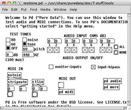
Figure 3-9. Test Audio and MIDI… Pd patch
Setting up External Libraries in Pd
Once you’ve tested audio in Pd, you should set the external libraries paths to Pd’s search path. Go to Media ![]() Preferences
Preferences ![]() Path… and you’ll get the Path window. Click New and the window to add a new patch will open, shown in Figure 3-10. Click the Directory: to get the pop-up menu, which should display three directories, /, /home, and /home/pi. Click / and navigate to /usr/lib/pd/extra. From there, choose the libraries you’ve already installed, one by one, all but zexy and iemmatrix.
Path… and you’ll get the Path window. Click New and the window to add a new patch will open, shown in Figure 3-10. Click the Directory: to get the pop-up menu, which should display three directories, /, /home, and /home/pi. Click / and navigate to /usr/lib/pd/extra. From there, choose the libraries you’ve already installed, one by one, all but zexy and iemmatrix.
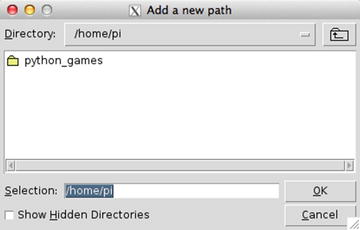
Figure 3-10. Add new path window
Once you’ve selected the libraries, you search path window should look like Figure 3-11. Click Apply and then OK so that the new settings will be enabled.
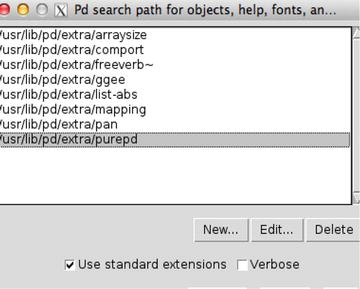
Figure 3-11. Selected libraries in Pd’s search path window
For the other two libraries, zexy and iemmatrix, we need to do something else to add them to Pd. Go to Media ![]() Preferences
Preferences ![]() Startup… and the Pd libraries to load on startup window will appear, as shown in Figure 3-12. In the Startup flags: field type -lib zexy -lib iemmatrix, like in Figure 3-12. Click Apply and then OK to set these features as well.
Startup… and the Pd libraries to load on startup window will appear, as shown in Figure 3-12. In the Startup flags: field type -lib zexy -lib iemmatrix, like in Figure 3-12. Click Apply and then OK to set these features as well.
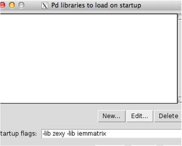
Figure 3-12. Startup flags Pd window
Now, to test the new setting, you must quit and relaunch Pd. Go to File ![]() Quit, or press Ctrl+Q. Go back to the terminal and relaunch Pd, by typing /usr/bin/pd. Figure 3-13 shows the Pd console with the zexy and iemmatrix libraries loaded. You should have the same comments on your console.
Quit, or press Ctrl+Q. Go back to the terminal and relaunch Pd, by typing /usr/bin/pd. Figure 3-13 shows the Pd console with the zexy and iemmatrix libraries loaded. You should have the same comments on your console.
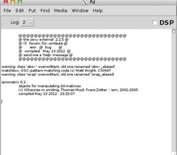
Figure 3-13. Pd’s console with the “zexy” and “iemmatrix” libraries loaded
Test a few objects that we will very likely need for this book’s project. Open a new patch and try to create the following objects (OS X users, all shortcuts that use Cmd on OS X, should be replaced by Ctrl, as this is Linux): [arraysize], [comport], [shell], [list-drip], [uzi]. If Pd can create all the objects, then everything is fine. If there are any objects that cannot be created, go to the search path window and check that you’ve set everything as suggested.
You should also test the two libraries we set via a startup flag: zexy and iemmatrix. Try to create the following two objects: [limiter~], and [mtx_*~ 4 4 20] (there might be a possibility that the second object can be created like this [mtx_mul~ 4 4 20], instead). If Pd can create both these objects, then again all is fine. If there’s any problem, go to the startup window and check if the names of the two libraries appear in the window (not the Startup flags: field, but the white space in Figure 3-12). Here’s something that might be useful to some users of OS X computers: to be able to right-click in the Pi, you need to edit the Preferences of XQuartz. Under the Input tab, you might need to select the Emulate three button mouse tick box. On some computers, it might not be necessary, but you may need it on newer Mac computers.
Installing Arduino
Now that we’ve tested Pd’s audio and all the external libraries we want to use, we can go on and install the Arduino IDE to our Pi. As with Pd, to install Arduino, type the following:
$ sudo apt-get install arduino
This will take you through the same process as with Pd, and it will install the Arduino IDE to the Pi. Installing the Arduino IDE with apt-get creates a directory called sketchbook on your home directory (/home/pi) to save your sketches. When the installation is finished, type the following and the Arduino IDE will launch.
$ /usr/bin/arduino
You’ll get a few warning messages in the terminal, but that’s nothing to worry about. It will take a bit of time to launch, but eventually you’ll see a new sketch window on your screen. It doesn’t look exactly like the new sketch window of your computer’s IDE, because it doesn’t have the void setup() and void loop() functions already there. This is because the IDE we’ve installed is an older version than the one you have on your computer, if you installed it recently. Let’s first test if the Arduino IDE works properly, and then we’ll talk about versions. Go to File ![]() Examples
Examples ![]() 01.Basics and click Blink (the color highlighting is a bit different as well, because of the different version). This sketch, apart from being the first sketch to write/read when learning Arduino programming, also serves as a test sketch, to see that the IDE works fine with your board. Go to Tools
01.Basics and click Blink (the color highlighting is a bit different as well, because of the different version). This sketch, apart from being the first sketch to write/read when learning Arduino programming, also serves as a test sketch, to see that the IDE works fine with your board. Go to Tools ![]() Board and select your Arduino (if it’s the Uno, it will most likely be already chosen), and then go to Tools
Board and select your Arduino (if it’s the Uno, it will most likely be already chosen), and then go to Tools ![]() Serial Port to choose the Arduino port. You’ll probably get only one available port, /dev/ttyACM0, which is the Arduino port. Choose it and upload the sketch to your board. If all goes well, the integrated LED of the Arduino board should blink.
Serial Port to choose the Arduino port. You’ll probably get only one available port, /dev/ttyACM0, which is the Arduino port. Choose it and upload the sketch to your board. If all goes well, the integrated LED of the Arduino board should blink.
When launching software this way, we can’t use the terminal anymore, until we quit the software. Still, as we create Pd patches, or as we write Arduino sketches, we might want to change things in the Pi, and since the terminal is the only way, we need to launch software in such a way that enables us to use the terminal. This is done using the ampersand (&) at the end of the command. So, to launch Arduino, it’s best to use this:
$ /usr/bin/arduino &
This way, you’ll be able to go back to the terminal and do whatever you want, while the Arduino IDE is running. The same applies to Pd, of course.
Let’s Talk About Versions
Now let talk about software versions. The Arduino IDE version (which is on top of a sketch window) is 1.0.5, whereas the one we’ve installed on our computer from the Arduino web site is 1.6.5. That’s quite a version difference. To see which Pd version was installed, run this command:
$ /usr/bin/pd -version
Using the -version flag will output the version of Pd and will not launch the software. This should produce the following output:
Pd-0.46.2 (“”) compiled 07:48:11 Oct 29 2014
The latest vanilla version is 0.46-7, while we got 0.46.2 The version difference is not big, but it’s worth mentioning. If you’re using Raspbian Wheezy, then the version difference will be quite big, since you’ll get Pd-0.43.2 instead.
When we install software using apt-get, the program will search the repositories of the Linux distribution, and install the software it will find, that fits its argument (“puredata” and “arduino”). The repositories are not always up-to-date, so even though you’ll find the latest version of the software on its own web site, this won’t apply to a Linux repository as well. If you really want to get the latest version of software, you’ll need to download its source code and compile it yourself. This is beyond the scope of this book, so I won’t explain the process. Still, the software versions from the Raspbian Jessie repositories are good enough.
Exchanging Files Between Your Computer and the Pi
We’ve already created a directory called arduino_abs inside the pd_abstractions directory, to store the Pd abstractions that deal with the communication with the Arduino. We could launch Pd and make those patches again, but since we have downloaded them from the Internet, and there are quite some subpatches there, it will be a bit difficult to make them from scratch, plus it will be rather error prone, which could create bugs difficult to trace. A solution to this would be to either install an Internet browser on the Pi and go the web page where these abstractions are and download them, or transfer the already downloaded files form your computer to the Pi. The second solution proves to be the best, because once you know how to transfer files, you can do that for any kind of file, and not only for stuff you’ve downloaded from the Internet. On OS X and Linux, this is done the same way, but on Windows it’s different, so we’ll go through the OS X/Linux first and then we’ll talk about Windows.
Transfer Files from OS X and Linux to the Pi, and Vice Versa
Although there are some GUI programs to do this, like Cyberduck, a WinSCP Mac port, and some others, we’ll use the good old terminal to do this, since it’s rather straight forward and fast. In a new terminal window on your computer (not Pi’s terminal), type the following command, taking care of the white spaces between the scp command and the two arguments, the path to the files we’ll be transferring, and the destination computer:
$ scp /path/to/arduino/abstractions/serial*.pd [email protected]:/home/pi/pd_abstractions/arduino_abs
scp stands for secure copy protocol, which is a Unix program/protocol that copies files over an SSH connection. Replace /path/to/arduino/abstractions/ with the actual path, which, for example, could be ~/Documents/pd_patches/abstractions (on OS X, you can drag and drop the folder you want to navigate to in the terminal, and its path will automatically print). The two x’s in the Pi’s IP, with the actual values of the Pi’s IP address (tab completion will work for the path of your computer, but not for the path of the Pi). Notice the asterisk after the word serial. This is called a wild card and it means anything starting with serial and ending with .pd, because we want to copy both [serial_print] (actually [serial_print_extended]) and [serial_write], plus their help patches, which are called serial_print-help.pd and serial_write-help.pd, respectively. So instead of writing this command four times, we write it only once. Hit Return and you’ll be asked for Pi’s password (which is raspberry). Type it (remember, you won’t see the text as you type) and you should get the following in your terminal:
serial_print-help.pd                                           100% 4408     4.3KB/s   00:00
serial_print.pd                                                100% 8576     8.4KB/s   00:00
serial_print_extended-help.pd                                  100% 4446     4.3KB/s   00:00
serial_print_extended.pd                                       100% 8672     8.5KB/s   00:00
serial_write-help.pd                                           100% 2997     2.9KB/s   00:00
serial_write.pd                                                100% 9606     9.4KB/s   00:00
This informs us that all the files we wanted to transfer, have been transferred successfully.
We also want to copy the Arduino sketches we have that work with these abstractions. Remember that all Arduino sketches must be included in folders sharing the same name with the actual sketch. Using scp this way won’t work with directories (folders). We need to include a flag to do this. Go ahead and type the following:
$ scp -r /path/to/arduino/abstractions/serial*/ [email protected]:/home/pi/pd_abstractions/arduino_abs
Here we’re using the -r flag, which means recursive. This way the computer will copy not only the directory, but also its contents. This is necessary when we want to copy whole directories using the terminal. The fields of the command now are four, the command name, the -r flag, the path to the directories to copy, and the path to the copy destination. This means that we must insert a white space between each of these. Type Pi’s password when asked to. Now in the arduino_abs directory on your Pi, you should have two new directories: serial_print and serial_write. Each contains the corresponding Arduino sketch.
What if you want to transfer a file from the Pi to our computer? We use the same program, the other way round. Go to Pi’s terminal and create a test text file, like we did earlier, using nano. Type the following:
$ nano test_text.txt
Type some dummy text in there. Hit Ctrl+O and Return to save the contents, and then hit Ctrl+X to exit nano. Now, in your computer’s terminal (not the Pi’s; don’t confuse the two), type the following:
$ scp [email protected]:/home/pi/test_text.txt ~/Documents
Again, you’ll be asked for Pi’s password, so type it and then go to your Documents directory, in your computer, and you should see the dummy text file in there. Check its contents to make sure it’s exactly what you typed in the Pi. This way we can exchange files between our computer and the Pi, in a fast and easy way. Mind though, that this way you could make Pd patches on your computer and then transfer them to the Pi, but that’s not a very good way to go, because your computer is much more powerful, concerning CPU. It’s easy to make a heavy patch that the Pi will find very difficult, or impossible, to handle, and launch its CPU sky high. It’s always advisable to develop your Pi project in the Pi itself.
Transfer Files from Windows to the Pi and Vice Versa
In Windows, you’ll need to install some software to be able to transfer files to your Pi. I found WinSCP (https://winscp.net/eng/index.php), which is open source and a rather user-friendly software for that. There are more solutions, but this is rather straightforward that seems to work out of the box, with GUI, so we’ll use that. Install it onto your computer and launch it. Figure 3-14 shows WinSCP’s login window. “SCP” stands for “Secure Copy Protocol”, which is a Unix program/protocol for transferring files from one computer to another. WinSCP is an SCP program for Windows.
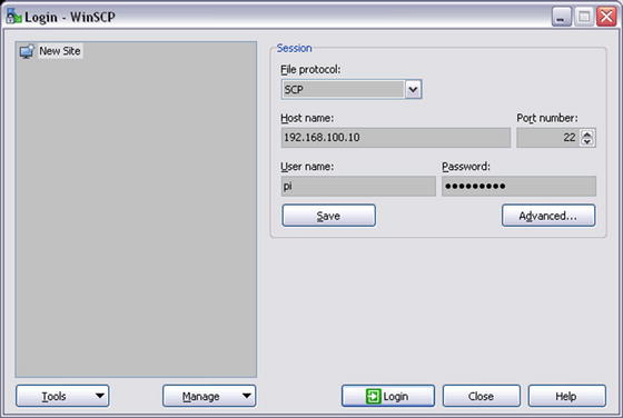
Figure 3-14. WinSCP login window
Click the File protocol: tab and select SCP. In the Host name: field type the IP of your Pi (not the IP you see in Figure 3-14). In the User name: field type pi, and in the Password: field type raspberry. Your session should look like Figure 3-14, except from the IP address. Hit Login and you’ll get connected to the Pi. Mind that you don’t need to log out from PuTTY to use WinSCP; you can be logged in from both programs simultaneously.
The first time you log in, you’ll get a warning window saying that, “The server’s host key was not found in the cache.” Click yes to log in. Figure 3-15 is a WinSCP connected to a Pi session. Don’t save this session yet, as you did with PuTTY, because we’re going to change the IP of the Pi later on.
On the left side, you have your computer directories, and on the right side, you have the Pi directories. Transferring files from one computer to another is super easy, as it’s done with a single drag and drop. Navigate to the Pd abstractions that deal with the communication with the Arduino, and drop these files to the arduino_abs directory on your Pi.
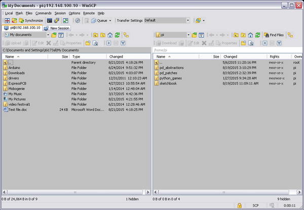
Figure 3-15. WinSCP connected to Raspberry Pi session
Changing the IP of the Pi
Up until now, we’ve used the Pi through a network router, but that’s not always very convenient. We’ll need to use the Internet sometimes, if we want to install software from the Raspbian repositories, but in general, when we want to work with the Pi, it’s best that it is connected straight to our computer, instead of the router. If we use the Pi as is, it will automatically get an IP using the DHCP protocol (this is the protocol used by your computer to get an IP when logging in to a network). We can use tools like Nmap to get the IP, but this is not very efficient, as we want to log in pretty fast and start developing our projects. The best solution to this is to set the Pi to have a static IP, which we’ll know. The way to set an IP address is via a file, which lies in /etc/network/ in the Pi. cd to that directory (by “cd” I mean to use the cd command to go to that directory) and type the following:
$ sudo nano interfaces
Don’t forget to use tab completion. Nano will open with the interfaces file content. We need to use sudo because we’re using the Pi as user pi, but we’re not in our home directory, so we need root privileges. Listing 3-1 shows what you should type in that file.
The “interfaces” file might have some more text in it, like “auto wlan0”, “allow-hotplug wlan0”, and so forth, but we don’t mind it. Line 6 in Listing 3-1, which begins with #, is a comment. Well, it’s not really a comment, but an executable line that has been commented out. By “commented out” I mean that we want this line to be there, but we don’t want it to be executed, so we turn it into a comment. Of course, in the actual file, the lines won’t be numbered, they’re numbered only here for convenience. All we really need to care about are lines 7 and 8. Line 7 defines that a static IP address will be set. Line 6, which is commented out, defines that an automatic IP address will be set, via the DHCP protocol, but since it’s commented out, it won’t actually do it. Line 8 sets a static IP address. The first two fields (192 and 168) are standard, so we’ll just use these. The last two fields are the ones we set manually. The third field, which is set to 100, is called the subgroup. This is a group without the network. We set it to 100, because usually DHCP sets small numbers like 1 and 2, so setting a high number will make it unlikely to get a clash with a DHCP address. The last field is the ID of the device. This can be anything between 1 and 254, but it must be unique within the subgroup. Don’t worry about lines 9 to 11, just use them as they show in Listing 3-1.
For these setting to take effect, we must reboot the Pi, but we must also change the IP of our computer, otherwise they won’t belong to the same subgroup, and they won’t be able to see each other and get connected. In your Pi’s terminal, type the following:
$ sudo reboot
Unplug it from your router (don’t unplug the power). On Windows, PuTTY might warn you that the “Server unexpectedly closed network connection,” but it’s of no importance; just close the window. The Pi will now reboot, and the new, static IP will be set. Connect the Pi to your computer via the Ethernet cable, and set a static IP to your computer. Your computer’s IP must have the first three fields the same as the Pi, and in the last field any number between 1 and 254, but not the same as the Pi, because this is the ID of the device, and the two devices must not have the same ID in the same subgroup (the third field is the subgroup). Each operating system has its own way to set a static IP, so we’ll cover them separately.
In your computer’s terminal, type the following:
$ ifconfig eth0
The output of this should be something like the following:
eth0      Link encap:Ethernet  HWaddr 08:00:27:e3:ef:78
          inet addr:10.0.2.15  Bcast:10.0.2.255  Mask:255.255.255.0
          inet6 addr: fe80::a00:27ff:fee3:ef78/64 Scope:Link
          UP BROADCAST RUNNING MULTICAST  MTU:1500  Metric:1
          RX packets:1120 errors:0 dropped:0 overruns:0 frame:0
          TX packets:852 errors:0 dropped:0 overruns:0 carrier:0
          collisions:0 txqueuelen:1000
          RX bytes:800971 (800.9 KB)  TX bytes:454335 (454.3 KB)
This is information about the Ethernet connection of your computer. The second line reads inet addr:10.0.2.15, which is the IP of the Ethernet connection of your computer (yours is very likely to be different). To change it, type the following (don’t forget to include sudo):
$ sudo ifconfig eth0 192.168.100.20
The last field can be any number between 1 and 254, but not the same with the Pi, which in Listing 3-1 is 10. Now type sudo ifconfig eth0 again and check the inet addr: field, and make sure that it includes the IP you just set. This technique changes the IP of your computer only for this session. As soon as you reboot it, the IP will again be set via DHCP. To set a permanent static IP you have to do what you did with your Pi, since that’s also a Linux system. Mind, though, to change only the Ethernet IP, not the Wi-Fi.
On OS X, you can set a static IP in a very similar way to Linux, or via the System Preferences. For the command-line version, in your computer’s terminal, type the following:
$ ifconfig en0
This will give you information about your Ethernet connection, which will look like this:
en0: flags=8863<UP,BROADCAST,SMART,RUNNING,SIMPLEX,MULTICAST> mtu 1500
        options=27<RXCSUM,TXCSUM,VLAN_MTU,TSO4>
        ether 00:25:00:a0:1a:b2
        inet6 fe80::225:ff:fea0:1ab2%en0 prefixlen 64 scopeid 0x4
        inet 169.254.15.79 netmask 0xffff0000 broadcast 169.254.255.255
        media: autoselect (100baseTX <full-duplex,flow-control>)
        status: active
What we care about is the fifth line, which reads inet 169.254.15.79. This is the IP set via DHCP (yours will probably be different). To change it, type (don’t forget to include sudo) the following:
$ sudo ifconfig en0 192.168.100.20
As with the Linux version, the first three fields must be the same with the Pi, but the last must be a number between 1 and 254, not the same with the Pi, which is 10 in Listing 3-1. Now type sudo ifconfig en0 again and check the line of the IP, to make sure that it’s the one you’ve set.
Instead of the terminal, you can also use System Preferences. Go to Applications ![]() System Preferences, and click Network, in the Internet and Wireless section. Figure 3-16 shows the Network window of OS X’s System Preferences. Click the Configure IPv4 tab and select Manually. This will enable you to type in the following three fields: IP address, Subnet Mask, and Router. In the IP address field type the static IP for your computer, which should be 192.168.100.x, where x must be between 1 and 254, but not the same as the Pi’s, which is 10. In the Subnet Mask field, type 255.255.255.0, and leave the Router field blank. The Apply button on bottom right of the window will have become clickable, so when you type the two addresses, click it. Now your computer has a static IP for Ethernet connections. Using the System Preferences will make this IP permanent, whereas using the terminal will only change the IP for the current session, and as soon as you reboot your computer, the IP will be set via DHCP again. There are ways to set a permanent IP apart from using the System Preferences, but they are a bit complicated, and since the System Preferences allow us to do this so easily, we won’t deal with that here.
System Preferences, and click Network, in the Internet and Wireless section. Figure 3-16 shows the Network window of OS X’s System Preferences. Click the Configure IPv4 tab and select Manually. This will enable you to type in the following three fields: IP address, Subnet Mask, and Router. In the IP address field type the static IP for your computer, which should be 192.168.100.x, where x must be between 1 and 254, but not the same as the Pi’s, which is 10. In the Subnet Mask field, type 255.255.255.0, and leave the Router field blank. The Apply button on bottom right of the window will have become clickable, so when you type the two addresses, click it. Now your computer has a static IP for Ethernet connections. Using the System Preferences will make this IP permanent, whereas using the terminal will only change the IP for the current session, and as soon as you reboot your computer, the IP will be set via DHCP again. There are ways to set a permanent IP apart from using the System Preferences, but they are a bit complicated, and since the System Preferences allow us to do this so easily, we won’t deal with that here.
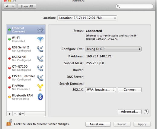
Figure 3-16. Network preferences on OS X
Setting a Static IP on Windows
The description here applies to Windows XP, but other Windows versions should be rather similar. Go to Control Panel ![]() Network Connections
Network Connections ![]() Local Area Connections, click Properties. In the Properties window, select Internet Protocol (TCP/IP) and click Properties again. The window shown in Figure 3-17 will open. The Obtain IP automatically option will be chosen by default. Click Use the following IP address and the fields that follow will become editable.
Local Area Connections, click Properties. In the Properties window, select Internet Protocol (TCP/IP) and click Properties again. The window shown in Figure 3-17 will open. The Obtain IP automatically option will be chosen by default. Click Use the following IP address and the fields that follow will become editable.
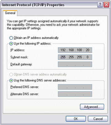
Figure 3-17. IP set window on Windows XP
In the IP field, type your IP , which should be 192.168.100.x, where x must be between 1 and 254, but not the same as the Pi’s last field of its IP, which is 10. In the Subnet mask: field type 255.255.255.0 and leave the rest blank. Click OK and the new, static IP will be set.
Log in to the Pi Without a Router
Now that both the Pi and your computer have a static IP and they are both in the same subgroup, you can connect to the Pi straight from your computer, without using your Internet router. Your Pi should already be connected to your computer’s Ethernet, so go ahead and connect to it like you did before, only this time type the new IP where required. On Linux and OS X, in a terminal, type the following:
$ ssh -X [email protected]
Then on Windows launch PuTTY (I assume that your X server is still running), put the new IP in the Host Name (or IP address) field, and click Open. If you are refused the connection for a few times when you try to reconnect, wait a bit as the Pi might be still booting. If you continue to get refused, insist a bit and eventually you’ll be asked for Pi’s password. If all goes well you should be logged in your Pi like before, only now the Pi has no Internet connection.
Whenever you want to connect the Pi to the Internet (to install software with apt-get, for example), you’ll need to modify the /etc/network/interfaces file, shown in Listing 3-1. All you need to do is remove the comment sign from line 6 and comment out lines 7 to 11 (put a # at the beginning of each line). Then you’ll need to find the IP of the Pi, as you did in the beginning (log in to your router, or use Nmap, for example) and log in with that IP. When your Internet session is done, go back to /etc/network/interfaces and do the reverse, comment out line 6, and remove the comment sign from lines 7 to 11, and reboot the Pi. For the use of the Pi in this book, we won’t need any Internet, so it’s best if you always reset the static IP whenever you log in the Internet.
Save Login Sessions on Windows
Since your Pi now has a static IP, you might want to save this session, so you don’t need to type the static IP every time you want to log in the Pi. In PuTTY, in the Saved Sessions field, type the name of the session, which could be raspberry, and click Save. To test that the session has been saved, close PuTTY and open it again. Underneath the Saved Sessions field, you’ll find the space where your saved sessions are. raspberry should be in there—click it and then click Load. The static IP of the Pi should appear in the Host Name (or IP address) field. Click Open and log in to the Pi.
You might also want to save the Pi session to WinSCP, to make things a bit faster. Launch WinSCP and type the new IP along with the rest of the data, the same way you did before. Now click Save and the Save session window will open, shown in Figure 3-18. It recommends that you not save the password, but you can do as you like. It can also create a desktop shortcut, which you might want if you work a lot with the Pi. If you have a shortcut of WinSCP however, it’s still fast enough. Click OK and relaunch WinSCP to make sure your session has been saved. It will appear on the right side of the login window, shown back in Figure 3-14 (this figure doesn’t include the saved session, because we hadn’t saved it when we first used WinSCP), and is probable already selected. The Pi’s data will appear in the login window (except from the password, if you didn’t save it). Lastly, log in to test if all goes well.
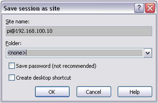
Figure 3-18. WinSCP “Save session” window
Shutting Down the Pi
Like all computers, the Pi needs to be shut down via a command (clicking buttons is the same: it generates commands), and not only by powering it off. To shut it down properly you must type the following in the Pi terminal:
$ sudo poweroff
You’ll get a message in your computer’s terminal saying that the connection is now closed (maybe not on Windows). To reboot it, unplug the power cable and plug it back in and log in as before. Note that on other embedded computers the command might be sudo halt instead. What we’ll do now is write a script to shut the Pi down, because we will need this when we” be using the Pi without a screen and keyboard. cd to /etc, create a new directory called my_scripts, and cd to that. To do this, type the following:
$ cd /etc
$ sudo mkdir my_scripts
$ cd my_scripts
You’ll need sudo only for the command that creates the new directory. Now we’re in the new directory, where we’ll write our script to shut the Pi down. We’ll use nano to edit the script and afterward one command to make it executable. Type the following:
$ sudo nano shut_down.sh
We need sudo because we’re not in the home directory, and we’re not root. The .sh extension is the extension for shell scripts. In nano, type the following:
sudo poweroff
Hit Ctrl+O and Return, to write the text to the file, and then Ctrl+X to exit nano. To test if it’s working, go back to your home directory and type the following:
$ cd ~
$ sh /etc/my_scripts/shut_down.sh
This will properly shut down the Pi . You might be wondering what the point of this is since you can just type sudo halt to shut down the Pi. When we’re building projects using the Pi headless, we won’t have the ability to type anything to the Pi’s terminal, so we need to have a way to quit all programs and run sudo halt so that the Pi can shut down properly. Now go back to edit the script. From your home directory, type the following:
$ sudo nano /etc/my_scripts/shut_down.sh
In nano, type the following:
sudo killall pd
sleep 3
sudo poweroff
The last line was already there; you just need to type the other two lines above it. The first line will quit Pd (we assume that we’ll be running Pd), then the Pi will wait for three seconds (with “sleep 3”), and eventually the halt command will run. Save it (Ctrl+O and Return) and exit nano. Now launch Pd and open a new window. Figure 3-19 shows the patch you should build. [shell] from the “ggee” library enables us to talk to the shell, therefore to run scripts, apart from other things. Since we’ve already wrote our script, all we need to do is call it, the same way we would call it from a terminal. Save the patch (I’ve named it shut_down), lock it and click the message. Pd will quit, and the Pi will shut down.
This is a very helpful feature, since we can use the Arduino to run this script and shut down the Pi properly, even if there’s no keyboard or screen attached to it. Don’t try yet to use the patch in Figure 3-19 with the Arduino, because it’s very likely to cause a crash, since the Arduino will be sending its data at the specified baud rate, so this message will be called several times. We’ll see in some of this book’s projects how to implement this in a patch.
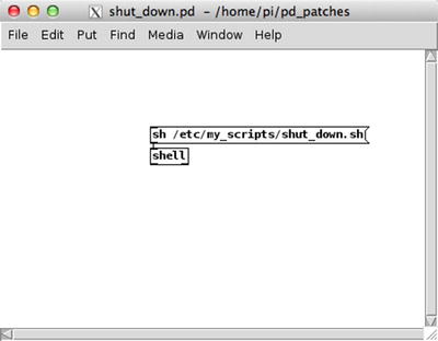
Figure 3-19. Pd patch to shut the Pi down
This concludes our Pi overview. It is a very useful tool that we’ll use in some of this book’s projects. Hopefully it will be useful to you in more projects that you build yourself. Now let’s see how we can use the Arduino wirelessly.
There will be some occasions where we’ll rather use the Arduino wirelessly. This can be the case when building an interface for a performer that doesn’t want to have cables hanging out of him/her. Being able to receive and send data between the Arduino and Pd wirelessly, expands the possibilities of interfaces a lot, so we’ll go through that in this section. To have wireless communication, we’ll need some more equipment. There are various options, depending on the actual interface we want to build. Here we’ll cover the two most popular, the Bluetooth, and the very popular XBee.
Bluetooth vs. XBee
The Bluetooth solution is the cheaper of the two. The Bluetooth modules used with the Arduino are just that, Bluetooth modules, which can communicate with the computer if the computer’s Bluetooth is activated. Then we can see it in our serial ports list and use the Arduino as we do with a USB cable. All you need to use Bluetooth with the Arduino is a Bluetooth module. Then you can immediately send and receive data between your computer and the Arduino.
XBee is a radio transmitter/receiver (also called a transceiver) produced by Digi International, which can be configured in any of the three OSes (Linux, OS X, Windows), and replaces the USB cable we’ve been using so far. The XBee is a more expensive solution. First of all, you’ll need at least two XBees: one connected to the Arduino and another one connected to your computer. Apart from that, you’ll also need some breakout boards to be able to configure them. The XBee has a non-breadboard friendly design so you can’t build a circuit on a breadboard/perforated board to use it, you’ll need to buy special breakout boards (called XBee Explorer) to make your life easier. If you want to use the XBee with an Arduino Uno, you’ll also need a shield to mount on top of the Arduino, on which you’ll mount the XBee so it can act like a transmitter/receiver for the Arduino. If you want to use it with another kind of Arduino (the Pro Mini, for example), you’ll need another kind of XBee Explorer for that.
All this might sound a bit expensive, but with a moderate budget, you can build a very flexible and powerful interface. The XBee has some advantages compared to the Bluetooth. First, it has a greater range than the Bluetooth, which might be very useful in a case of a concert where the performer is on stage and the computer is next to the mixing console (there can always be reasons for such a setup). In this case, the Bluetooth might not be able to cope with the demands of the setup. Other occasions are very likely to prove the XBee a more suitable solution, compared to the Bluetooth. Another advantage is that with the XBee, you can build more complex networks, like start networks (where many XBees communicate with a central XBee), mesh networks (where all XBees cooperate in the data distribution), and others. These are beyond the scope of this book, so I’m not going to cover them here; they’re mentioned only as general information. Figures 3-20 and 3-21 show a Bluetooth module and an XBee transceiver respectively.
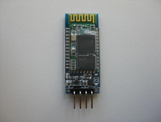
Figure 3-20. HC-06 Bluetooth module
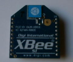
Figure 3-21. XBee series 1 with trace antenna
Using a Bluetooth Module with Arduino
We’ll use the HC-06 Bluetooth module to communicate with the Arduino. This is an inexpensive module that works out of the box. The only thing you need is a breadboard and some jumper wires. We’ll first use it with its default settings, and then we’ll configure it to change some things, like its name, its baud rate, and its passcode pin. Most likely this module comes with headers (the pins on its bottom in Figure 3-20) soldered on its communication pins, so you don’t need to do it yourself. If there’re no headers soldered, you should use angled male headers and solder them yourself. The pins we’re going to use are VCC, GND, TXD, and RXD, which are indicated in the back side of the module.Go ahead and upload serial_print.ino sketch found in the GitHub page of the Pd abstractions [serial_print] and [serial_write]. Make the appropriate circuit (the three potentiometers and three switches circuit from Chapter 2). Once you do that, unplug the USB of the Arduino and make the following connections with it and the Bluetooth module:
HC-06 VCC connects to Arduino 5V.
HC-06 GND connects to Arduino GND.
HC-06 TXD connects to Arduino Rx (digital pin 0).
HC-06 RXD connects to Arduino Tx (digital pin 1).
We see here that we’re using the first two digital pins of the Arduino, which we haven’t used before. Chapter 2 mentioned that these pins are used for serial communication. Since we’ll communicate serially with the Arduino via the Bluetooth module, we have to use these pins for this reason. Tx (or TXD) is the transfer pin, and Rx (or RXD) is the receive pin. So the transfer pin of the Bluetooth module should connect to Arduino’s receive pin, and the receive pin of the Bluetooth module should connect to Arduino’s transfer pin, so that whatever the Bluetooth module transfers is received by the Arduino, and the other way round. You can use the USB to power up the Arduino, or an external power supply, like a 9V battery (the external battery is preferable because there’s no physical connection between the Arduino and the computer, so we can clearly see how the Bluetooth module works wirelessly). Figure 3-28 shows a battery connected to the Arduino with the XBee shield mounted on top of it. Connect the positive pole of the battery to the VIN pin of the Arduino (the first pin of the header next to the analog pins header), and its negative pole to the GND pin of the Arduino, which is right next to the VIN pin. With the Bluetooth module you just don’t have the XBee shield on top as in Figure 3-28, so just connect the battery poles to the corresponding pins of the Arduino.
When you power up the Arduino you should see the a red LED blinking, on the Bluetooth module. This means that it is powered, but it’s not connected to any device yet. You must first pair your computer with the Bluetooth, like you would pair it with any Bluetooth device (every OS has its own Bluetooth parity tool, but I’m not going to cover that here). If you’re asked for a passcode key, use 1234. When you pair it, the red LED on the Bluetooth module will stop blinking and will stay lit. Open the help patch of the [serial_print] Pd abstraction and click the “devices” message. You’ll get the available serial ports on Pd’s console, and the Bluetooth module should be there. It will appear under the name /dev/tty.HC-06-DevB, where /dev/tty. might differ, according to your OS. If [comport] has already connected to another port, click the “close” message and then type the Bluetooth port number on the number atom connected to the “open $1” message. If all goes well, you should see the values of the potentiometers and the switches in the Pd patch.
Mind that we used the serial_print.ino sketch because it runs on a 9600 baud rate. If you have changed the baud rate of the sketch, it won’t work, so set it back to 9600 and try again. This is because that’s the default baud rate of the Bluetooth module. There might be some cases where we’ll need another baud rate, so we’ll have to configure the module for that. To do that we’ll need to connect to it serially and type some AT commands (AT commands are commands for embedded computers). These commands are pretty easy, and we could use them with any terminal emulator program, like CoolTerm, or PuTTY. There is a drawback with HC-06, though. Commands don’t get through with the newline feed (hitting Return), but the device waits for one second once you start typing. When that second is over, it will check its input buffer and use whatever is there. If a command is not full, it will just ignore it. This means that we need to type quite fast, and this can prove to be quite difficult. There is a work around to that issue, using the Arduino itself to configure the Bluetooth module.
Close the Bluetooth port of your computer, and unplug the Arduino. Disconnect the jumper wires from the potentiometer/switch circuit and make the following connections:
HC-06 VCC -> Arduino 5V
HC-06 GND -> Arduino GVD
HC-06 TXD -> Arduino D10 (digital pin 10)
HC-06 RXD -> Arduino D11 (digital pin 11)
Listing 3-2 shows code I found in a post on plasticbots.com, which I have slightly modified to fit the needs of this chapter. Write it in a new sketch window in the Arduino IDE.
Line 1 imports the SoftwareSerial library, which enables us to connect serially to other devices, while leaving the default Arduino serial pins, digital pins 0 and 1, free. This way we’re able to upload code to the Arduino board, communicate with it via the IDE’s serial monitor, and at the same time connect to the Bluetooth module. Line 5 defines an instance of the SoftwareSerial library, called bt_serial, which stands for Bluetooth Serial. An instance of a class is called an object, so bt_serial is considered an object of the SoftwareSerial class. This approach to programming helps us use functions and other data of a given class in a different way for each instance of the class. For example, if we defined two objects of the SoftwareSerial class, bt_serial1 and bt_serial2, we could use different pins for each, like 10 and 11 for bt_serial1, and 8 and 9 for bt_serial2. It’s not really important to grasp the concept of objects in programming, this information is provided only for those interested.
Line 9 begins the serial communication between the computer and Arduino, using the Serial class, and line 12 begins the serial communication between the Arduino and the Bluetooth module, using the SoftwareSerial class, via the bt_serial object. Don’t mind the commented lines for now, I’ll explain them in a bit. Line 17 sends the AT command, which does nothing really, it only returns an OK if we’re connected to the module. Note that all commands are sent with print and not with println, because we don’t want to send the newline character.
Line 21 send the AT+VERSION command, which returns the firmware version of the module. It’s not really necessary here, but it’s provided just for the information. Line 24 sends the AT+PINxxxx, where x is a number, and it’s used to change the passcode pin of the module. Again, you don’t really need this, but you might want to change the default pin.
Line 27 sends the AT+NAME command, which is used to change the name of the module. Like with the AT+PIN command, there’s no space between the command and its argument (the name you want to set to your module). This is a helpful command since you might want to use more than one module at the same time, and naming them will make things a bit easier, as it will be much simpler to tell which serial port communicates with which module. In this case, we’re renaming it myBTmodule.
Finally, line 31 changes the baud rate of the module to 57600. The available baud rates are shown in Listing 3-3.
All the delays after each command are there to make sure that the module will have enough time to receive the commands and make the appropriate configurations. When you upload this code to your Arduino, open the serial monitor from the Arduino IDE. The first thing that will be printed is “Set up HC-06 Bluetooth module!” and then you’ll receive the replies to each command from the module, which will be printed in the same line. Make sure you set the correct baud rate to the serial monitor. If you get the following line in the serial monitor, all will be fine:
OKOKfirmwareversionOKsetpinOKsetnameOKsetbaud
“firmwareversion” will be replaced by the firmware version of your Bluetooth module, of course. Now I’ll explain what the commented lines do. We’ve now changed the baud rate of the module, if we want to reconnect to it, we must make sure we use the correct baud rate for both the Arduino and the Bluetooth module. Our baud rate is now 57600, so if you want to run this sketch again, you have to comment out lines 9 and 12, and remove the comment sign from line 10 and 13. This will start the serial communication between the computer and the Arduino, and between the Arduino and the Bluetooth module at the correct baud rate. The rest of the commands depend on what you want to do whenever you upload this code to the Arduino. The AT and AT+VERSION commands are not so important, but the commands on lines 24, 27, and 31 are.
If you want to set a different passcode pin to your module, set that in line 24, to change the name set it in line 27, and to change the baud rate do it in line 31. The 9600 baud is there in line 30 and it’s commented out. If you want to set another baud rate, use the numbers from Listing 3-3. Note that if you want to configure another module, which hasn’t been configured yet, you should use the begin functions in lines 9 and 12 (exactly like they are in Listing 3-2), and not the ones in lines 10 and 13, because this Bluetooth modules if configured to a 9600 baud by default.
Using this sketch enables us to easily configure the HC-06, since we don’t need to type its commands in real time, and stress ourselves with the timing issue. Save it with a name that helps you understand what it does, so you can use it in the future.
Now unplug the Arduino and again build the potentiometer and switch circuit, and disconnect the Bluetooth module. Connect the Arduino to your computer and upload the serial_write.ino sketch to it (this sketch uses a 57600 baud rate). Unplug the Arduino and connect the Bluetooth module like you did with the serial_print.ino sketch, where the TXD pin of the module goes to the Rx pin of the Arduino (digital pin 0), and the RXD pin of the module goes to the Tx pin of the Arduino (digital pin 1). Power up the Arduino (again it’s better to use an external battery), open your computer’s Bluetooth and pair it to the Bluetooth module, which will now appear as myBTmodule. Now open the help patch of the [serial_write] abstraction and check the serial port number of the Bluetooth module. The port will be now called something like /dev/tty.myBTmodule-DevB (on OS X, replace /dev/tty. with your OS’s port name). Open the port and you should get the values of the potentiometers and the switches. Congratulations, you’re now free of wires!
Using the XBee with Arduino
To use the XBee, we’ll use an XBee Arduino shield (shown in Figure 3-22) and an XBee Explorer USB (shown in Figure 3-23). Make sure that you’ve mounted the XBee on the Explorer properly, otherwise you could damage it. There are two lines on the Explorer and the shield indicating how the device must be mounted, by outlining the shape of the XBee. Figure 3-24 shows that. XBee has its own software called X-CTU, which runs on Windows only. This software provides a lot of features that we won’t really need, but luckily there is free software for all three operating systems, which we can use to configure the XBee. On Linux and OS X, we can use the same software, CoolTerm (http://freeware.the-meiers.org/) to configure them. On Windows, we’re going to use PuTTY to do this. There is also Minicom for all three platforms (on Windows it’s available through Cygwin) and other solutions, but we’re not going to use any of it here.
Connecting to the XBee from Linux and OS X
To connect wirelessly with an XBee (actually two XBees) we’ll need an XBee shield, like the one shown in Figure 3-22, and an XBee Explorer USB, like the one in Figure 3-23. Launch CoolTerm with the XBee Explorer USB connected to your computer. In CoolTerm go to Connections ![]() Options. . . (or click the Options icon on top of the window) and the window in Figure 3-25 will open.
Options. . . (or click the Options icon on top of the window) and the window in Figure 3-25 will open.
On the left side, Serial Port is chosen, which is what we want. Click the Port: tab to select the serial port of the XBee. This should be something like “usbserial-xxxxx” where x is either a letter or a number. The Baud rate: will be at 9600 by default, which is what we want for now, because the XBee is configured at this baud rate by default. Leave the rest of the fields as they are. Click Terminal on the left side menu. In Terminal, make sure the Local echo tick box is selected, otherwise what you type in the CoolTerm window won’t appear on screen—much like when typing passwords in a Unix terminal, and this is not very convenient. Click OK and you’ll be back to the CoolTerm session. On top of the window, click the Connect icon to get connected to the XBee.
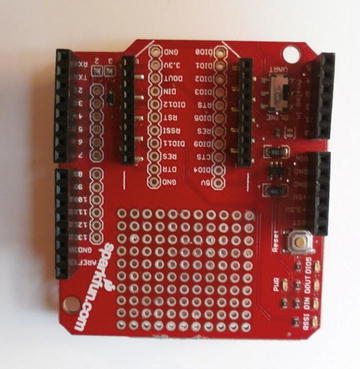
Figure 3-22. XBee Arduino shield
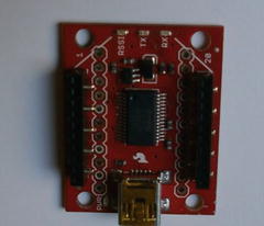
Figure 3-23. XBee Explorer USB
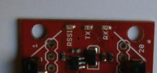
Figure 3-24. XBee Explorer indication for proper mounting
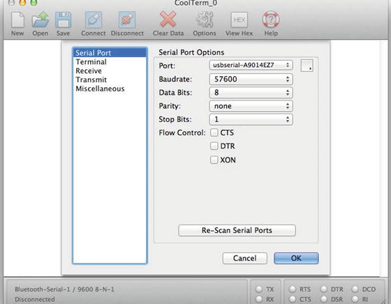
Figure 3-25. CoolTerm’s connections options window
Connecting to the XBee from Windows
We’ll use PuTTY to configure the XBee. First, check which serial port your XBee is at. On Windows XP, click Start, right-click My Computer and click Properties. On the Properties window click the Hardware tab and there click the Device Manager button. In the Device Manager, you’ll find the serial port of the XBee under Ports, which should be a USB Serial Port, referred to as COMx, where x is a number. On other Windows versions, the procedure should be similar. If you don’t get a port number, you might need to install drivers for the XBee. A simple online search should give sufficient results for this.
Now launch PuTTY, but instead of an SSH session, choose Serial, as shown in Figure 3-26. In the Serial line field, type the port name of the XBee. The Speed should be set to 9600, which is the default baud rate of PuTTY, but also the baud rate the XBees have by default. Before opening the connection, click Terminal on the left side menu, and under Local echo, make sure you tick on Force on, as shown in Figure 3-27. This will enable displaying whatever you write on PuTTY’s terminal as you’re configuring the XBee. If it’s left un-ticked, then you won’t be seeing what you type, which is not very convenient. Now click Open and PuTTY’s terminal window will open, where you can start configuring your XBee.
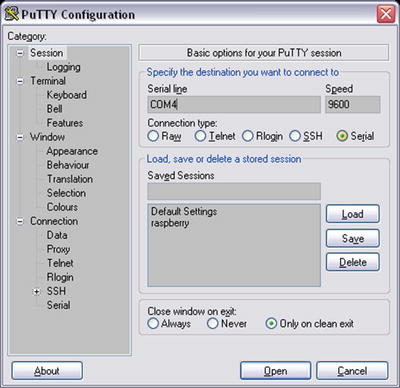
Figure 3-26. PuTTY Serial session
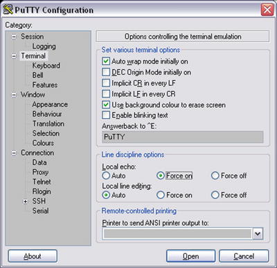
Figure 3-27. Enabling Local echo in PuTTY’s terminal
Now that we’re connected to the XBee, we’re ready to type some commands to configure it. The following steps are common for all three OSes. I’ll first show the commands and then explain what each does. Once you’re connected and you start typing in the CoolTerm or PuTTY window. Type the following:
+++
Don’t hit Return after this command, only wait until you receive an OK from the XBee. Once you receive the OK, go ahead and type the rest, now hitting Return with every command. Mind that once you get the OK you have about 30 seconds to type each command, so don’t take your time doing it, otherwise the commands won’t go through. You can tell that a command was set successfully by the OK respond from the XBee. If you don’t get it, you must type the three plus signs again and start the whole configuration (not connection) procedure from the beginning. Listing 3-4 shows the rest of the commands. On PuTTY, all commands will appear on the same line, which is a bit confusing.
Again we’re using AT commands (this time with no plus sign), so we’ll use only the last two letters to refer to them. ID is the PAN (personal area network) ID, used to broadcast messages to a certain network. The value for the PAN ID is 16-bit, so you can have any number in the range 0-0xFFFF. If you want to broadcast messages to all PANs, use 0xFFFF, otherwise the XBee will broadcast its messages only to the set PAN. We used a decimal value here (1234), but hexadecimal values are also valid (using the 0x prefix).
The MY command is the source address. Again, this is a 16-bit value in the range 0-0xFFFF. This is the address that the XBee will listen to. In our case, it’s 1, but you could use anything in the 16-bit range, except from 0xFFFF. The DL command is the destination address (in fact, it’s Destination Address Low). This is the address that the XBee will transmit to. This command reads the lower 32 bits of a 64-bit address, but we can use it with 16-bit values only, again in the range 0-0xFFFF, excluding 0xFFFF. BD is the baud rate command. Listing 3-5 shows the available baud rates.
Here we have used the 57600 baud rate, since we provided number 6 to the command. Changing the baud rate of the XBee is not really necessary, but we do it to know how to, since it will very probably be necessary in some cases. The last command, WR, is the write command. If you exclude it, anything you’ve set will be discarded. With the WR command, all the data you’ve sent to the XBee will be stored even when the XBee is powered off, so you can use it in a plug-and-play mode.
Now that we’ve configured the first XBee, let’s configure the second one too. The steps are identical up to writing the commands. On Linux and OS X, hit the Disconnect icon in CoolTerm first, and unplug the Explorer USB. On Windows, you can leave the PuTTY window open and unplug the USB. Mount the second XBee on the Explorer and plug it in. On Linux and OS X, click the Connect icon. On Windows, right-click the title bar of the PuTTY window and click Restart Session. We’re now ready to configure the second XBee. The commands are essentially the same, only the MY and DL commands get reversed arguments. Listing 3-6 shows the commands for the second XBee.
Again, don’t hit Return when you type the first command (+++), and wait for the OK. After entering each of the rest of the commands, hit Return and again wait for the OK, to type the next command. When you receive the OK after the last command (WR), on Linux and OS X, click the Disconnect icon on top of the window. On Windows, just close the PuTTY window, and you’re done.
The ID command takes the same argument so the two XBees are in the same network. As you see MY now got 2, and DL got 1, so the two XBees can talk to each other. The BD must definitely get the same argument, otherwise the XBees won’t be able to communicate. Finally, WR will write the changes so they can take effect. The full command list for the XBee is available on the Internet, if you’re interested in more configuration options. The ones here will be enough for us to use the Arduino wirelessly, however. Make sure you don’t forget the baud rate of the XBee in case you want to reconfigure it in the future. Trying to log in the XBee with a 9600 baud rate won’t work because it is now configured at a 57600 baud rate, and the computer won’t be able to talk to the XBee.
Now it’s time to test the two XBees. We can use the serial_write.ino Arduino sketch that from the GitHub page with the Pd abstractions. We’ll use that because we’ve already configured the XBees to a 57600 baud rate, and the serial_write.ino sketch uses this baud rate. Apart from both XBees needing to have the same baud rate to communicate with each other, the Arduino must have the same baud rate as well, so that it can transmit its data via the XBee. Mount the XBee shield on top of the Arduino, an XBee on the XBee headers on the shield, and build the circuit with the three potentiometers and the three switches. To upload the sketch to your Arduino board you need to use a switch on the XBee shield, which is next to the XBee headers. This switch has two positions, DLINE and UART. To program the Arduino set it to DLINE and connect the Arduino to your computer via USB. Once you’ve programmed it, you can unplug it to power up it with a battery so you can clearly see the wireless connection is action (you can use the USB cable as well). Turn the XBee shield switch to the UART position, so you can use the XBee. Then connect the batter the same way you did with the Bluetooth module. Figure 3-28 shows the battery connections. Once you power it up you should see both the Arduino and the XBee turning on. Mount the other XBee on the XBee Explorer and connect it to your computer with a USB cable. The XBee is simultaneously a transmitter and a receiver, so it’s not important which XBee will be connected to the Arduino and which will be connected to the computer.
Now open the help patch of the [serial_write] abstraction and click the “devices” message to see the available serial devices. Look for the serial port of the XBee, and type its number to the number atom connected to the “open $1” message. The serial port of the XBee will open and you should start seeing the values of the potentiometers and the switches in the Pd patch. Congratulations! You’ve gone wireless once again!
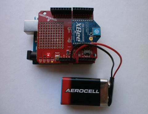
Figure 3-28. Powering up the Arduino with a 9V battery
Conclusion
This chapter covered the use of the Raspberry Pi (most of which applies to other embedded computers as well) and how to use the Arduino wirelessly. This concludes all introductions needed for this book. In some of the projects that will be developed here, we’ll use either an embedded computer or a wireless connection to the Arduino, so this chapter is very important to realize these projects.
Apart from the interfaces built here, being able to use embedded computers and wireless connections, enables you to realize lots of very flexible and powerful projects. Embedded computers are very useful when building mobile projects where there’s no need to look at a computer screen, so the computer can be hidden inside the project enclosure. You can build custom-made, very flexible interfaces that exactly fit your needs. Wireless communication between the computer and the Arduino can prove to be very helpful when cabling can make a setup problematic, and a cable-free setup seems more appropriate.
A subject we haven’t covered here is the use of external sound cards with embedded computers. When using computer audio, it’s generally advisable to use an external sound card, because the computer’s sound card circuit is usually not very good. This is because computers tend to be rather compact, and since they are general purpose devices, they’re not dedicated to audio, so their audio circuit is not of the highest priority, resulting in quality reduce. An external sound card is dedicated to audio, so the quality of the audio output is number one priority, making it more appropriate for making music. Also, an external sound card usually provides input channels, whereas the Raspberry Pi does not. Some sound cards provide more than two input/output channels, which might be desirable, plus most sound cards provide pre-amps for input and output, which helps the audio overall amplification. The Raspberry Pi has dedicated sound cards, because it’s a very popular computer with a big community. These sound cards usually come with OS images including the necessary drivers so that the sound card can work.
In case you want to use another sound card, or in case you’re using another embedded computer, you’ll have to find another solution (if you want to use an external sound card). There is an issue here because most of the sound cards don’t include drivers for Linux. In general, Linux is outside the commercial market, so sound card designers usually don’t bother to build drivers for it. Sound card drivers for Linux depend on the Linux developers. If you’re planning on buying a sound card for your embedded computer, do a thorough research first. Search the Internet for sound cards that are reported to work with your embedded computer, check forums, and ask around. A general rule is that a class-compliant USB sound card (which will most probably not need drivers for OS X, which, like Linux, is Unix-based) is very likely to work with Linux. If it doesn’t work (or doesn’t work properly) with the default settings of Pd, try to use it with the Jack audio server (we’ll cover it in the first project that uses an embedded computer). There is a great possibility that Jack will work better with a sound card than another audio server.
Now that we have acquired all necessary background, we can start building musical projects. In the next chapter, we’ll build some very simple interfaces, to start getting the hang of it. They won’t be finalized interfaces and they will be rather limited. They will be the kickoff for building more complex, expressive tools to make music.