In this chapter, we look at using serial communication protocols. The most ubiquitous of these are USART, SPI, and I2C, which I will be explaining in this chapter. This is one chapter you do not want to skip, as we cover using sensors, GPS, GSM, and a host of other things. So, grab a bottle of water and sit down. This will be a long one.
Using USART (Universal Synchronous Asynchronous Receiver Transmitter)
The Universal Synchronous Asynchronous Receiver Transmitter (USART) is my favorite communication protocol. The reason it is my favorite is because it is the simplest to use. It is possible for an embedded systems designer to understand every detail of the USART protocol. Sometimes you may see USART being written as just “UART”. For our applications, they do pretty much the same thing. USART is just an enhanced UART protocol, as the missing “S” (synchronous) requires clocking to be synchronous and adds a little complexity to your design. Therefore, we will use the USART module asynchronously in compliance with KISS.
The USART module onboard the PIC® microcontroller can be used synchronously or asynchronously. When used asynchronously, all the communication takes place without a clock. This saves an I/O pin as in this mode only the transmit and receiver lines are required. The asynchronous mode is the type of communication we will use. Synchronous mode allows the module to be used with a clock and is not as widely used, thus we will not discuss it in this book.
An important consideration for USART is the baud rate. The baud rate of the USART specifies the rate at which the USART transfers data. A baud rate of 2400 means that the USART can transfer a maximum of 2400 bits per second.
Serial Character LCD
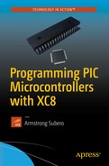
We begin our usage of USART by sending signals to a serial LCD module. The serial LCD module we will use is the Parallax 2x16 LCD (see Figure 9-1). In this example, we write text and commands to the LCD. The Parallax datasheet provides information about the commands that must be sent to the LCD.
This LCD module has selectable baud rates of 2400, 9600, and 19200. This LCD also includes a built-in piezo speaker and has a backlight.
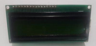
Figure 9-1 Parallax serial LCD
Let’s take a look at the code for setting up the USART module (see Listing 9-1). We first create a header file that contains several function prototypes. After you run the code in this section, download the datasheet from Parallax for the LCD and experiment using the built-in piezo speaker. I guarantee that you will be using USART like a pro in no time.
In addition, I have deliberately left out schematics for interfacing these modules so that you will download the datasheets and find out how they work. All these modules require connecting four wires to them to get them to work and the serial LCD requires connecting three. Come on, you’re smart—you can figure it out!
There is one trap for beginners with USART. The TX line is connected to RX and the RX line is connected to TX.
Listing 9-1 EUSART Header
/** File: EUSART.h* Author: Armstrong Subero* PIC: 16F1717 w/X OSC @ 16MHz, 5v* Program: Header file to setup PIC16F1717* Compiler: XC8 (v1.35, MPLAX X v3.10)* Program Version 1.0** Program Description: This header sets up the EUSART module* Created on November 7th, 2016, 7:00 PM*//*************************************************************** Function Prototype**************************************************************/char EUSART_Initialize(const long int baudrate);uint8_t EUSART_Read(void);char EUSART_Read_Char(char *output);void EUSART_Write(uint8_t txData);void EUSART_Write_Text(char *text);void EUSART_Read_Text(char *Output, unsigned int length);
Then we create the source file that implements these functions, as shown in Listing 9-2.
Listing 9-2 EUSART Source
/** File: EUSART.c* Author: Armstrong Subero* PIC: 16F1717 w/Int OSC @ 16MHz, 5v* Program: Library file containing functions for the EUSART module* Compiler: XC8 (v1.38, MPLAX X v3.40)* Program Version: 1.1* *Added additional comments** Program Description: This Library allows you to use the EUSART module of the* PIC16F1717** Created on November 7th, 2016, 7:10 PM*//**************************************************************Includes and defines*************************************************************/#include "16F1717_Internal.h"#include "EUSART.h"/*************************************************************** Function: char EUSART_Initialize (const long int baudrate)** Returns: Nothing** Description: Initializes the EUSART module** Usage: EUSART_Initialize()*************************************************************/char EUSART_Initialize(const long int baudrate){unsigned int x;x = (_XTAL_FREQ - baudrate*64)/(baudrate*64);if(x>255){x = (_XTAL_FREQ - baudrate*16)/(baudrate*16);BRGH = 1;}if(x<256){SPBRG = x;SYNC = 0;SPEN = 1;TRISC7 = 1;TRISC6 = 1;CREN = 1;TXEN = 1;return 1;}return 0;}/*************************************************************** Function: char EUSART_Read (void)** Returns: Nothing** Description: Reads the EUSART module** Usage: EUSART_Read()*************************************************************/uint8_t EUSART_Read(void){RC1STAbits.SREN = 1;while(!PIR1bits.RCIF){}if(1 == RC1STAbits.OERR){// EUSART error – restartRC1STAbits.SPEN = 0;RC1STAbits.SPEN = 1;}return RC1REG;}// Read Charchar EUSART_Read_Char(char *Output){Output = EUSART_Read();return Output;}/*************************************************************** Function: char EUSART_Write (uint8_t txData)** Returns: Nothing** Description: Writes to the EUSART module** Usage: EUSART_Write(x)*************************************************************/void EUSART_Write(uint8_t txData){while(0 == PIR1bits.TXIF){}TX1REG = txData; // Write the data byte to the USART.}void EUSART_Read_Text(char *Output, unsigned int length){int i;for(int i=0;i<length;i++)Output[i] = EUSART_Read();}/*************************************************************** Function: char EUSART_Write_Text (char *text)** Returns: Nothing** Description: Writes text the EUSART module** Usage: EUSART_Write_Text("Some String")*************************************************************/void EUSART_Write_Text(char *text){int i;for(i=0;text[i]!='�';i++)EUSART_Write(text[i]);}
Now we create the main file that communicates with the LCD, as shown in Listing 9-3.
Listing 9-3 Main Source
/** File: Main.c* Author: Armstrong Subero* PIC: 16F1717 w/Int OSC @ 16MHz, 5v* Program: I04_Serial_LCD* Compiler: XC8 (v1.38, MPLAX X v3.40)* Program Version: 1.0*** Program Description: This Program Allows PIC16F1717 to communicate via the* EUSART module to a 16x2 serial LCD.*** Hardware Description: A Parallax 16x2 LCD is connected to PIN RB2 of the* microcontroller as follows:*** Created November 7th, 2016, 7:05 PM*//***************************************************************Includes and defines**************************************************************/#include "16F1717_Internal.h"#include "EUSART.h"/*************************************************************** Function: void initMain()** Returns: Nothing** Description: Contains initializations for main** Usage: initMain()**************************************************************/void initMain(){// Run at 16 MHzinternal_16();/////////////////////// Setup PINS////////////////////TRISBbits.TRISB2 = 0;ANSELBbits.ANSB2 = 0;/////////////////////// Setup EUSART////////////////////PPSLOCK = 0x55;PPSLOCK = 0xAA;PPSLOCKbits.PPSLOCKED = 0x00; // unlock PPSRB2PPSbits.RB2PPS = 0x14 //RB2->EUSART:TX;RXPPSbits.RXPPS = 0x0B; //RB3->EUSART:RX;PPSLOCK = 0x55;PPSLOCK = 0xAA;PPSLOCKbits.PPSLOCKED = 0x01; // lock PPS}/*************************************************************** Function: Main** Returns: Nothing** Description: Program entry point**************************************************************/void main(void) {initMain();// Initialize EUSART module with 19200 baudEUSART_Initialize(19200);while(1){// Send command// Turn backlight onEUSART_Write(17);// Send textEUSART_Write_Text("Hello");// Send every 2 seconds__delay_ms(2000);}return;}
USART to PC Communication
When you need to communicate with a PC, you can use a serial to USB converter. There are some microcontrollers that have USB onboard; however, USB communication is very complex and requires the users to write their own stack or use (sometimes unreliable) stacks provided by the manufacturer. By using a UART to USB bridge, you can avoid a lot of headaches. The CP2104 is excellent and I highly recommend it.
Text to Speech
We will now look at voice synthesis using a Text to Speech (TTS) module . The TTS modules convert text into a spoken voice. The TTS module we will use is the EMIC 2 TTS module (see Figure 9-2). This module is very easy to use. It allows the user to select many voices and produces a voice that is very simple to understand. After you have finished running the code in this section, download the datasheet for the module. Experiment with different voices and play around with the module a little. This is good practice. Once you have read the datasheets of the modules and sensors, you can create your own libraries and code, without becoming stuck if you cannot find a library online.
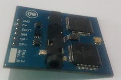
Figure 9-2 EMIC 2 TTS module
The header file remains the same. The main code is shown in Listing 9-4.
Listing 9-4 TTS Main Code
/** File: Main.c* Author: Armstrong Subero* PIC: 16F1717 w/Int OSC @ 16MHz, 5v* Program: 21_EUSART* Compiler: XC8 (v1.38, MPLAX X v3.40)* Program Version: 1.0*** Program Description: This Program Allows PIC16F1717 to communicate via the* EUSART module to a EMIC 2 TTS module.*** Hardware Description: A EMIC 2 TTS module is connected to the PIC16F1717 as* follows:** RB2-> SIN;* RB3-> SOUT;** The other pins on the EMIC2 TTS are connected as per* datasheet.** Created February 25th, 2017, 9:55 PM*//***************************************************************Includes and defines**************************************************************/#include "16F1717_Internal.h"#include "EUSART.h"/*************************************************************** Function: void initMain()*Returns: Nothing** Description: Contains initializations for main** Usage: initMain()*************************************************************/void initMain(){// Run at 16 MHzinternal_16();// Setup PINSTRISBbits.TRISB3 = 1;ANSELBbits.ANSB3 = 0;TRISBbits.TRISB2 = 0;ANSELBbits.ANSB2 = 0;/////////////////////// Setup EUSART////////////////////PPSLOCK = 0x55;PPSLOCK = 0xAA;PPSLOCKbits.PPSLOCKED = 0x00; // unlock PPSRB2PPSbits.RB2PPS = 0x14; //RB2->EUSART:TX;RXPPSbits.RXPPS = 0x0B; //RB3->EUSART:RX;PPSLOCK = 0x55;PPSLOCK = 0xAA;PPSLOCKbits.PPSLOCKED = 0x01; // lock PPS}/*************************************************************** Function: Main** Returns: Nothing** Description: Program entry point*************************************************************/void main(void) {initMain();char readEmic;// Initialize EUSART module with 9600 baudEUSART_Initialize(9600);// give the module time to stabilize__delay_ms(3000);// Send CR in case system is upEUSART_Write(13);while(1){// If TTS module is readyif (EUSART_Read() == 58){// Say somethingEUSART_Write(83);EUSART_Write_Text("Hello");EUSART_Write(13);__delay_ms(500);}}return;}
Using GPS (Global Positioning Systems)
Now we look at using GPS (Global Positioning System) . GPS is a system that utilizes satellites to determine the position to a GPS receiver, which receives a signal from these satellites. I simply cannot cover GPS in its entirety in this book, since it would just confuse everything. If you want to know how GPS works in detail, browse the Internet. Once you are satisfied, come back and learn how to use the module. A good feature of GPS is that is does not require an active Internet connection or cellular network in order to work.
In this example, we look at using the U-BLOX NEO-6M GPS module , as it is very easy to use and, at the time of this writing, is widely available and extremely low cost (see Figure 9-3).
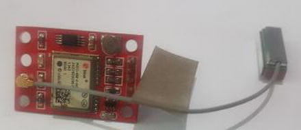
Figure 9-3 U-BLOX NEO-6M GPS module
NMEA Commands
In order to use the GPS module effectively, we must understand how the NMEA data transmitted by the GPS module works. NMEA stands for National Marine Electronics Association and that body produced a specification that allows the GPS receiver to give the time, position, and velocity data that the user can parse. The GPS receiver sends these commands as sentences in a particular format.
For the GPS receiver, these sentences all begin with a $ symbol followed by five letters. The first two letters are always GP followed by three other letters, which tell us what the sentence is about. For example, the sentence we are interested in is the GLL, which stands for Geographic Latitude and Longitude. The GLL type sentence has the following format:
$GPGLL,1123.01,N,1234.00,W,000111,A,*65The $GPGLL tells us the type of NMEA sentence it is. The fragment 1123.01,N tells us a position of latitude that’s 11 degrees and 23.01 minutes North. Similarly, 1234.00,W indicates a position of Longitude 12 degrees and 34.00 minutes West.
In order to extract the information about the position of the receiver, we need to create a buffer to store the information as it comes in. Then we need to eliminate any invalid data and use the C language strstr function, which is provided by XC8, to determine if the string we are looking for is present in the buffer.
I have a challenge for you. The code in Listing 9-5 has been written to display the coordinates to a HD44780 LCD (we cover this later in the chapter). Modify it to print to your serial LCD instead. (If you don’t want to do this, that is understandable and you may turn to Chapter 8, where the display is covered in full.)
Listing 9-5 GPS Main Code
/** File: Main.c* Author: Armstrong Subero* PIC: 16F1717 w/Int OSC @ 16MHz, 5v* Program: 21_EUSART* Compiler: XC8 (v1.38, MPLAX X v3.40)* Program Version: 1. 0*** Program Description: This Program Allows PIC16F1717 to communicate via the* EUSART module to a NEO-6M GPS module and display Latitude* and Longitude Coordinates on an LCD.** Hardware Description: A NEO-6M GPS module is connected to the PIC16F1717 as* follows:** PPS -> NC* RXD -> TX* TXD -> RX* GND -> GND* VCC -> VCC*** Created April 18th, 2017, 12:51 PM*//***************************************************************Includes and defines**************************************************************/#include "16F1717_Internal.h"#include "EUSART.h"#include "LCD.h"#include <string.h>// Variablesvolatile char c;volatile char d;char* data;static char uartBuffer[300];int i;char* terminator;char conversionString[8];double lat = 0.0;double lon = 0.0;double *longitude = &lon;double *latitude = ⪫// Function prototypevoid read_gps();/*************************************************************** Function: void initMain()** Returns: Nothing** Description: Contains initializations for main** Usage: initMain()**************************************************************/void initMain(){// Run at 16 MHzinternal_16();// Setup PINSTRISBbits.TRISB3 = 1;ANSELBbits.ANSB3 = 0;TRISBbits.TRISB2 = 0;ANSELBbits.ANSB2 = 0;TRISD = 0;ANSELD = 0;PORTD = 0;/////////////////////// Setup EUSART////////////////////PPSLOCK = 0x55;PPSLOCK = 0xAA;PPSLOCKbits.PPSLOCKED = 0x00; // unlock PPSRB2PPSbits.RB2PPS = 0x14; //RB2->EUSART:TX;RXPPSbits.RXPPS = 0x0B; //RB3->EUSART:RX;PPSLOCK = 0x55;PPSLOCK = 0xAA;PPSLOCKbits.PPSLOCKED = 0x01; // lock PPSINTCONbits.GIE = 1;INTCONbits.PEIE = 1;// set up UART 1 receive interruptPIE1bits.RCIE = 1;}/*************************************************************** Function: Main** Returns: Nothing** Description: Program entry point**************************************************************/void main(void) {initMain();Lcd_Init();Lcd_Clear();// Initialize EUSART module with 9600 baudEUSART_Initialize(9600);// give the module time to stabilize__delay_ms(100);while(1){Lcd_Set_Cursor(1,1);read_gps();// Write LatitudeLcd_Write_Float(*latitude);Lcd_Set_Cursor(2,1);// Write LongitudeLcd_Write_Float(*longitude);__delay_ms(2000);Lcd_Clear();}return;}/*************************************************************** Function: void read_gps()** Returns: Pointers to lat and lon** Description: Function to read the GPS module** Usage: read_gps()*************************************************************/void read_gps(){// Read characters from UART into bufferfor(i=0; i<sizeof(uartBuffer)-1; i++){d = EUSART_Read_Char(c);uartBuffer[i] = d;}// Last character is null terminatoruartBuffer[sizeof(uartBuffer)-1] = '�';// Look for needle in haystack to find string for GPGLLdata = strstr(uartBuffer, "$GPGLL");// if null exitif(data == NULL){return;}// Find terminatorterminator = strstr(data,",");// if null exitif(terminator == NULL){return;}// If the first byte of the latitude field is ',', there is no info// so exitif(data[7] == ','){return;}///////////////////////////////////// Search buffer data for Latitude// and Longitude values//////////////////////////////////data = terminator+1;terminator = strstr(data,",");if(terminator == NULL){return;}memset(conversionString,0,sizeof(conversionString));memcpy(conversionString, data, 2);*latitude = atof(conversionString);data += 2;*terminator = '�';*latitude += (atof(data)/60);data = terminator+1;terminator = strstr(data,",");if(terminator == NULL){return;}if(*data == 'S'){*latitude *= -1;}data = terminator+1;terminator = strstr(data,",");if(terminator == NULL){return;}memset(conversionString,0,sizeof(conversionString));memcpy(conversionString, data, 3);*longitude = atof(conversionString);data += 3;*terminator = '�';*longitude += (atof(data)/60);data = terminator+1;terminator = strstr(data,",");if(terminator == NULL){return;}if(*data == 'W'){*longitude *= -1;}}
Software USART
The PIC16F1717 only has one USART module that users can use in their applications. Now there may be situations where you need to use more than one USART module for your application. In this case, you may need to redesign your circuitry and utilize a chip that has more features. However, this is not as simple as it sounds, because you may already be familiar with the chip you are using for your application and may not want to bear the costs associated with using a larger chip. In such cases, it may be useful to use a software USART (also called a “bit-banged”) implementation.
The bit-banged USART we use in this example works reliably up to about 2400 baud rate. Higher bit rates may be unstable and may not function as intended.
GSM Module
We will look at an application of the bit-banged USART using a GSM module. We will use the SIM 800L module (see Figure 9-4), which is very popular at the time of writing and is very simple to use.

Figure 9-4 SIM800L module
AT Commands
In a previous section, we looked at data structured in NMEA format, which is the type of data commonly given by GSM modules. In this section, we look at using AT (attention) commands. AT commands are commonly used to control modems. Here are some commonly used AT commands for controlling the SIM 800L module:
AT: Check to see if the module is working correctly. If it is, it will return OK.
AT+CREG?: Get information about network registration. If the modules returns +CREG: 0,1, then everything is fine.
AT+IPR=9600: Change the baud rate. For example, changing the 9600 to 2400 in the example would set the baud rate to 2400.
The other AT commands are used for things like sending and receiving messages, calls, accessing the GPS features, among others. In this example, we will focus solely on sending text messages, so the commands for sending texts are shown in the code in Listing 9-6. Again another challenge—modify the code in Listing 9-6 to run with the serial LCD instead of the character LCD. If you don’t want to do this, you can instead turn to the section later in this chapter entitled “Character: The Hitachi HD44780 LCD” and use the code of the character LCD in that section.
Listing 9-6 GSM Main Code
/** File: Main.c* Author: Armstrong Subero* PIC: 16F1717 w/Int OSC @ 16MHz, 5v* Program: I08_GSMCompiler: XC8 (v1.38, MPLAX X v3.40)* Program Version: 1.0*** Program Description: This Program Allows PIC16F1717 to communicate with a* SIM800L GSM module and send an SMS message.*** Hardware Description: A SIM800L GSM module is connected as follows:*5v -> 5V*GND -> GND*VDD -> NC*SIM_TXD -> RX*SIM_RXD -> TX*GND -> GND*** Created April 18th, 2017, 1:11 PM*//***************************************************************Includes and defines**************************************************************/#include "16F1717_Internal.h"#include "LCD.h"// Setup for soft UART#define Baudrate 2400 //bps#define OneBitDelay (1000000/Baudrate)#define DataBitCount 8 // no parity, no flow control#define UART_RX LATEbits.LATE0// UART RX pin#define UART_TX LATEbits.LATE1 // UART TX pin#define UART_RX_DIR TRISE0// UART RX pin direction register#define UART_TX_DIR TRISE1 // UART TX pin direction register//Function Declarationsvoid InitSoftUART(void);unsigned char UART_Receive(void);void UART_Transmit(const char);void SUART_Write_Text(char *text);void SUART_Write_Char(char a);void SUART_Read_Text(char *Output, unsigned int length);/*************************************************************** Function: void initMain()** Returns: Nothing** Description: Contains initializations for main** Usage: initMain()**************************************************************/void initMain(){// Run at 16 MHzinternal_16();// Setup pinsTRISD = 0x00;ANSELD = 0x00;PORTD = 0x00;TRISE = 0;ANSELE = 0;}/*************************************************************** Function: Main** Returns: Nothing** Description: Program entry point**************************************************************/void main(void) {initMain();Lcd_Init();__delay_ms(1000);InitSoftUART(); // Initialize Soft UART__delay_ms(1000);while(1){// Send commands to moduleSUART_Write_Text("AT+CMGF=1 ");__delay_ms(1000);SUART_Write_Text("AT+CMGS="0009999" "); // replace number__delay_ms(1000);// Message to sendSUART_Write_Text("Test");__delay_ms(1000);UART_Transmit((char)26);__delay_ms(1000);// Notify user message sentLcd_Clear();Lcd_Set_Cursor(1,1);__delay_ms(100);// Write StringLcd_Write_String("Sent");__delay_ms(2000);}return;}/** Init SW UART*/void InitSoftUART(void) // Initialize UART pins to proper values{UART_TX = 1; // TX pin is high in idle stateUART_RX_DIR = 1; // InputUART_TX_DIR = 0; // Output}/** Receive via SW UART*/unsigned char UART_Receive(void){// Pin Configurations// GP1 is UART RX Pinunsigned char DataValue = 0;//wait for start bitwhile(UART_RX==1);__delay_us(OneBitDelay);__delay_us(OneBitDelay/2); // Take sample value in the mid of bit durationfor ( unsigned char i = 0; i < DataBitCount; i++ ){if ( UART_RX == 1 ) //if received bit is high{DataValue += (1<<i);}__delay_us(OneBitDelay);}// Check for stop bitif ( UART_RX == 1 ) //Stop bit should be high{__delay_us(OneBitDelay/2);return DataValue;}else //some error occurred !{__delay_us(OneBitDelay/2);return 0x000;}}/** Transmit via SW UART*/void UART_Transmit(const char DataValue){/* Basic LogicTX pin is usually high. A high to low bit is the starting bit anda low to high bit is the ending bit. No parity bit. No flow control.BitCount is the number of bits to transmit. Data is transmitted LSB first.*/// Send Start BitUART_TX = 0;__delay_us(OneBitDelay);for ( unsigned char i = 0; i < DataBitCount; i++ ){//Set Data pin according to the DataValueif(((DataValue>>i)&0x1) == 0x1 ) //if Bit is high{UART_TX = 1;}else //if Bit is low{UART_TX = 0;}__delay_us(OneBitDelay);}//Send Stop BitUART_TX = 1;__delay_us(OneBitDelay);}/** Write text via SW UART*/void SUART_Write_Text(char *text){int i;for(i=0;text[i]!='�';i++)UART_Transmit(text[i]);}/** Read text via SW UART*/void SUART_Read_Text(char *Output, unsigned int length){int i;for(int i=0;i<length;i++){Output[i] = UART_Receive();}}/** Write Char via SW UART*/void SUART_Write_Char(char a){UART_Transmit(a - 0x128);}
Using SPI (Serial Peripheral Interface)
Serial Peripheral Interface (SPI) is another type of serial communication protocol commonly used in embedded systems and present on the PIC® microcontroller . SPI is a very important protocol and is widely implemented on a variety of sensors. Unlike USART, where very few applications require a clock, in SPI a clock is present in all applications because SPI uses synchronous data transfer.
The device in the SPI communication that generates the clock is known as the master and the other is known as the slave. SPI always only has one master device, although there can be many slaves. SPI has several lines: Serial Clock (SCK), Master Out Slave In (MOSI) , Master In Slave Out (MISO) , and Slave Select (SS) . If there is only one slave device connected to the SPI bus, then this line may be left low as SPI is active low.
One of the major disadvantages of SPI is that it uses a lot of I/O lines. Although SCK, MOSI, and MISO remain the same regardless of the number of slave devices on the bus, an additional SS line must be used for each slave device that is connected to the bus. The advantage of SPI is that it can transfer millions of bytes of data per second and is useful when interacting with devices such as SD cards, which would require data transfer at very high speeds.
In learning to use the SPI peripheral available on the PIC® microcontroller, we will use an MCP4131 digital potentiometer with the PIC® microcontroller.
The code for the SPI was generated using the Microchip Code Configurator . There are a lot of tutorials on how to use the MCC, so I leave it up to you to learn on your own. I also leave you to figure out how to connect the SPI lines. Here’s a hint though—read the datasheet of the MCP4131. You need to make a few modifications to the names of the functions as per the header file. You must modify the names to match those as shown in the header file.
Listing 9-7 shows the modified header file from MCC for the SPI.
Listing 9-7 SPI Header
/** File: SPI.h* Author: Armstrong Subero* PIC: 16F1717 w/X OSC @ 16MHz, 5v* Program: Header file for SPI module* Compiler: XC8 (v1.38, MPLAX X v3.40)** Program Version 1.0** Program Description: This program header provides function prototypes for* SPI module on PIC16F1717**** Created on November 7th, 2016, 5:45 PM*//***************************************************************Includes and defines**************************************************************/#include "16F1717_Internal.h"#define DUMMY_DATA 0x0void SPI_Initialize(void);uint8_t SPI_Exchange8bit(uint8_t data);uint8_t SPI_Exchange8bitBuffer(uint8_t *dataIn, uint8_t bufLen, uint8_t *dataOut);bool SPI_IsBufferFull(void);bool SPI_HasWriteCollisionOccured(void);void SPI_ClearWriteCollisionStatus(void);
Digital Potentiometer
The digital potentiometer we use to demonstrate the use of the SPI bus is the MCP4131. The MCP4131 is a 7-bit device, giving a total of 129 different values, and is controlled via SPI. In this example, we send commands to the device and the device adjusts its resistance. The change in resistance is visible by connecting the POW pin of the device to an LED via a 1k resistor. The resistor will then vary in brightness.
Listing 9-8 provides the main code.
Listing 9-8 Main Code
/** File: Main.c* Author: Armstrong Subero* PIC: 16F1717 w/Int OSC @ 16MHz, 5v* Program: 22_SPI* Compiler: XC8 (v1.38, MPLAX X v3.40)* Program Version: 1.0*** Program Description: This Program Allows PIC16F1717 to communicate via the* SPI interface*** Hardware Description: A HD44780 LCD is connected via PORTD and a MCP4131* digital potentiometer is connected as follows:** Vss --> Vss* Vdd --> Vdd* SS --> RD1* SCK --> RC3* SDI --> RC5* POB --> GND* POW --> LED via 1k resistor* POA --> Vdd*** Created November 10th, 2016, 4:42 PM*//***************************************************************Includes and defines**************************************************************/#include "16F1717_Internal.h"#include "LCD.h"#include "SPI.h"void digiPot_write(int i);/*************************************************************** Function: void initMain()** Returns: Nothing** Description: Contains initializations for main** Usage: initMain()**************************************************************/void initMain(){// Run at 16 MHzinternal_16();// Set PIN D1 as outputTRISDbits.TRISD1 = 0;// Turn off LEDLATDbits.LATD1 = 0;// Setup PORTDTRISD = 0;ANSELD = 0;// Initialize LCDLcd_Init();__delay_ms(100);Lcd_Clear();// Setup PORTC for SPIANSELCbits.ANSC3 = 0;ANSELCbits.ANSC4 = 0;ANSELCbits.ANSC5 = 0;TRISCbits.TRISC3 = 0;TRISCbits.TRISC4 = 1;TRISCbits.TRISC5 = 0;PPSLOCK = 0x55;PPSLOCK = 0xAA;PPSLOCKbits.PPSLOCKED = 0x00; // unlock PPSSSPDATPPSbits.SSPDATPPS = 0x14; //RC4->MSSP:SDI;RC3PPSbits.RC3PPS =0x10; //RC3->MSSP:SCK;RC5PPSbits.RC5PPS =0x11; //RC5->MSSP:SDO;PPSLOCK = 0x55;PPSLOCK = 0xAA;PPSLOCKbits.PPSLOCKED = 0x01; // lock PPS// Initialize SPISPI_Initialize();}/*************************************************************** Function: Main** Returns: Nothing** Description: Program entry point**************************************************************/void main(void) {initMain();// Digipot variableint i;Lcd_Set_Cursor(1,1);__delay_ms(5);Lcd_Write_String("SPI Ready");__delay_ms(1000);Lcd_Clear();while(1){// Seven bit resolutionfor (i = 0; i <= 128; i++){// Write ValuedigiPot_write(i);// Write to LCDLcd_Set_Cursor(1,1);__delay_ms(5);Lcd_Write_Integer(i);__delay_ms(250);Lcd_Clear();}}return;}/*************************************************************** Function: Main** Returns: Nothing** Description: Writes a particular value to a MCP4131 digital potentiometer** Usage: digiPot_write(x);**************************************************************/void digiPot_write(int i){// Set SS LowLATDbits.LATD1 = 0;// Slave addressSPI_Exchange8bit(0x00);// DataSPI_Exchange8bit(i);// Set SS HighLATDbits.LATD1 = 1;}
Character Display
Although the focus of the next chapter is displays, we utilize a simple character LCD to demonstrate the I2C protocol.
Character: The Hitachi HD44780 LCD
The Hitachi HD44780 is known as the industry standard character LCD. The reason is simple—the HD44780 is very easy to use. The LCD is used to display characters to users. The most commonly used display type is the 2x16 variety, which displays up to 16 characters on two lines. The LCD is essential for any embedded toolbox and makes an excellent prototyping display.
The LCD commonly has 14 pins; however, LCDs that have a backlight have 16 pins. I recommend the version with the backlight. Download the datasheet for your particular display to determine which version display you have.
Let’s look at the code for using the HD44780 LCD.
First, Listing 9-9 shows the header file.
Listing 9-9 HD44780 Header File
/** File: LCD.h* Author: Armstrong Subero* PIC: 16F1717 w/X OSC @ 16MHz, 5v* Program: Header file to* Compiler: XC8 (v1.38, MPLAX X v3.40)* Program Version 1.1* *Added additional comments** Program Description: This program header provides routines for controlling* a STD HITACHI HD44780 and compatible LCDs** Hardware Description:** RS ---> RD2* R/W ---> GND* EN ---> RD3* D4 ---> RD4* D5 ---> RD5* D6 ---> RD6* D7 ---> RD7*** Created on November 7th, 2016, 11:56 PM*//***************************************************************Includes and defines**************************************************************/// STD XC8 include#include <xc.h>#define RS RD2 //Register Select (Character or Instruction)#define EN RD3 //LCD Clock Enable PIN, Falling Edge Triggered// 4 bit operation#define D4 RD4 //Bit 4#define D5 RD5 //Bit 5#define D6 RD6 //Bit 6#define D7 RD7 //Bit 7// function prototypesvoid Lcd_Port(char a);void Lcd_Cmd(char a);void Lcd_Clear();void Lcd_Set_Cursor(char a, char b);void Lcd_Init();void Lcd_Write_Char(char a);void Lcd_Write_String(const char *a);void Lcd_Shift_Right();void Lcd_Shift_Left();void Lcd_Write_Integer(int v);void Lcd_Write_Float(float f);
Next is the source file, provided in Listing 9-10.
Listing 9-10 HD44780 Source File
/** File: LCD.c* Author: Armstrong Subero* PIC: 16F1717 w/Int OSC @ 16MHz, 5v* Program: Library file to configure PIC16F1717* Compiler: XC8 (v1.38, MPLAX X v3.40)* Program Version: 1.1* *Added additional comments** Program Description: This Library allows you to interface HD44780 and* compatible LCDs** Created on November 7th, 2016, 11:55 AM*/#include "LCD.h"#include "16F1717_Internal.h"/*************************************************************** Function: void Lcd_Port (char a)** Returns: Nothing** Description: LCD Setup Routines**************************************************************/void Lcd_Port(char a){if(a & 1)D4 = 1;elseD4 = 0;if(a & 2)D5 = 1;elseD5 = 0;if(a & 4)D6 = 1;elseD6 = 0;if(a & 8)D7 = 1;elseD7 = 0;}/*************************************************************** Function: void Lcd_Cmd (char a)** Returns: Nothing** Description: Sets LCD command**************************************************************/void Lcd_Cmd(char a){RS = 0; // => RS = 0Lcd_Port(a);EN = 1; // => E = 1__delay_ms(1);EN = 0; // => E = 0}/*************************************************************** Function: void Lcd_Clear()** Returns: Nothing** Description: Clears the LCD**************************************************************/void Lcd_Clear(){Lcd_Cmd(0);Lcd_Cmd(1);}/*************************************************************** Function: void Lcd_Set_Cursor(char a, char b)** Returns: Nothing** Description: Sets the LCD cursor position**************************************************************/void Lcd_Set_Cursor(char a, char b){char temp,z,y;if(a == 1){temp = 0x80 + b - 1;z = temp>>4;y = temp & 0x0F;Lcd_Cmd(z);Lcd_Cmd(y);}else if(a == 2){temp = 0xC0 + b - 1;z = temp>>4;y = temp & 0x0F;Lcd_Cmd(z);Lcd_Cmd(y);}}/*************************************************************** Function: void Lcd_Init()** Returns: Nothing** Description: Initializes the LCD**************************************************************/void Lcd_Init(){Lcd_Port(0x00);__delay_ms(10);Lcd_Cmd(0x03);__delay_ms(3);Lcd_Cmd(0x03);__delay_ms(10);Lcd_Cmd(0x03);/////////////////////////////////////////////////////Lcd_Cmd(0x02);Lcd_Cmd(0x02);Lcd_Cmd(0x08);Lcd_Cmd(0x00);Lcd_Cmd(0x0C);Lcd_Cmd(0x00);Lcd_Cmd(0x06);}/*************************************************************** Function: void Lcd_Write_Char (char a)** Returns: Nothing** Description: Writes a character to the LCD**************************************************************/void Lcd_Write_Char(char a){char temp,y;temp = a&0x0F;y = a&0xF0;RS = 1; // => RS = 1Lcd_Port(y>>4); //Data transferEN = 1;__delay_us(20);EN = 0;Lcd_Port(temp);EN = 1;__delay_us(20);EN = 0;}/*************************************************************** Function: void Lcd_Write_String (const char *a)** Returns: Nothing** Description: Writes a string to the LCD**************************************************************/void Lcd_Write_String(const char *a){int i;for(i=0;a[i]!='�';i++)Lcd_Write_Char(a[i]);}/*************************************************************** Function: void Lcd_Shift_Right()** Returns: Nothing** Description: Shifts text on the LCD right**************************************************************/void Lcd_Shift_Right(){Lcd_Cmd(0x01);Lcd_Cmd(0x0C);}/*************************************************************** Function: void Lcd_Shift_Left()** Returns: Nothing** Description: Shifts text on the LCD left**************************************************************/void Lcd_Shift_Left(){Lcd_Cmd(0x01);Lcd_Cmd(0x08);}/*************************************************************** Function: void Lcd_Write_Integer(int v)** Returns: Nothing** Description: Converts a string to an integer**************************************************************/void Lcd_Write_Integer(int v){unsigned char buf[8];Lcd_Write_String(itoa(buf, v, 10));}/*************************************************************** Function: void Lcd_Write_Float(float f)** Returns: Nothing** Description: Converts a string to a float**************************************************************/void Lcd_Write_Float(float f){char* buf11;int status;buf11 = ftoa(f, &status);Lcd_Write_String(buf11);}
Finally, Listing 9-11 provides the source code that goes through all the routines.
Listing 9-11 HD44780 Main
/** File: Main.c* Author: Armstrong Subero* PIC: 16F1717 w/Int OSC @ 16MHz, 5v* Program: 15_HD44780_LCD* Compiler: XC8 (v1.38, MPLAX X v3.40)* Program Version: 1.0*** Program Description: This Program Allows PIC16F1717 to interface to* HD44780 and compatible LCDs** Hardware Description: An HD44780 compatible LCD is connected to PORTD of* the microcontroller as follows:** RS ---> RD2* R/W ---> GND* EN ---> RD3* D4---> RD4* D5---> RD5* D6---> RD6* D7---> RD7*** Created November 7th, 2016, 11:05 AM*//***************************************************************Includes and defines**************************************************************/#include "16F1717_Internal.h"#include "LCD.h"/*************************************************************** Function: void initMain()** Returns: Nothing** Description: Contains initializations for main** Usage: initMain()**************************************************************/void initMain(){// Run at 16 MHzinternal_16();TRISD = 0x00;ANSELD = 0x00;PORTD = 0x00;}/*************************************************************** Function: Main** Returns: Nothing** Description: Program entry point**************************************************************/void main(void) {initMain();Lcd_Init();int a;int c;float b;while(1){Lcd_Clear();Lcd_Set_Cursor(1,1);// Write StringLcd_Write_String("PIC16F1717");// Shift it leftfor(a=0;a<15;a++){__delay_ms(500);Lcd_Shift_Left();}// Shift it rightfor(a=0;a<15;a++){__delay_ms(500);Lcd_Shift_Right();}Lcd_Clear();Lcd_Set_Cursor(1,1);// Write Integerfor (c = 0; c < 100; c++){Lcd_Write_Integer(c);__delay_ms(300);Lcd_Clear();__delay_ms(15);}// Write Floatfor (b = 0.0; b <= 5; b+= 0.5){Lcd_Write_Float(b);__delay_ms(300);Lcd_Clear();__delay_ms(15);}__delay_ms(1000);}return;}
The Samsung KS0066U
The code in Listing 9-11 works on HD44780 and compatible LCDs, including the Samsung KS0066U and was tested on both displays.
Using the I2C (Inter-Integrated Circuit) Protocol
We now look at the final protocol presented in this chapter, the I2C (Inter-Integrated Circuit) protocol. There are a lot of tutorials that go in depth into the I2C protocol and thus I will not attempt to give a detailed explanation of it. There are some things that you must first know in order to use this protocol effectively.
The I2C protocol is widely used. When compared to SPI, I2C uses fewer (only two) lines but communication occurs at a slower rate and it is a very complex protocol. The example we look at is reading and writing an EEPROM. This is an important application because the PIC16F1717 does not have an onboard EEPROM.
I2C is unique when compared to the other protocols we have discussed so far in that only one line is used for data flow. On the I2C bus, the device known as the master is used to communicate with another device, known as the slave. The master can communicate with the slave because each device on the slave has its own address.
The lines used for the communication with the slave are the serial clock line (SCL) and serial data line (SDA) . In order for I2C to work, the lines must be connected to VCC using pull-up resistors. There are calculations that can be used to determine the value of these resistors by working out the capacity of the lines. In practice, however, I have found that either 4.7K or 1 K resistors do the job quite adequately.
These pull-up resistors are required because I2C devices pull the signal line low but cannot drive it high, and the pull-up resistors are there to restore the signal line to high.
The speed most I2C devices use to communicate is either 100kHz or 400kHz. The protocol transmits information via frames. There are two types of frames available—an address frame, which informs the bus which slave devices will receive the message, followed by data frames containing the actual 8-bit data. Every frame has a 9th bit, called the acknowledge (ACK) or not acknowledge (NACK) bit, which is used to indicate whether the slave device reads the transmission.
Every I2C communication from the master starts with the master pulling the SDA line low and leaving the SCL line high. This is known as the start condition. Similarly, there is a stop condition, where there is a low-to-high transition on SDA after a low-to-high transition on SCL with SCL being high.
EEPROM
The example we use for I2C is interfacing the microcontroller with an I2C based EEPROM device . The header file is shown in Listing 9-12.
Listing 9-12 I2C Header
/** File: I2C.h* Author: Armstrong Subero* PIC: 16F1717 w/X OSC @ 16MHz, 5v* Program: Header file to setup PIC16F1717 I2C* Compiler: XC8 (v1.35, MPLAX X v3.10)* Program Version 1.2* Separated file into Header and C source file* Used non-mcc code*** Program Description: This program header will allows set up of I2C** Created on September 12th, 2016, 7:00 PM*//***************************************************************Includes and defines**************************************************************/#include "16F1717_Internal.h"void I2C_Init(void);void Send_I2C_Data(unsigned int databyte);unsigned int Read_I2C_Data(void);void Send_I2C_ControlByte(unsigned int BlockAddress,unsigned int RW_bit);void Send_I2C_StartBit(void);void Send_I2C_StopBit(void);void Send_I2C_ACK(void);void Send_I2C_NAK(void);
The source file is shown in Listing 9-13.
Listing 9-13 I2C Source
/** File: I2C.c* Author: Armstrong Subero* PIC: 16F1717 w/Int OSC @ 16MHz, 5v* Program: Library file to configure PIC16F1717 I2C module* Compiler: XC8 (v1.38, MPLAX X v3.40)* Program Version: 1.1* *Added additional comments** Program Description: This Library allows you to control PIC16F1717 I2C** Created on November 12th, 2016, 7:05 AM*/#include "I2C.h"void I2C_Init(void){//********************************************************************// Setup MSSP as I2C Master mode, clock rate of 100Khz//********************************************************************SSPCONbits.SSPM=0x08;// I2C Master mode, clock = Fosc/(4 * (SSPADD+1))SSPCONbits.SSPEN=1; // enable MSSP port// ************************************************************************// The SSPADD register value is used to determine the clock rate for I2C// communication.// Equation for I2C clock rate: Fclock = Fosc/[(SSPADD +1)*4]//// For this example we want the the standard 100Khz I2C clock rate and our// internal Fosc is 16Mhz so we get: 100000 = 16000000/[(SSPADD+1)*4]// or solving for SSPADD = [(16000000/100000)-4]/4// and we get SSPADD = 39SSPADD = 39; // set Baud rate clock divider// ************************************************************************__delay_ms(10); // let everything settle.}//********************************************************************// Send one byte to SEE//********************************************************************void Send_I2C_Data(unsigned int databyte){PIR1bits.SSP1IF=0; // clear SSP interrupt bitSSPBUF = databyte; // send databytewhile(!PIR1bits.SSP1IF); // Wait for interrupt flag to go high indicatingtransmission is complete}//********************************************************************// Read one byte from SEE//********************************************************************unsigned int Read_I2C_Data(void){PIR1bits.SSP1IF=0; // clear SSP interrupt bitSSPCON2bits.RCEN=1;// set the receive enable bit to initiate a readof 8 bits from the serial EEPROMwhile(!PIR1bits.SSP1IF);// Wait for interrupt flag to go high indicatingtransmission is completereturn (SSPBUF); // Data from EEPROM is now in the SSPBUF so return that value}//********************************************************************// Send control byte to SEE (this includes 4 bits of device code, block select bits and the R/W bit)//**************************************************************************************// Notes:// 1) The device code for serial EEPROMs is defined as '1010' which we are usingin this example// 2) RW_bit can only be a one or zero// 3) Block address is only used for SEE devices larger than 4K, however on// some other devices these bits may become the hardware address bits that// allow you to put multiple devices of the same type on the same bus.// Read the datasheet on your particular serial EEPROM device to be sure.//********************************************************************void Send_I2C_ControlByte(unsigned int BlockAddress,unsigned int RW_bit){PIR1bits.SSP1IF=0; // clear SSP interrupt bit// Assemble the control byte from device code, block address bits and R/W bit// so it looks like this: CCCCBBBR// where 'CCCC' is the device control code// 'BBB' is the block address// and 'R' is the Read/Write bitSSPBUF = (((0b1010 << 4) | (BlockAddress <<1)) + RW_bit); // send the control bytewhile(!PIR1bits.SSP1IF);// Wait for interrupt flag to go high indicatingtransmission is complete}//********************************************************************// Send start bit to SEE//********************************************************************void Send_I2C_StartBit(void){PIR1bits.SSP1IF=0; // clear SSP interrupt bitSSPCON2bits.SEN=1; // send start bitwhile(!PIR1bits.SSP1IF); // Wait for the SSPIF bit to go back high beforewe load the data buffer}//********************************************************************// Send stop bit to SEE//********************************************************************void Send_I2C_StopBit(void){PIR1bits.SSP1IF=0; // clear SSP interrupt bitSSPCON2bits.PEN=1; // send stop bitwhile(!PIR1bits.SSP1IF);// Wait for interrupt flag to go high indicatingtransmission is complete}//********************************************************************// Send ACK bit to SEE//********************************************************************void Send_I2C_ACK(void){PIR1bits.SSP1IF=0; // clear SSP interrupt bitSSPCON2bits.ACKDT=0; // clear the Acknowledge Data Bit - this means weare sending an Acknowledge or 'ACK'SSPCON2bits.ACKEN=1; // set the ACK enable bit to initiate transmission of the ACK bit to the serial EEPROMwhile(!PIR1bits.SSP1IF); // Wait for interrupt flag to go high indicatingtransmission is complete}//********************************************************************// Send NAK bit to SEE//********************************************************************void Send_I2C_NAK(void){PIR1bits.SSP1IF=0; // clear SSP interrupt bitSSPCON2bits.ACKDT=1; // set the Acknowledge Data Bit- this means we are sending a No-Ack or 'NAK'SSPCON2bits.ACKEN=1; // set the ACK enable bit to initiate transmission of the ACK bit to the serial EEPROMwhile(!PIR1bits.SSP1IF); // Wait for interrupt flag to go high indicatingtransmission is complete}
Now for at the main code, shown in Listing 9-14.
Listing 9-14 Main File
/** File: Main.c* Author: Armstrong Subero* PIC: 16F1717 w/Int OSC @ 16MHz, 5v* Program: 24_I2C* Compiler: XC8 (v1.38, MPLAX X v3.40)* Program Version: 1.0*** Program Description: This Program Allows PIC16F1717 to communicate via the* I2C interface*** Hardware Description: A HD44780 LCD is connected via PORTD and a 24LC16B* EEPROM chip is connected to the I2C bus*** Created November 10th, 2016, 8:02 PM*//***************************************************************Includes and defines**************************************************************/#include "16F1717_Internal.h"#include "LCD.h"#include "I2C.h"/***************************************************************Includes and defines**************************************************************/int block_address = 0x00; // Set the EEPROM block address that we will write the data toint word_address = 0x00; // Set the EEPROM word address that we will write the data toint eeprom_data = 0x09; // This is the data we are going to writeint incoming_data;/*************************************************************** Function: void initmain(void)** Returns: Nothing** Description: Initializations for main**************************************************************/void initmain(void){internal_16();// Setup pins for I2CANSELCbits.ANSC4 = 0;ANSELCbits.ANSC5 = 0;TRISCbits.TRISC4 = 1;TRISCbits.TRISC5 = 1;PPSLOCK = 0x55;PPSLOCK = 0xAA;PPSLOCKbits.PPSLOCKED = 0x00; // unlock PPSRC4PPSbits.RC4PPS =0x0011; //RC4->MSSP:SDA;SSPDATPPSbits.SSPDATPPS =0x0014; //RC4->MSSP:SDA;SSPCLKPPSbits.SSPCLKPPS =0x0015; //RC5->MSSP:SCL;RC5PPSbits.RC5PPS =0x0010; //RC5->MSSP:SCL;PPSLOCK = 0x55;PPSLOCK = 0xAA;PPSLOCKbits.PPSLOCKED = 0x01; // lock PPS//Setup for LCDTRISD = 0;ANSELD = 0;//Setup LCDLcd_Init();__delay_ms(1000);Lcd_Clear();}/*************************************************************** Function: void main(void)** Returns: Nothing** Description: Program entry point**************************************************************/void main(void){initmain();I2C_Init();Lcd_Set_Cursor(1,1);Lcd_Write_String("I2C Ready");__delay_ms(1000);Lcd_Clear();while (1){///////////////////////////// Write EEPROM//////////////////////////Lcd_Set_Cursor(1,1);Lcd_Write_String("Write");__delay_ms(1000);Lcd_Clear();Send_I2C_StartBit(); // send start bitSend_I2C_ControlByte(block_address,0); // send control byte with R/W bitset lowSend_I2C_Data(word_address); // send word addressSend_I2C_Data(eeprom_data); // send data byteSend_I2C_StopBit();// send stop bit__delay_ms(200);/////////////////////////////// Read EEPROM////////////////////////////Lcd_Set_Cursor(1,1);Lcd_Write_String("Read");__delay_ms(1000);Lcd_Clear();Send_I2C_StartBit(); // send start bitSend_I2C_ControlByte(block_address,0); // send control byte with R/W bitset lowSend_I2C_Data(word_address); // send word addressSend_I2C_StartBit(); // send start bitSend_I2C_ControlByte(block_address,1); // send control byte with R/W bitset highincoming_data = Read_I2C_Data(); // read data coming back from the EEPROMSend_I2C_NAK(); // send NACK to tell EEPROM we don't want any more dataSend_I2C_StopBit();Lcd_Set_Cursor(1,1);Lcd_Write_Integer(incoming_data);__delay_ms(1000);Lcd_Clear();}}
Conclusion
In this chapter, we looked at USART, SPI, and I2C, which are the fundamental communication protocols of microcontroller-based systems. We also looked at GPS, GSM, LCDs, and a host of other things. Once you understand these communication protocols, you can easily interface your microcontroller to a host of sensors. At this point you can do quite a lot; however, keep reading because the next few chapters will take your skills to another level.