Let’s Get Started
In this chapter, we look at the process of connecting a PIC® microcontroller to an In-Circuit Serial Programmer, or ICSP. Some people also call them In-Circuit Debuggers, since they also have debugging capabilities. We look at the process of creating and running a new project in MPLAB X as well as creating source files. Beginners and first-time users of bare-bones microcontrollers should pay special attention to this chapter because, unlike the Arduino and other development boards, there is a need to connect the microcontroller to a programmer to load your program onto the chip. The process is not as “plug and play” as using a development board. So, let’s get started!
A Look at Programmers
As was explained in Chapter 1, there are different programmers you can use to program your PIC® microcontroller. The two most popular right now are the PICkit™ 3 and the MPLAB® ICD 3. (There is also an ICD 4; however, at the time of writing it does not support all of the PIC® chips and is not as popular as the aforementioned programmers.) Regardless of if you purchased an ICD 3 or a PICkit™ 3, the process of connecting the programmer to your microcontroller is the same.
We will not take an in-depth look at the mechanics of how these programmers work, because in this book, all we will look at is using them as programmers and will not explore their debugging capabilities. We will simply treat the programmers as “black boxes” that allow you to load your program onto the chip. Figure 5-1 shows a closeup of the PICkit™ 3 .

Figure 5-1 Closeup of PICkit™ 3
If you look in the foreground of Figure 5-1, you will see an arrow. This arrow is the position where you place the wire that is connected to the !MCLR pin of your microcontroller. Moving across to the left, the subsequent pins that will be connected are the Vdd pin, Vss pin, PGD (data) pin, and the PGC (clock) pin. There is also an LVP (low voltage programming) pin; however, we can safely ignore it for now.
If you are using the ICD 3, I strongly recommend that you buy an adapter that coverts the RJ-11 type connector on the programmer to an ICSP-type interface. As a beginner, this will make connecting the programmer to your various chips and development boards very easy, as you will be able to simply stick a wire into the connector and connect it to your chip. Figure 5-2 shows an example of how one of these RJ-11 to ICSP connectors looks. I also recommend you repeat these steps or connect the chip to the programmer with the programmer disconnected from your computer to avoid any mishaps.
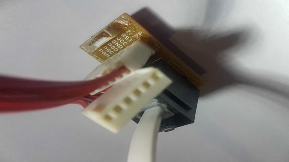
Figure 5-2 RJ-11 to ICSP adapter
Once you have set up your programmer, the next step is to connect the programmer to the physical chip. There are a lot of ways to do this. However, the simplest way is simply to connect a male to male jumper wire from the hole on the connector to the target device. Figure 5-3 shows how to connect the male jumper wire to the ISCP connector. After this process is done, you can connect the jumper wires to the PIC16F1717, as shown in Figure 5-4.
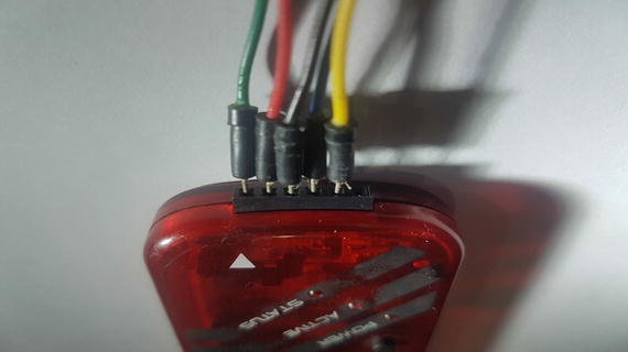
Figure 5-3 Connecting jumper wires to ICSP connector
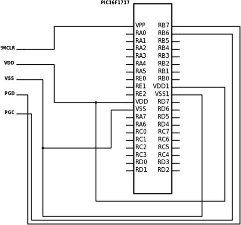
Figure 5-4 Connecting ICSP to PIC16F1717
A Look at Programming
After you have connected your programmer to your chip, you can plug in the USB cable from your programmer to your computer. If no magic smoke is released, and you have your programmer connected to the microcontroller, the next step is to write your program and download it to the microcontroller.
First, open MPLAB® X. You will be presented with the window shown in Figure 5-5.
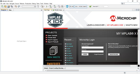
Figure 5-5 MPLAB® X home screen
Choose File ➤ New Project, as is indicated in the upper-left corner of the IDE shown in Figure 5-6.
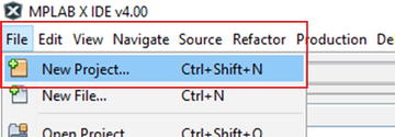
Figure 5-6 Creating a new project
Next, choose Microchip Embedded followed by Standalone Project, as shown in Figure 5-7.
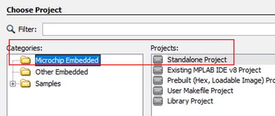
Figure 5-7 Selecting a standalone project
Next, select your device family followed by your device. In this case, it will be PIC16F1717. Type this into the Device box, as shown in Figure 5-8.
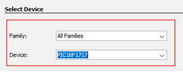
Figure 5-8 Choosing your device
Click Next and then Next again. Select the programmer you will be using from the Hardware Tools option. In this case, you select either the PICkit 3 or the ICD 3, as shown in Figure 5-9.
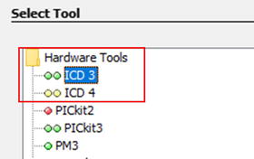
Figure 5-9 Selecting your hardware tool
Select your compiler. We will be using the XC8 compiler in this example, so ensure that this option is selected, as shown in Figure 5-10.
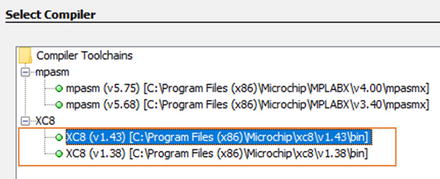
Figure 5-10 Choosing the XC8 compiler
Select a name for your project and choose a path. Then click the Finish button. This is depicted in Figure 5-11. Congratulations! You have created a new project!
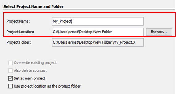
Figure 5-11 Naming your project and selecting a path
You should see your new project created, as shown in Figure 5-12.
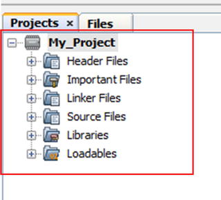
Figure 5-12 Newly created project
Now you are ready to write your program. In order to do this, you need to create header files and source files. Let’s look at how you create a source file.
Click the Source Files folder. Then right-click it and choose New. Create a new main.c file, as shown in Figure 5-13.
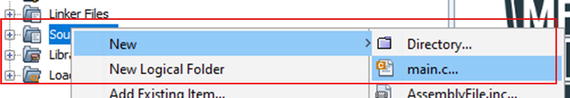
Figure 5-13 Creating a new main file
The process for creating a header file is the same. The difference is instead of clicking the Source Files folder, you click the Header Files folder and create a header file instead of a source file.
Your file will be created. We won’t run a program now.
Look the top of the IDE and you’ll see the two icons we’ll be using. The icon with the hammer and broom is the Clean and Build option and the green arrow is used to run the main project (see Figure 5-14). We use the Clean and Build button to verify that our program is free of errors. When you click the Run Main Project icon, the program will be loaded onto the microcontroller.
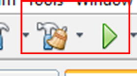
Figure 5-14 Clean and Build and Run Icons
If you try to run the current project and download it to your microcontroller, nothing will happen. This is because we haven’t given the microcontroller any instructions. In the next chapter, we look at writing a program to make the microcontroller do something.
Traps for Beginners
When you build your project, you expect that it will be loaded to the chip. There are some traps, however, that cause beginners to experience problems. The first trap is that the PICkit® 3 or ICD 3 does not provide power to your microcontroller by default and I recommend you keep it that way. Therefore, you need to power the target circuit from its own power source. The reason for this is when we start using inductive or high-current loads such as DC motors and servos, for example, we may draw more current than the programmer can provide.
The other trap you need to look out for is the length of your wires from the programmer to the chip. Keep these wires as short as possible, which will ensure that you do not experience any errors when trying to run your project.
The final trap you need to be careful about is having a noisy power supply. I recommend you use a dedicated power supply, as it will have the least amount of noise. Even with a good power supply, I recommend you still use some smoothing capacitors on the supply rails. Countless avoidable problems can be traced to having a noisy power supply.
Remember that programming a chip is a complex process and a lot of things happen in the background. Therefore, anything can go wrong. It is very important that you pay attention to the output window. It will save you many hours of frustration.
Remember also to triple check your connections. Sometimes you’ll accidently connect things the way they ought not be connected. PIC® microcontrollers are resilient and easy-to-use devices, but there are some rules you must pay attention to.
Additional Information
Should you need more information about how the actual programming of the PIC microcontroller is carried out, I recommend you look at app note DS30277. Microchip also provides a lot of information on their web site about using PIC microcontrollers in general at www.microchip.com . There are lots of additional resources on the manufacturer’s web site.
Conclusion
This chapter looked at the process of connecting our microcontroller to our programmer. We also looked at the processes of creating a new project source file as well as how you would go about building and running a project.